CN112739957B - Air purifying device - Google Patents
Air purifying device Download PDFInfo
- Publication number
- CN112739957B CN112739957B CN201880097662.1A CN201880097662A CN112739957B CN 112739957 B CN112739957 B CN 112739957B CN 201880097662 A CN201880097662 A CN 201880097662A CN 112739957 B CN112739957 B CN 112739957B
- Authority
- CN
- China
- Prior art keywords
- air
- main body
- filter unit
- body case
- intake passage
- Prior art date
- Legal status (The legal status is an assumption and is not a legal conclusion. Google has not performed a legal analysis and makes no representation as to the accuracy of the status listed.)
- Active
Links
Images


Classifications
-
- F—MECHANICAL ENGINEERING; LIGHTING; HEATING; WEAPONS; BLASTING
- F24—HEATING; RANGES; VENTILATING
- F24F—AIR-CONDITIONING; AIR-HUMIDIFICATION; VENTILATION; USE OF AIR CURRENTS FOR SCREENING
- F24F8/00—Treatment, e.g. purification, of air supplied to human living or working spaces otherwise than by heating, cooling, humidifying or drying
- F24F8/10—Treatment, e.g. purification, of air supplied to human living or working spaces otherwise than by heating, cooling, humidifying or drying by separation, e.g. by filtering
-
- F—MECHANICAL ENGINEERING; LIGHTING; HEATING; WEAPONS; BLASTING
- F24—HEATING; RANGES; VENTILATING
- F24F—AIR-CONDITIONING; AIR-HUMIDIFICATION; VENTILATION; USE OF AIR CURRENTS FOR SCREENING
- F24F11/00—Control or safety arrangements
- F24F11/50—Control or safety arrangements characterised by user interfaces or communication
- F24F11/52—Indication arrangements, e.g. displays
-
- F—MECHANICAL ENGINEERING; LIGHTING; HEATING; WEAPONS; BLASTING
- F24—HEATING; RANGES; VENTILATING
- F24F—AIR-CONDITIONING; AIR-HUMIDIFICATION; VENTILATION; USE OF AIR CURRENTS FOR SCREENING
- F24F11/00—Control or safety arrangements
- F24F11/88—Electrical aspects, e.g. circuits
-
- F—MECHANICAL ENGINEERING; LIGHTING; HEATING; WEAPONS; BLASTING
- F24—HEATING; RANGES; VENTILATING
- F24F—AIR-CONDITIONING; AIR-HUMIDIFICATION; VENTILATION; USE OF AIR CURRENTS FOR SCREENING
- F24F13/00—Details common to, or for air-conditioning, air-humidification, ventilation or use of air currents for screening
- F24F13/20—Casings or covers
-
- F—MECHANICAL ENGINEERING; LIGHTING; HEATING; WEAPONS; BLASTING
- F24—HEATING; RANGES; VENTILATING
- F24F—AIR-CONDITIONING; AIR-HUMIDIFICATION; VENTILATION; USE OF AIR CURRENTS FOR SCREENING
- F24F7/00—Ventilation
- F24F7/003—Ventilation in combination with air cleaning
-
- F—MECHANICAL ENGINEERING; LIGHTING; HEATING; WEAPONS; BLASTING
- F24—HEATING; RANGES; VENTILATING
- F24F—AIR-CONDITIONING; AIR-HUMIDIFICATION; VENTILATION; USE OF AIR CURRENTS FOR SCREENING
- F24F8/00—Treatment, e.g. purification, of air supplied to human living or working spaces otherwise than by heating, cooling, humidifying or drying
- F24F8/80—Self-contained air purifiers
-
- F—MECHANICAL ENGINEERING; LIGHTING; HEATING; WEAPONS; BLASTING
- F24—HEATING; RANGES; VENTILATING
- F24F—AIR-CONDITIONING; AIR-HUMIDIFICATION; VENTILATION; USE OF AIR CURRENTS FOR SCREENING
- F24F13/00—Details common to, or for air-conditioning, air-humidification, ventilation or use of air currents for screening
- F24F13/20—Casings or covers
- F24F2013/205—Mounting a ventilator fan therein
-
- F—MECHANICAL ENGINEERING; LIGHTING; HEATING; WEAPONS; BLASTING
- F24—HEATING; RANGES; VENTILATING
- F24F—AIR-CONDITIONING; AIR-HUMIDIFICATION; VENTILATION; USE OF AIR CURRENTS FOR SCREENING
- F24F2221/00—Details or features not otherwise provided for
- F24F2221/02—Details or features not otherwise provided for combined with lighting fixtures
-
- Y—GENERAL TAGGING OF NEW TECHNOLOGICAL DEVELOPMENTS; GENERAL TAGGING OF CROSS-SECTIONAL TECHNOLOGIES SPANNING OVER SEVERAL SECTIONS OF THE IPC; TECHNICAL SUBJECTS COVERED BY FORMER USPC CROSS-REFERENCE ART COLLECTIONS [XRACs] AND DIGESTS
- Y02—TECHNOLOGIES OR APPLICATIONS FOR MITIGATION OR ADAPTATION AGAINST CLIMATE CHANGE
- Y02B—CLIMATE CHANGE MITIGATION TECHNOLOGIES RELATED TO BUILDINGS, e.g. HOUSING, HOUSE APPLIANCES OR RELATED END-USER APPLICATIONS
- Y02B30/00—Energy efficient heating, ventilation or air conditioning [HVAC]
- Y02B30/70—Efficient control or regulation technologies, e.g. for control of refrigerant flow, motor or heating
Abstract
The invention improves the designability of the air purification device. The air purification device (10) takes in external air from the lower part, filters the air by the filter unit (40), and then discharges the air to the outside. Comprises the following steps: an intake passage (16) formed as a tunnel-shaped passage that penetrates the lower portion of the main body case (12); an air passage (42) which is connected to the air intake passage (16) from above and extends upward inside the main body case; and an illumination unit (34) which is provided at the upper rear portion of the intake passage (16) and illuminates light downward and forward from substantially the entire width of the lateral width of the intake passage.
Description
Technical Field
The present invention relates to an air cleaning apparatus for cleaning air by a filter unit.
Background
Various air cleaning devices have been sold in the past. These air cleaning devices are mainly intended to remove house dust, mold, pollen, bacteria, viruses, and the like in indoor air, and air cleaning devices using ultraviolet rays, a photocatalyst, and negative ions are also known, but a filter is mainly used to remove fine particles and the like.
Patent document 1 proposes that air that has not passed through the filter is also taken in and circulated by using two fans, and that a function as a circulator is also added to purify air in a wider range.
Documents of the prior art
Patent literature
Patent document 1: japanese patent laid-open publication No. 2013-217580
Disclosure of Invention
Problems to be solved by the invention
Here, the air cleaner is often placed indoors at a place where human eyes reach, and it is preferable that the air cleaner not only has excellent functions but also has a beautiful design. In addition, it is considered preferable that the state of dust in the air can be recognized.
Means for solving the problems
The present invention provides an air cleaning device which takes in external air from the lower part, filters the air by a filter unit and then discharges the air to the outside, the air cleaning device comprises: an intake passage formed as a tunnel-shaped passage (1258812412493; an air passage connected to the intake passage from above and extending upward inside the main body case; and an illumination unit which is provided at an upper portion of the intake passage at the rear thereof and illuminates light downward and forward from substantially the entire width of the intake passage.
The cross-section of the air passage may be quadrilateral.
The main body case may be a quadrangular prism, and the air intake passage may be a passage penetrating from the front surface to the back surface.
When the illumination unit is turned on, the supply of power to the illumination unit may be controlled to gradually turn on the illumination unit, thereby simulating the movement of light from the illumination unit from the rear to the front.
The blowing mode may be at least three types of blowing intensities, and the lighting intensity of the lighting unit may be controlled to be larger as the blowing intensity is larger.
Effects of the invention
According to the present invention, light can be supplied to the through intake passage by the illumination unit, and the design of the air cleaning device can be improved.
Drawings
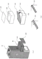
Fig. 1 is a diagram showing an external appearance of an air cleaner according to an embodiment.
Fig. 2 is a view showing an internal structure of the air cleaning apparatus, wherein (a) is a plan view, (b) is a front view cut by a plane passing through a chain line (front-back direction) in (a), and (c) and (d) are isometric views.
Fig. 3 is a view showing an internal structure of the air cleaner, (a) is a plan view, (b) is a front view cut by a plane passing through a chain line (left-right direction) in (a), and (c) and (d) are isometric views.
Fig. 4 is a diagram showing the flow of air (air flow path) in the air cleaning device.
Fig. 5 is a view showing the structure of the illumination unit 34, (a) is a view seen from the front, (b) is a view seen from the rear and upper side of the intake passage 16 (showing a part of the illumination unit), and (c) is a view showing a cross section cut along a front-rear direction plane.
Fig. 6 is a diagram showing the lighting state of the lighting unit 34, where (a) shows the off state, (b) shows the state immediately after lighting, (c) shows the state in which a little time has elapsed after lighting, and (d) shows the state of full lighting (maximum illuminance).
Fig. 7 is a diagram showing a state in which the filter unit 40 is taken out, (a) shows a state in which the filter unit is being taken out, and (b) shows a state in which the filter unit is disassembled.
Fig. 8 is a diagram showing the structure of the insertion portion of the filter unit 40 and the support unit 120, where (a) is an internal state in which the filter unit 40 is inserted into the main body case 12, (b) is an internal state in which the filter unit 40 is removed from the main body case 12, (c) is a state in which the filter unit 40 is removed from the main body case 12, and (d) is a diagram showing the internal structure of the support unit.
Fig. 9 is a diagram showing a configuration example of the rotary blade 54.
Fig. 10 is a view showing the structure of the stationary blade 60, where (a) is a perspective view and (b) is a plan view.
Fig. 11 is a diagram showing streamlines (analysis results) of the air flow, where (a) shows a case where the stationary blade 60 is present, and (b) shows a case where the stationary blade 60 is absent.
Detailed Description
Hereinafter, embodiments of the present invention will be described with reference to the drawings. The present invention is not limited to the embodiments described herein.
'integral structure'
Fig. 1 shows an external appearance of an air cleaner according to an embodiment. The air cleaner 10 has a quadrangular prism shape as a whole. The main body case 12 covers peripheral portions of the side surfaces and the upper surface.
A front surface air intake opening 14 is formed in a lower portion of the front surface of the main body case 12. As will be described later, the front surface intake opening 14 is an opening of the front surface of the intake passage 16 having a tunnel-like cross section of a rectangular shape, the intake passage 16 penetrates to the rear surface, and a rear surface intake opening 30 (see fig. 2) of the rear surface is formed on the rear surface side (rear side).
A circular fan shroud (1250112449\\ 1254089) is removably provided on an upper surface of the body case 12, which constitutes the exhaust opening 20.
Further, a concave portion 22 for a user to grip and lift up the hand is formed in a longitudinal middle portion of the left and right side surfaces of the main body case 12 (only the right side surface is shown in fig. 1). A plurality of operation switch buttons 24 are provided at a corner portion on the front surface side of the upper surface of the main body case 12.
Fig. 2 and 3 are diagrams showing an internal configuration of the air cleaner, fig. 2 (a) is a plan view, (b) is a front view of the case of being cut by a surface passing a chain line (front-rear direction) in (a), (c) and (d) are perspective views of the case of being cut by a surface passing a chain line (front-rear direction) in (a), fig. 3 (a) is a plan view, (b) is a front view of the case of being cut by a surface passing a chain line (left-right direction) in (a), and (c) and (d) are perspective views of the case of being cut by a surface passing a chain line (left-right direction) in (a).
Thus, a rear intake opening 30 is formed on the rear surface side of the intake passage 16. The intake passage 16 is widely opened at the upper side, and a vertical air passage 32 is formed therein. Further, an illumination portion 34 is provided on the upper side of the rear surface side of the intake passage 16. The illumination unit 34 is provided with a plurality of LEDs over substantially the full width in the left-right width direction, and irradiates light obliquely forward to supply light to substantially the entire intake passage 16.
A filter unit 40 is disposed above the air passage 32. The filter unit 40 is provided so as to block the air passage 32, and the air from the air passage 32 passes through the filter unit 40, and is filtered and purified. The filter unit 40 has a 2-stage structure of a pleated dust collecting filter (filter for removing dust, dirt, etc.) formed by folding a long thin filter material and a deodorizing filter (filter for adsorbing an odor generating substance) formed by attaching activated carbon, a catalyst substance, etc. to a fiber material, and is detachable. That is, a portion of the body case 12 on the back side corresponding to the filter unit 40 is detachable (fig. 2 shows a state where the portion is detached), and the filter unit 40 can be pulled out on the back side. Further, it is also appropriate to provide a prefilter for simple filtering at the lowermost portion of the filter unit 40.
An air passage 42 is formed above (downstream side of) the filter unit 40, and the air passage 42 is tapered upward and has a smaller cross-sectional area. That is, the tubular wall 44 forming the air passage 42 gradually gets closer to the inside of the main body case 12. A fan shroud 48 is provided at the narrowed portion (small diameter portion). The fan shroud 48 is formed by connecting concentric plates by radial plates, and protects the fan shroud from human hands or the like from entering from below by partitioning a space.
Further, a circuit board 46 is disposed in a space between the wall 44 and the main body case 12. A circuit for controlling the supply of power to the fan motor 50 in response to the operation of the switch button 24 and a circuit for controlling the illumination of the illumination unit 34 are mounted on the circuit board 46. A dust sensor and a gas sensor are mounted on the circuit board 46, and the fan motor 50 and the illumination unit 34 are also controlled based on the detection results of these sensors. In the present embodiment, an illuminance sensor for detecting the brightness of the surroundings is also provided, and when the surroundings are dark, the rotation speed of the fan motor can be reduced to reduce the noise. The illuminance sensor may be disposed on an upper surface of the main body case 12.
The air passage 42 above the fan shroud 48 is extended in a tapered shape, and a fan motor 50 is provided at an upper portion thereof. The fan motor 50 is fixed to a central portion of the air passage 42 by a support member 52. Further, the support member 52 has openings that do not substantially obstruct the flow of air.
The fan motor 50 rotates the rotary blades 54 to generate an air flow. The fan motor 50 and the rotary blades 54 constitute a blower fan 56. The rotary blades 54 are of an axial flow type, and the blower fan 56 is an axial flow fan. The blower fan 56 sucks air from the air passage 42 and supplies the air upward. That is, the air from the intake passage 16 passes through the filter unit 40 and is blown upward.
A stationary blade 60 for rectifying the airflow from the blower fan 56 is disposed above the rotary blade 54. The stationary blade 60 is composed of a dome body bulging upward at the center and a plurality of blades extending radially from the dome body, and concentrates the air flow sent by the rotary blade 54 in the center direction.
A fan shroud 18 is disposed on the upper surface of the main body casing 12 above the stationary blades 60. The fan shroud 18 is circular in overall shape, and is provided with a plurality of radial rods to prevent entry of hands, various objects, and the like.
In this air cleaner 10, the fan motor 50 is driven to rotate the rotary blades 54, thereby forming an upward air flow. An air flow path is formed in the main body case 12 through the air intake passage 16, the air passage 32, the filter unit 40, the rotary blades 54, the stationary blades 60, and the fan shroud 18, and as shown in fig. 4, the indoor air sucked from the front surface air intake opening 14 and the rear surface air intake opening 30 is sent upward through the air flow path.
"Structure of illumination part 34"
Fig. 5 shows a structure of the illumination unit 34. Fig. 5 (a) is a view seen from the front, (b) is a view seen from the rear and upward in the intake passage 16 (showing a part of the illumination portion), and (c) is a view showing a cross section cut along a front-rear direction plane.
The illumination section 34 has a semi-cylindrical transparent cover 100 fixed to the rear surface portion of the body casing 12 at the rear upper portion of the intake passage 16. A plate-shaped LED substrate 102 is disposed in the inner space of the transparent cover 100 so as to extend in the left-right direction. The surface of the LED substrate 102 faces diagonally downward and forward. A plurality of LED elements 104 are arranged on the LED substrate 102 at laterally spaced intervals. Therefore, by causing the plurality of LED elements 104 to emit light, light can be emitted downward and forward, and light can be supplied to substantially the entire intake passage 16. Power is supplied from the circuit board 46 to the LED element 104.
"illuminance control in illumination unit 34"
The lighting unit 34 can adjust the light emission intensity of the LED element 104 by a signal from the circuit board 46. That is, the illumination brightness for the intake passage 16 can be changed.
Fig. 6 (a) to (d) show the illumination states of the illumination unit 34. The light-off state (a), the light-on state (b), the state immediately after the light-on (c), the state in which a little time has elapsed after the light-on (d), and the fully-on (maximum illuminance) state (d) are shown. Therefore, as shown in (a) to (d), by gradually increasing the illumination intensity, it is possible to simulate a state in which the illumination moves from the rear to the front. Thus, since the movement can be simulated without using a mechanical moving means, unnecessary sound is not generated, and problems such as abrasion do not occur. Further, the design is excellent.
Further, by gradually changing the illumination intensity to change the illumination range region of the predetermined or more, the dust in the air in the intake passage 16 can be easily recognized at a predetermined luminance during the change. Therefore, the user easily recognizes the state of dust.
For example, by turning on the power switch, the illumination of the illumination unit 34 is started from immediately after the air cleaner 10 is started, and the change in the illumination state from the off state to the maximum illumination intensity may be repeated 1 time or a predetermined number of times.
Then, the illumination is continued during the operation at an illuminance corresponding to the blowing intensity (fan intensity) of the blower fan set by the user's operation.
As will be described later, there are a plurality of stages (at least 3 stages) of fan intensity, and the illumination intensity of the illumination portion 34 increases as the fan intensity increases according to the fan intensity.
When the blowing mode is changed, the light emission intensity is temporarily weakened, and then the light emission intensity corresponding to the mode is set. This makes it possible to reliably recognize that an operation has been performed.
When the predetermined time has elapsed while the lighting device is in the predetermined lighting state, the illuminance may be changed as described above. Further, when the operation is continued for a predetermined time, the lamp may be turned off, or when the predetermined time has elapsed after the turning-off time, the lamp may be turned on at a predetermined intensity or the illuminance may be changed as described above.
Here, as will be described later, the air blowing mode includes an "automatic mode" in which the fan intensity is automatically changed, in addition to the fan intensity settings such as "strong", "medium", and "weak" by manual operation. In this automatic mode, when the fan intensity is changed, the illumination intensity may be temporarily reduced and then set to an illumination intensity corresponding to the set fan intensity. This makes it easy for the user to recognize that the fan intensity is automatically changed. The user may expect the changes.
"Structure of Filter Unit 40"
The filter unit 40 is externally removable as described above. Fig. 7 shows a state in which the filter unit 40 is taken out, (a) shows a state in which the filter unit is being taken out, and (b) shows an operation of taking out the deodorizing filter from the filter unit 40.
Thus, the dust collecting filter 110 and the deodorizing filter 114 are housed in the filter frame (manufactured by the aforementioned patent publication No. \1252312479112. As shown in fig. 7 (a), the rear surface portion of the main body case 12 corresponding to the filter unit 40 is a detachable lid 118, and by detaching the lid 118, the filter unit 40 can be integrally put in and taken out of the main body case 12. Therefore, the filter unit 40 can be removed, cleaned, and replaced or replaced as necessary. Here, as shown in fig. 7 (b), the deodorizing filter 114 is supported at its periphery by a step on the inner wall of the filter frame 112. A stopper 116 is rotatably attached to an upper end portion of a near-side wall (hand side wall) of the filter frame 112. By rotating the stopper 116 from the proximal side to the inner side, the front end portion thereof catches the upper surface of the proximal side of the deodorizing filter 114 to hold the deodorizing filter 114. On the other hand, by turning the stopper 116 from the back side to the near side, the tip of the stopper 116 is disengaged from the deodorizing filter 114, and the deodorizing filter 114 can be taken out from the filter frame 112.
"Structure of insertion part of Filter Unit 40"
Fig. 8 (a) to (d) show the structure of the insertion portion of the filter unit 40. The internal state (a) is the state in which the filter unit 40 is inserted into the main body case 12, (b) is the internal state in which the filter unit 40 is removed from the main body case 12, (c) is a perspective view of the state in which the filter unit 40 is removed from the main body case 12, and (d) is a view showing the internal structure of the support unit.
The space inside the main body case 12 into which the filter unit 40 is inserted is slightly larger than the filter unit 40. Then, the frame-shaped upper end surface of the filter unit 40 (the upper end of the filter frame 112) is pushed upward, whereby the air-tight connection (sealing) with the upper air passage 42 is enabled.
Therefore, the support units 120 are disposed at both lower left and right end portions of the space in the main body case 12 into which the filter unit 40 is inserted. The support unit 120 includes a pair of spring units 122 including a vertical spring therein, a pair of support bodies 124 for suppressing vertical movement to a predetermined value or less, and a top panel 126 having an upper surface.
The upper panel 126 has inclined portions on the near side and the far side, and a flat portion in the middle. Therefore, when the filter unit 40 is inserted from the back side, the lower end of the front portion of the filter unit 40 first comes into contact with the inclined portion of the upper panel 126, and then the filter unit 40 is pressed in, whereby the support unit 120 is moved downward against the spring force. Therefore, when the filter unit 40 is pushed forward in this state and the insertion of the filter unit 40 is completed, the filter unit 40 is released and the filter unit 40 is pushed upward by the spring force of the support unit 120.
In addition, since the support unit 120 can be moved downward when the filter unit 40 is removed, it can be easily removed. Further, the lower side of the filter unit 40 is an intake port for external air connected to the intake passage 16, and is not required to be sealed.
"Structure of rotating blade 54 and stationary blade 60"
Fig. 9 shows an example of the configuration of the rotary blade 54. In this way, a plurality of blades 132 are attached to the periphery of the central cylindrical core 130. The vanes 132 extend obliquely downward from the upper end at the inner end, and the outer end is positioned with a slight gap with respect to the inner circumference of the cylindrical passage. The core 130 is fixed at its center to the rotation shaft of the fan motor 50. The rotating blades 54 are of an axial type, and are rotated by the rotating blades 54 to generate an axial air flow.
Fig. 10 shows the structure of the stationary blade 60, in which (a) is a perspective view and (b) is a plan view. A dome portion 142 having a shape bulging upward is disposed at the center of the cylindrical outer wall 140, and a plurality of plate members 144 extending in the radial direction are disposed between the outer wall 140 and the dome portion 142. The surface of each plate member 144 is slightly inclined at a predetermined angle (in the same direction) with respect to the axial direction. Thus, the air flow including the swirling flow generated by the rotation of the rotary vane 54 is rectified by the stationary blade 60, and is sent upward as a linear flow.
Fig. 11 shows streamlines of the air flow in the case where the stationary blade 60 is present and the case where the stationary blade 60 is absent (analysis result). The air flow in the circumferential direction is suppressed by the stationary blades 60, and thereby, a straight upward air flow is generated.
By rectifying the rotational flow in this way, the amount of air blown by the air cleaner is increased, and more effective indoor air purification is performed.
Automatic mode "
The air cleaning device 10 of the embodiment has an automatic mode. In this automatic mode, the rotation speed of the rotary blade 54 and the like are controlled based on the detection results of various sensors and the like.
The strength of the blower fan can be increased when the amount of surrounding dust detected by the dust sensor is large, or the strength of the blower fan can be increased when the amount of a predetermined gas detected by the gas sensor (the strength corresponding to an odor) is large.
When the illuminance sensor detects that the surroundings are dark, it is determined that the fan is asleep and the fan intensity is restricted (for example, the fan intensity is prohibited from increasing) to reduce the operating sound.
Further, in the manual mode, the user can select the fan intensity by a button operation.
Here, when the detection values of the dust sensor and the gas sensor are obtained separately, the fan intensity obtained from the detection values of both sensors may be higher.
In addition, the deodorizing filter 114 may not remove all kinds of odors reacted by the gas sensor. Therefore, when the fan intensity is set high because the detection value obtained from the gas sensor is high, it is preferable to sequentially decrease the fan intensity when a certain time has elapsed. For example, when the fan intensity level corresponding to the detection value of the gas sensor is high, the fan intensity level can be sequentially reduced to a medium level, a low level, an idle level, and the like at predetermined time intervals.
The fan strength can be set to three levels of strong, medium, and weak, for example.
When the air in the room is to be purified in a short time, it is preferable that the spray cleaning mode is selected by the user's operation and the fan is operated at a high speed for a predetermined time.
Description of the symbols
10 air cleaning device, 12 main body case, 14 front surface air inlet opening, 16 air inlet passage, 18, 48 fan shield, 20 air outlet opening, 22 concave part, 24 on-off button, 30 back surface air inlet opening, 32 air passage, 34 lighting part, 40 filter unit, 42 air passage, 44 wall, 46 circuit substrate, 50 fan motor, 52 support, 54 rotating blade, 56 blower fan, 60 stationary blade, 100 transparent cover, 102 substrate, 104LED element, 110 dust collection filter, 112 filter frame, 114 deodorization filter, 116 stop, 118 cover, 120 support unit, 122 spring unit, 124 support, 126 upper panel, 130 core material, 132 blade, 140 outer wall, 142 dome part, 144 plate material.
Claims (14)
1. An air purification device, comprising:
a main body case;
an intake passage formed at a lower side of the main body case; and
a vertical air passage extending upward from an opening formed in an upper side of the intake passage in the main body case and opening to an exhaust opening in an upper surface of the main body case,
wherein:
a filter unit provided so as to block the air passage and filtering the air flowing therethrough; and
a blower fan disposed downstream of the filter unit and blowing air upward,
wherein the air intake passage is a visible tunnel-shaped passage that passes through from a front surface air intake opening provided at a front surface lower portion of the main body case to a rear surface air intake opening provided at a rear surface lower portion of the main body case,
the air taken in from the front surface air inlet opening and the back surface air inlet opening is filtered by the filter unit and then discharged from the air outlet opening to the outside,
an illumination portion for illuminating the intake passage is provided so that a user can easily recognize a dust state, and the illumination portion is provided at a rear upper portion of the intake passage.
2. The air purification apparatus according to claim 1,
a stator blade for rectifying air from the blower fan is disposed downstream of the blower fan.
3. The air purification apparatus according to claim 2,
the stationary blade concentrates the air flow from the blower fan in the center direction to form an air flow having a small width of the air flow cross section.
4. The air purification apparatus according to claim 1,
a circuit board for controlling the driving of the blower fan is accommodated in a space between: a wall surrounding an air passage between the filter unit and the blower fan, and the main body case.
5. The air purification apparatus according to claim 4,
the wall is tubular, and the main body shell is quadrangular prism-shaped.
6. The air purifying apparatus according to claim 1,
the illumination unit irradiates light downward and forward from substantially the entire width of the lateral width of the intake passage.
7. The air purification apparatus according to claim 6,
the light intensity of the illumination unit is gradually increased, whereby the pseudo light moves forward from the rear of the intake passage.
8. The air purification apparatus according to claim 1,
the cross section of the intake passage is quadrilateral.
9. The air purification apparatus according to claim 1,
the blowing mode of the blowing fan is at least three according to blowing intensity,
when the blowing mode is changed, the illumination unit temporarily reduces the light emission intensity and then sets the light emission intensity corresponding to the changed blowing mode.
10. The air purification apparatus according to claim 1,
the illumination unit is controlled so that the illumination intensity is increased as the blowing intensity is increased.
11. The air purifying apparatus according to claim 9,
when the changed blowing mode continues for a predetermined time, the illumination unit is turned off.
12. The air purifying apparatus according to claim 1,
the filter unit is insertably detachable with respect to the main body case,
a support unit for supporting the filter unit is provided on the main body case,
the support unit includes a spring unit for biasing the filter unit upward when the filter unit is inserted.
13. The air purifying device of claim 12,
a dust collecting filter and a deodorizing filter can be accommodated in the filter unit,
the strength of the blowing fan is controlled by the detection values of the dust sensor and the gas sensor.
14. The air purification apparatus according to claim 13,
when a certain time has elapsed with the detection value of the gas sensor high, the strength of the blower fan is reduced.
Applications Claiming Priority (1)
| Application Number | Priority Date | Filing Date | Title |
|---|---|---|---|
| PCT/JP2018/038735 WO2020079790A1 (en) | 2018-10-17 | 2018-10-17 | Air cleaning device |
Publications (2)
| Publication Number | Publication Date |
|---|---|
| CN112739957A CN112739957A (en) | 2021-04-30 |
| CN112739957B true CN112739957B (en) | 2023-02-28 |
Family
ID=70284651
Family Applications (1)
| Application Number | Title | Priority Date | Filing Date |
|---|---|---|---|
| CN201880097662.1A Active CN112739957B (en) | 2018-10-17 | 2018-10-17 | Air purifying device |
Country Status (5)
| Country | Link |
|---|---|
| JP (1) | JP7109109B2 (en) |
| KR (1) | KR102546487B1 (en) |
| CN (1) | CN112739957B (en) |
| TW (1) | TWI821418B (en) |
| WO (1) | WO2020079790A1 (en) |
Families Citing this family (1)
| Publication number | Priority date | Publication date | Assignee | Title |
|---|---|---|---|---|
| KR102338380B1 (en) | 2021-06-02 | 2021-12-13 | 에이치케이시스템 | Wet type multifunctional air filter |
Citations (20)
| Publication number | Priority date | Publication date | Assignee | Title |
|---|---|---|---|---|
| JPH02184314A (en) * | 1989-01-06 | 1990-07-18 | Sanyo Electric Co Ltd | Air cleaner |
| JP2008185279A (en) * | 2007-01-30 | 2008-08-14 | Sanyo Electric Co Ltd | Floor type air conditioner |
| CN101843917A (en) * | 2010-05-07 | 2010-09-29 | 徐杏忠 | Air cleaning unit with illumination device |
| JP2011158143A (en) * | 2010-01-29 | 2011-08-18 | Sanyo Electric Co Ltd | Method of controlling air cleaner and humidifier |
| CN202002229U (en) * | 2011-04-08 | 2011-10-05 | 徐杏忠 | Air cleaning unit convenient for processing dust |
| CN102597526A (en) * | 2009-10-28 | 2012-07-18 | 国誉株式会社 | Blower |
| CN203810579U (en) * | 2014-05-09 | 2014-09-03 | 常州市伟泰电子科技有限公司 | Module-replacement type air purifier |
| CN204176789U (en) * | 2014-09-30 | 2015-02-25 | 宁波巨凰暖通设备有限公司 | A kind of air cleaner |
| CN104458520A (en) * | 2014-11-06 | 2015-03-25 | 江舫 | Dust sensor and space dust detection method |
| CN106989464A (en) * | 2017-05-27 | 2017-07-28 | 梅立功 | A kind of integrating device with air-cleaning function and illumination functions |
| CN107202412A (en) * | 2017-07-25 | 2017-09-26 | 天津贝罗尼生物科技有限公司 | A kind of air purifier intelligent-induction system |
| CN206695252U (en) * | 2016-04-18 | 2017-12-01 | 首尔伟傲世有限公司 | Air purifier |
| CN206709255U (en) * | 2017-05-10 | 2017-12-05 | 湖州梦源环保科技有限公司 | A kind of environment-friendly highly efficient air purifier |
| CN206803347U (en) * | 2017-03-08 | 2017-12-26 | 李世恩 | A kind of negative oxygen ion air cleaning machine |
| KR20180024125A (en) * | 2016-08-28 | 2018-03-08 | 포미주식회사 | System for ventilating windowless barn |
| CN207263579U (en) * | 2017-08-01 | 2018-04-20 | 武汉四方光电科技有限公司 | A kind of dust concentration detection device |
| WO2018097560A1 (en) * | 2016-11-22 | 2018-05-31 | 서울바이오시스주식회사 | Air purifier |
| KR20180088560A (en) * | 2017-01-26 | 2018-08-06 | (주)카인클린 | Stationary Air Purifier in a Car |
| CN207881006U (en) * | 2018-02-09 | 2018-09-18 | 江南大学 | A kind of household is convenient for clean air purifier |
| CN207962981U (en) * | 2017-12-28 | 2018-10-12 | 无锡晓鸣知识产权服务有限公司 | A kind of air purifier with efficient deodorizing function |
Family Cites Families (26)
| Publication number | Priority date | Publication date | Assignee | Title |
|---|---|---|---|---|
| JPS6220412U (en) * | 1985-07-23 | 1987-02-06 | ||
| JP2000088324A (en) * | 1998-09-09 | 2000-03-31 | Sanyo Electric Co Ltd | Air cleaner |
| JP4439625B2 (en) * | 1999-08-31 | 2010-03-24 | パナソニック株式会社 | air purifier |
| JP2005143524A (en) * | 2003-11-11 | 2005-06-09 | Daiken Kagaku Kogyo Kk | Air cleaner |
| JP4861746B2 (en) * | 2006-05-25 | 2012-01-25 | エアサイクルハウジング株式会社 | Ventilation equipment |
| JP2008123923A (en) * | 2006-11-15 | 2008-05-29 | Ee T Giken Kk | Lighting system |
| KR20100056797A (en) * | 2008-11-20 | 2010-05-28 | 삼성전자주식회사 | Air conditioner |
| JP2011078937A (en) * | 2009-10-09 | 2011-04-21 | Fu-Chi Wu | Air cleaner |
| JP5515863B2 (en) * | 2010-03-04 | 2014-06-11 | パナソニック株式会社 | Air purifier and air purifier with humidification function |
| KR101299505B1 (en) * | 2011-09-19 | 2013-08-29 | 엘지전자 주식회사 | An air cleaner |
| JP5864344B2 (en) * | 2012-04-09 | 2016-02-17 | バルミューダ株式会社 | Air purifier |
| JP2014087715A (en) * | 2012-10-29 | 2014-05-15 | Nec Corp | Dust-proof unit, filter and method for exchange of filter |
| KR102149198B1 (en) * | 2013-11-25 | 2020-08-28 | 엘지전자 주식회사 | Air conditioner |
| JP5855301B1 (en) * | 2014-05-27 | 2016-02-09 | 株式会社アクシー | Filter device and filter pressing unit used therefor |
| KR102220214B1 (en) * | 2014-07-25 | 2021-02-25 | 엘지전자 주식회사 | Air purifier |
| JP2016034602A (en) * | 2014-08-01 | 2016-03-17 | バルミューダ株式会社 | Air cleaner |
| CN104132437B (en) * | 2014-08-14 | 2017-08-29 | 上海嘉成轨道交通安全保障系统股份公司 | The air inlet mechanism and control method of air cleaning system |
| JP2016044586A (en) * | 2014-08-22 | 2016-04-04 | 日立アプライアンス株式会社 | Outdoor unit of air conditioner |
| KR101651488B1 (en) * | 2014-11-05 | 2016-08-26 | 엘지전자 주식회사 | Air Purifier |
| JP6730272B2 (en) * | 2014-11-06 | 2020-07-29 | ソウル バイオシス カンパニー リミテッドSeoul Viosys Co.,Ltd. | Small air purifier using UV LED and photocatalytic filter |
| KR101510610B1 (en) * | 2015-01-20 | 2015-04-14 | 유제빈 | Air cleaner with a vase shape |
| CN205227572U (en) * | 2015-11-26 | 2016-05-11 | 宁波博来净化科技有限公司 | Indoor air purifier |
| JP2017109158A (en) * | 2015-12-15 | 2017-06-22 | シャープ株式会社 | Air cleaner |
| JP6768448B2 (en) * | 2016-10-14 | 2020-10-14 | シャープ株式会社 | Humidifier and air purifier |
| CN108119823A (en) * | 2017-12-22 | 2018-06-05 | 广东科立盈光电技术有限公司 | A kind of LED light with light purifying gas flow circulatory function |
| WO2020079789A1 (en) * | 2018-10-17 | 2020-04-23 | バルミューダ株式会社 | Air cleaning apparatus |
-
2018
- 2018-10-17 JP JP2020551662A patent/JP7109109B2/en active Active
- 2018-10-17 CN CN201880097662.1A patent/CN112739957B/en active Active
- 2018-10-17 KR KR1020217008051A patent/KR102546487B1/en active IP Right Grant
- 2018-10-17 WO PCT/JP2018/038735 patent/WO2020079790A1/en active Application Filing
-
2019
- 2019-09-27 TW TW108134984A patent/TWI821418B/en active
Patent Citations (20)
| Publication number | Priority date | Publication date | Assignee | Title |
|---|---|---|---|---|
| JPH02184314A (en) * | 1989-01-06 | 1990-07-18 | Sanyo Electric Co Ltd | Air cleaner |
| JP2008185279A (en) * | 2007-01-30 | 2008-08-14 | Sanyo Electric Co Ltd | Floor type air conditioner |
| CN102597526A (en) * | 2009-10-28 | 2012-07-18 | 国誉株式会社 | Blower |
| JP2011158143A (en) * | 2010-01-29 | 2011-08-18 | Sanyo Electric Co Ltd | Method of controlling air cleaner and humidifier |
| CN101843917A (en) * | 2010-05-07 | 2010-09-29 | 徐杏忠 | Air cleaning unit with illumination device |
| CN202002229U (en) * | 2011-04-08 | 2011-10-05 | 徐杏忠 | Air cleaning unit convenient for processing dust |
| CN203810579U (en) * | 2014-05-09 | 2014-09-03 | 常州市伟泰电子科技有限公司 | Module-replacement type air purifier |
| CN204176789U (en) * | 2014-09-30 | 2015-02-25 | 宁波巨凰暖通设备有限公司 | A kind of air cleaner |
| CN104458520A (en) * | 2014-11-06 | 2015-03-25 | 江舫 | Dust sensor and space dust detection method |
| CN206695252U (en) * | 2016-04-18 | 2017-12-01 | 首尔伟傲世有限公司 | Air purifier |
| KR20180024125A (en) * | 2016-08-28 | 2018-03-08 | 포미주식회사 | System for ventilating windowless barn |
| WO2018097560A1 (en) * | 2016-11-22 | 2018-05-31 | 서울바이오시스주식회사 | Air purifier |
| KR20180088560A (en) * | 2017-01-26 | 2018-08-06 | (주)카인클린 | Stationary Air Purifier in a Car |
| CN206803347U (en) * | 2017-03-08 | 2017-12-26 | 李世恩 | A kind of negative oxygen ion air cleaning machine |
| CN206709255U (en) * | 2017-05-10 | 2017-12-05 | 湖州梦源环保科技有限公司 | A kind of environment-friendly highly efficient air purifier |
| CN106989464A (en) * | 2017-05-27 | 2017-07-28 | 梅立功 | A kind of integrating device with air-cleaning function and illumination functions |
| CN107202412A (en) * | 2017-07-25 | 2017-09-26 | 天津贝罗尼生物科技有限公司 | A kind of air purifier intelligent-induction system |
| CN207263579U (en) * | 2017-08-01 | 2018-04-20 | 武汉四方光电科技有限公司 | A kind of dust concentration detection device |
| CN207962981U (en) * | 2017-12-28 | 2018-10-12 | 无锡晓鸣知识产权服务有限公司 | A kind of air purifier with efficient deodorizing function |
| CN207881006U (en) * | 2018-02-09 | 2018-09-18 | 江南大学 | A kind of household is convenient for clean air purifier |
Also Published As
| Publication number | Publication date |
|---|---|
| WO2020079790A1 (en) | 2020-04-23 |
| TWI821418B (en) | 2023-11-11 |
| JP7109109B2 (en) | 2022-07-29 |
| JPWO2020079790A1 (en) | 2021-09-02 |
| CN112739957A (en) | 2021-04-30 |
| KR102546487B1 (en) | 2023-06-22 |
| TW202018235A (en) | 2020-05-16 |
| KR20210044857A (en) | 2021-04-23 |
Similar Documents
| Publication | Publication Date | Title |
|---|---|---|
| KR102275299B1 (en) | Air washer | |
| KR100508312B1 (en) | Air cleaner | |
| US7632340B2 (en) | Air purifier for removing particles or contaminants from air | |
| KR101729021B1 (en) | Air Purifier | |
| CN105987446B (en) | Compact air purifier including UV light emitting diode and photocatalytic filter | |
| JP5192745B2 (en) | Display device and air conditioner | |
| CN109073251A (en) | Air purifier | |
| KR101663514B1 (en) | Air Purifier | |
| CN105987445B (en) | Compact air purifier including UV light emitting diode and photocatalytic filter | |
| CN112739957B (en) | Air purifying device | |
| WO2006137650A1 (en) | Indoor floating dust collecting apparatus using convection flow | |
| CN109780608A (en) | Range hood | |
| JPH10241455A (en) | Lighting system equipped with air cleaning function | |
| JP2004069157A (en) | Air cleaner | |
| TWI816891B (en) | Air purifier | |
| KR100564648B1 (en) | Circulating Range Hood equipped with Air Cleaner | |
| CN107143931B (en) | Air purifier | |
| JP2013070791A (en) | Air purifier | |
| KR100550121B1 (en) | Air cleaner | |
| KR101760294B1 (en) | Air Purifier | |
| JP2004125374A (en) | Air cleaner | |
| JP2008249307A (en) | Air cleaner | |
| KR100804296B1 (en) | Air cleaner having additional filter | |
| KR200260536Y1 (en) | Range hood | |
| KR20160053647A (en) | Air Purifier |
Legal Events
| Date | Code | Title | Description |
|---|---|---|---|
| PB01 | Publication | ||
| PB01 | Publication | ||
| SE01 | Entry into force of request for substantive examination | ||
| SE01 | Entry into force of request for substantive examination | ||
| GR01 | Patent grant | ||
| GR01 | Patent grant |