CN112720961A - PTFE high strength membrane apparatus for producing - Google Patents
PTFE high strength membrane apparatus for producing Download PDFInfo
- Publication number
- CN112720961A CN112720961A CN202110112092.2A CN202110112092A CN112720961A CN 112720961 A CN112720961 A CN 112720961A CN 202110112092 A CN202110112092 A CN 202110112092A CN 112720961 A CN112720961 A CN 112720961A
- Authority
- CN
- China
- Prior art keywords
- fixed
- adjusting
- guide
- oven
- supporting
- Prior art date
- Legal status (The legal status is an assumption and is not a legal conclusion. Google has not performed a legal analysis and makes no representation as to the accuracy of the status listed.)
- Granted
Links
Images


Classifications
-
- B—PERFORMING OPERATIONS; TRANSPORTING
- B29—WORKING OF PLASTICS; WORKING OF SUBSTANCES IN A PLASTIC STATE IN GENERAL
- B29C—SHAPING OR JOINING OF PLASTICS; SHAPING OF MATERIAL IN A PLASTIC STATE, NOT OTHERWISE PROVIDED FOR; AFTER-TREATMENT OF THE SHAPED PRODUCTS, e.g. REPAIRING
- B29C55/00—Shaping by stretching, e.g. drawing through a die; Apparatus therefor
- B29C55/02—Shaping by stretching, e.g. drawing through a die; Apparatus therefor of plates or sheets
-
- B—PERFORMING OPERATIONS; TRANSPORTING
- B29—WORKING OF PLASTICS; WORKING OF SUBSTANCES IN A PLASTIC STATE IN GENERAL
- B29C—SHAPING OR JOINING OF PLASTICS; SHAPING OF MATERIAL IN A PLASTIC STATE, NOT OTHERWISE PROVIDED FOR; AFTER-TREATMENT OF THE SHAPED PRODUCTS, e.g. REPAIRING
- B29C35/00—Heating, cooling or curing, e.g. crosslinking or vulcanising; Apparatus therefor
- B29C35/16—Cooling
-
- B—PERFORMING OPERATIONS; TRANSPORTING
- B65—CONVEYING; PACKING; STORING; HANDLING THIN OR FILAMENTARY MATERIAL
- B65H—HANDLING THIN OR FILAMENTARY MATERIAL, e.g. SHEETS, WEBS, CABLES
- B65H19/00—Changing the web roll
- B65H19/10—Changing the web roll in unwinding mechanisms or in connection with unwinding operations
- B65H19/12—Lifting, transporting, or inserting the web roll; Removing empty core
- B65H19/126—Lifting, transporting, or inserting the web roll; Removing empty core with both-ends supporting arrangements
Abstract
The invention relates to a PTFE high-strength film production device, which comprises a spreader and an uncoiling mechanism arranged at the feed end of the spreader, wherein the spreader comprises a rack and an oven, a pair of conveying chains for clamping two sides of a film to convey the film through the oven are arranged on the rack, the return end of each conveying chain is positioned outside the oven, a plurality of sections of cooling boxes are arranged outside the return end of each conveying chain, each section of cooling box is connected with a suction pipe, the suction pipe is connected with a cooling fan, a secondary cooling box is arranged outside the process end of the conveying chain at the front end of the oven, blowing pipes for blowing air to the conveying chains are arranged on the front side and the rear side of the secondary cooling box, and the blowing pipes are connected with the. According to the invention, the return end of the conveying chain on the expander is arranged outside the oven and is matched with the cooling box arranged at the return end of the conveying chain, so that the temperature of the conveying chain can be reduced through air suction cooling, and the expanding quality of products is improved.
Description
Technical Field
The invention belongs to the technical field of film production, and particularly relates to a PTFE high-strength film production device.
Background
The PTFE high strength membrane is prepared by a biaxial stretching method and used in the new energy industry, the PTFE high strength membrane plays a role in supporting and ion passing, the longitudinal tensile strength is greater than or equal to 220Mpa, the transverse tensile strength is greater than 20Mpa, the porosity is about 85%, a short PTFE high strength membrane needs to be stretched in an oven by an expander in the production process of the PTFE high strength membrane, so that the PTFE high strength membrane is prepared, but the existing expander enters and exits the oven by chains clamping two ends of the PTFE high strength membrane, so that the time that the chains are in the oven is long, and after the time is long, the temperature of the chains can be greatly higher than the temperature required by stretching the PTFE high strength membrane, so that the product production is unqualified. And the PTFE high-strength film uncoiling mechanism at the front end of the expander only coils the PTFE high-strength film on the uncoiling shaft, so that the time is wasted when the film coil is replaced.
Disclosure of Invention
The invention aims to provide a PTFE high-strength film production device, which solves the problems that the existing tenter chain is too high in temperature, so that products are unqualified, and a film roll is not easy to replace by an uncoiling mechanism.
The invention relates to a PTFE high-strength film production device, which comprises a spreader and an uncoiling mechanism arranged at the feed end of the spreader, wherein the spreader comprises a rack and an oven, a pair of conveying chains for clamping two sides of a film to convey the film through the oven are arranged on the rack, the return end of each conveying chain is positioned at the outer side of the oven, a multi-section cooling box is arranged at the outer side of the return end of each conveying chain, wraps the return end of each conveying chain to enable the conveying chains to pass through the cooling boxes, each cooling box is connected with a suction pipe, the suction pipe is connected with a cooling fan, a secondary cooling box is arranged at the outer side of the process end of the conveying chain at the front end of the oven, blowing pipes for blowing air to the conveying chains are arranged at the front side and the back side of the secondary cooling boxes, the blowing pipes are connected with blowing fans, the blowing fans pump air outside a plant area to blow out air, and the, the top of secondary cooling case also is equipped with the suction tube of connecting the cooling fan, unwinding mechanism includes two backup pads that are parallel to each other, the lower part outer end of a side support plate rotates and installs the carousel, evenly rotate on the carousel and install and be no less than two back shafts, the rear end fixedly connected with switching motor of carousel, switching motor is step motor, can control rotatory angle, the backup pad lower part outer end of front side rotates and installs the drive shaft coaxial with the back shaft of below, drive shaft front end fixedly connected with opens a book the motor, it is adjustable speed motor to open a book the motor, can control the speed of broken book, be equipped with connecting device between drive shaft and the back shaft of below.
The connecting device comprises a polygonal connecting block, a sliding groove for accommodating the connecting block to slide axially is formed in the inner end face of the driving shaft, a compression spring is fixed to the bottom of the sliding groove, the outer end of the compression spring is fixed to the connecting block, a strip-shaped groove is formed in the side wall of the inner end of the driving shaft, an opening for communicating the sliding groove is formed in the bottom of the strip-shaped groove, a driving lever fixed to the connecting block is arranged in the opening, a polygonal blind hole matched with the connecting block is formed in the inner end face of each supporting shaft, and. Can drive the connecting block shrink through undulant driving lever for in the connecting block breaks away from the blind hole, remove the connection of back shaft and drive shaft, thereby provide convenience for the rotatory change of lap of rotary disk.
A second guide roller and a supporting roller are rotatably mounted on the supporting plate between the driving shaft and the first guide roller, the supporting roller is located between the first guide roller and the second guide roller, and the heights of the driving shaft, the second guide roller, the supporting roller and the first guide roller are sequentially increased in the vertical direction, so that a film roll is convenient to replace and is not interfered.
The outer wall of the supporting roll is uniformly provided with a plurality of flattening rods made of elastic materials, pressing plates are arranged at two ends of each flattening rod, annular flanges for pressing the flattening rods on the supporting roll are arranged on the outer sides of the inner ends of the pressing plates, positioning blind holes for positioning the flattening rods are arranged on the outer sides of the inner end faces of the pressing plates, a C-shaped limiting snap ring is arranged on the outer side of each pressing plate, an annular limiting clamping groove for clamping the limiting snap ring is formed in the circumference of the outer end of the supporting roll, and the supporting plate is lower than the inner end in a stepped. The film in the periphery can be flattened by the flattening rod, and the film wrinkles are prevented from influencing the expanding effect when entering the conveying chain.
The frame comprises an upper group of cross beams and a lower group of cross beams, a plurality of longitudinal beams are fixed between the upper group of cross beams and the lower group of cross beams, two horizontal support frame plates are arranged at the upper part of the left end of the frame, a conveying chain wheel for driving a conveying chain is rotatably arranged at the left end of each support frame plate, the conveying chain wheel is connected with a conveying motor, the conveying motor is an adjustable speed motor, a rolling support roller capable of rolling at the top of each longitudinal beam and a guide sleeve capable of sliding and guiding on each longitudinal beam are fixed at the bottoms of two ends of each support frame plate, the guide sleeve and the support frame plates are fixed through a connecting rod I, an adjusting rack I is fixed on each longitudinal beam, the adjusting rack I is meshed with an adjusting gear I, the adjusting gear I is fixedly connected with an adjusting motor I, the adjusting motor I is fixedly connected with the support frame plates, thereby adapt to the membrane book of different width, the left side of oven is equipped with two and is the expansion supporting beam of outer splayed form, and the both ends bottom of expansion supporting beam is equipped with adjusting nut one, and adjusting nut one is connected with adjusting screw one, and the other end of adjusting screw one passes the oven and is connected with adjusting motor two.
The right-hand member of oven is equipped with the support crossbearer of two parallels, the cover has gliding support sliding sleeve around can on the longeron of right-hand member, support sliding sleeve top is rotated and is installed the conveying sprocket of drive conveyor chain other end, conveying sprocket fixedly connected with conveyor motor, it is fixed with the support sliding sleeve to support the crossbearer right-hand member, the right side of support sliding sleeve is fixed with adjusting motor three, three fixedly connected with adjusting gear of adjusting motor is two, adjusting gear meshes the regulation rack two that has vertical setting, two right-hand members of adjusting rack are fixed with the installation longeron, the installation longeron is fixed on the crossbeam, it is fixed with adjusting nut two to support crossbearer left end bottom, adjusting nut two is connected with adjusting screw two, the other end of adjusting. The width of the unfolding support beam and the width of the support cross frame can be respectively adjusted through adjusting the motors from two to four, so that the film stretcher is suitable for films with different widths and films with different stretched widths. One side of the oven is provided with a maintenance door. And position sensors are arranged below the second adjusting nut and the first adjusting nut and are connected with a controller, and the controller is connected with a display screen, a second adjusting motor and a third adjusting motor.
The outer end of the conveying chain is uniformly provided with a plurality of clamping devices for clamping the edge part of the film, each clamping device comprises a fixed clamping plate fixed at the lower part of the outer side of the conveying chain, a movable clamping plate is arranged at the outer side of the upper part of the fixed clamping plate, a guide rod is fixed at the top part of the movable clamping plate, a guide sleeve is sleeved at the outer side of the guide rod, a spring sleeved on the guide rod is arranged in the lower part of the guide sleeve, a second connecting rod is hinged at the top part of the guide rod, a third connecting rod is hinged at the top part of the second connecting rod, a rotating sleeve is fixedly connected at the top part of the third connecting rod, the rotating sleeve is rotatably arranged on a pin shaft which is fixed on a support plate, an opening driving rod is fixed at the upper part of the rotating sleeve, a driving disc for stirring the opening, the inner side of the guide sleeve is fixed with a fourth connecting rod, the upper ends of the fourth connecting rod are fixed on the support plate, the inner sides of the support frame plate, the unfolding support beam and the support cross frame are respectively provided with a guide groove, a rolling bearing capable of rolling in the guide grooves is arranged in the guide grooves, and the rolling bearing is rotatably arranged at the bottom of the outer side of the conveying chain wheel. Can make to open the actuating lever through the driving-disc and rotate around the round pin axle when passing through to drive connecting rod two and connecting rod three actions, make the guide arm overcome the elasticity upward movement of spring, make move splint and open with fixed splint and press from both sides the mouth, make things convenient for film limit portion to get into, move the splint in addition and can clip the limit portion of film, need not clip too much, prevent to lead to the fact film limit portion too thick because of the too much of limit portion clamp. The lower end of the guide rod is connected with the movable clamping plate through threads. The top of the movable clamping plate is provided with a groove for supporting the spring. The support plate is arranged to be detachable, so that the spring working in a long-term high-temperature environment can be conveniently detached and replaced.
The inner sides of the outer ends of the cooling boxes at the left end and the right end are provided with guide chain wheels, the guide chain wheels are rotatably installed on the cross beam, the outer ends of the guide chain wheels are provided with tensioning chain wheels, the tensioning chain wheels are rotatably installed on the adjusting supporting rods, the outer sides of the adjusting supporting rods are sleeved with adjusting supporting sleeves, locking bolts are arranged on the adjusting supporting sleeves, the outer sides of the blowing pipes are fixedly connected with air delivery pipes, and the air delivery pipes are connected with blowing fans. The tightness of the conveying chain can be conveniently adjusted.
The top of the first adjusting nuts at the two ends is fixed with a rotating rod, the top of the rotating rod is rotatably installed at the bottom of the expanded supporting beam, the bottom of the first adjusting nuts at the two ends is fixed with a first guide sliding sleeve sleeved on the longitudinal beam, the top of the second adjusting nut is fixed with a fixed rod, the top of the fixed rod is fixed with the bottom of the left end of the supporting cross frame, and the bottom of the second adjusting nut is fixed with a second guide sliding sleeve sleeved on the longitudinal beam. The bottom can slide and support when adjusting nut one and adjusting nut two, and is more steady when adjusting with supporting, expandes a supporting beam's both ends and adjusting nut one in addition and is connected for rotating, the independent adjustment that can be convenient expandes the position of a supporting beam one end.
The utility model discloses a cooling machine, including oven, baffle, conveyer sprocket, air distribution pipe, conveyer pipe, the conveyer pipe is equipped with the conveyer pipe, be equipped with a plurality of baffles in the oven, the baffle is cut apart into the multistage drying area to the oven, all be equipped with the import that supplies conveying sprocket to pass through on the lateral wall about every baffle and oven, every multistage drying area import below all is equipped with the heater, the lower extreme of every heater all is equipped with evenly distributed plate, evenly be equipped with the gas pocket on the evenly distributed plate, evenly distributed plate's below is equipped with along the gas distribution pipe of fore-and-aft direction, evenly be equipped with the venthole on the gas distribution pipe outer wall, gas distribution pipe's bottom mounting has the conveyer pipe, be equipped with the wind speed adjusting valve on the conveyer pipe, the bottom of conveyer pipe is fixed with the guide. All be equipped with temperature sensor one in every section drying area, the outside of the transport chain between secondary cooling case and the oven is equipped with temperature sensor two, temperature sensor one, temperature sensor two, the heater, the fan of blowing is connected with the PLC controller, the control temperature, heating temperature can be adjusted to the heater, the temperature of multistage drying area rises to the intermediate position temperature for the high left side of intermediate temperature gradually in addition, the right side temperature is less than intermediate temperature, be used for the film design, it is in the highest temperature drying area to expand a supporting beam's right-hand member portion. All be equipped with the valve on every suction tube, can control the cooling box through the number of opening and open the number to control and carry the chain cooling too many, the cooling too is too many and influences subsequent expanding practicality easily. In addition, one side of the oven is connected with a cold air inlet pipe, and the cold air inlet pipe is connected with a cooling fan, so that cold air can be introduced to reduce the temperature in the oven when the temperature in the oven is too high. Can be in through the hot-blast blowback once more to the oven that the cooling fan retrieved in addition, accomplish heat recovery and utilize, reduce the wasting of resources, the wind speed can not be too fast behind buffer tank and uniform distribution board of the wind that blows out in addition, can utilize the wind heating that blows out to blow the film, make the film when tensile, can not fall down, cause the film to scrape and drag, prevent that the film from damaging, the wind speed of every section drying area all can carry out the independent control in addition, conveniently adjust the wind speed of every section, make the film all be in horizontal showy state when walking in every section drying area.
Compared with the prior art, the invention has the advantages that:
return stroke end through the transport chain on the expander sets up in the outside of oven, then the cooperation sets up the cooling case at transport chain return stroke end, can be through the cooling of induced drafting, reduce the temperature of transport chain, prevent to be in the oven for a long time because of transport chain inside, cause the high temperature, influence product expanding quality, be equipped with the unwinding mechanism that can make things convenient for quick change of lap and the winding mechanism of automatic receipts limit respectively in expander's exit both sides in addition, can quick replacement expand the membrane book, and can receive the limit to rolling featheredge portion automatically, the efficiency is improved.
Drawings
FIG. 1 is a schematic top view of the present invention;
FIG. 2 is a left side view of the unwinding mechanism;
FIG. 3 is a schematic structural view of a rotary disk;
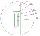
FIG. 4 is an enlarged schematic view of the structure at A in FIG. 1;
FIG. 5 is a schematic view of the structure of the connecting device;
FIG. 6 is a front view of the support plate;
FIG. 7 is a front view of the installation of the flattening rod;
FIG. 8 is a left side view schematic of the installation of the spreader beam;
FIG. 9 is a schematic top view of the spreader;
FIG. 10 is a schematic view of the structure of the clamping device;
FIG. 11 is a schematic view of the mounting structure of the guide sleeve;
FIG. 12 is a schematic view of the mounting structure of the first adjusting nut;
FIG. 13 is a schematic view of the mounting structure of the second adjusting nut;
FIG. 14 is a schematic structural view of an oven;
wherein: 1. the device comprises an uncoiling mechanism, 101, a supporting plate, 102, a switching motor, 103, a turntable, 104, a supporting shaft, 105, a second guide roller, 106, a flattening rod, 107, a driving shaft, 108, an uncoiling motor, 109, a pressing plate, 110, a supporting roller, 111, a first guide roller, 112, a film roll, 113, a blind hole, 114, a driving lever, 115, a strip-shaped groove, 116, an opening, 117, a sliding groove, 118, a compression spring, 119, a connecting block, 120, a flanging, 121, a positioning blind hole, 122, a limiting clamping ring, 2, an expander, 201, a longitudinal beam, 202, a first adjusting rack, 203, a first adjusting gear, 204, a bracket, 205, an adjusting support rod, 206, an adjusting support sleeve, 207, a tensioning sprocket, 208, a blowing fan, 209, a guiding sprocket, 210, a cooling box, 211, a second adjusting motor, 212, an oven, 213, a first adjusting screw, 214, a third adjusting motor, 215, a second adjusting screw, 216, a, Driving disc 218, conveying chain wheel 219, mounting longitudinal beam 220, adjusting rack two 221, adjusting motor four 222, supporting sliding sleeve 223, adjusting nut two 224, suction pipe 225, adjusting nut one 226, unfolding supporting beam 227, guide groove 228, air conveying pipe 229, supporting cross frame 230, blowing pipe 231, secondary cooling box 232, supporting frame plate 233, rotating rod 234, guiding sliding sleeve one 235, fixing rod 236, guiding sliding sleeve two 237, connecting rod one 238, guiding sleeve 239, rolling supporting roller 240, air distributing pipe 241, inlet 242, heat insulating layer 243, partition plate 244, buffer tank 245, heater 246, cooling fan 247, main pipe 248, air guiding pipe 249, air speed adjusting valve 250, uniform distributor plate 249, air speed adjusting valve 251, conveying pipe 252, locking bolt 253, rolling bearing 254, fixed clamping plate 255, moving clamping plate, 256. guide rod, 257, guide sleeve, 258, spring, 259, link two, 260, link four, 261, link three, 262, support plate, 263, opening driving rod, 264, rotating sleeve, 265 and clamping protrusion.
Detailed Description
The following describes embodiments of the present invention in further detail with reference to the accompanying drawings.
As shown in fig. 1 to 14, the present invention is a PTFE high strength film production apparatus, comprising a spreader 2 and an uncoiling mechanism 1 disposed at a feed end thereof, wherein the spreader 2 comprises a frame and an oven 212, the frame is provided with a pair of conveying chains 216 for clamping two sides of a film and conveying the film through the oven 212, a return end of the conveying chains 216 is disposed at an outer side of the oven 212, a plurality of cooling boxes 210 are disposed at an outer side of the return end of the conveying chains 216, each cooling box 210 is connected with a suction pipe 224, the suction pipe 224 is connected with a cooling fan 246, a secondary cooling box 231 is disposed at an outer side of a forward end of the conveying chains 216 at a front end of the oven 212, blowing pipes 230 for blowing air to the conveying chains 216 are disposed at front and rear sides of the secondary cooling box 231, the blowing pipes 230 are connected with a blowing fan 208, a suction pipe 224 connected with a cooling fan 246 is also disposed at a top of the secondary cooling box 231, the outer end of the lower part of one side supporting plate 101 is rotatably provided with a turntable 103, the turntable 103 is uniformly rotatably provided with at least two supporting shafts 104, the rear end of the turntable 103 is fixedly connected with a switching motor 102, the outer end of the lower part of the front supporting plate 101 is rotatably provided with a driving shaft 107 coaxial with the lowermost supporting shaft 104, the front end of the driving shaft 107 is fixedly connected with an uncoiling motor 108, and a connecting device is arranged between the driving shaft 107 and the lowermost supporting shaft 104. Typically 2 or 3 support shafts 104 are used, and the switching motor 102 rotates 180 degrees each time when 2 support shafts 104 are used, and the switching motor 102 rotates 120 degrees when 3 support shafts 104 are used.
The connecting device comprises a polygonal connecting block 119, a sliding groove 117 for accommodating the connecting block 119 to slide along the axial direction is formed in the inner end face of the driving shaft 107, a compression spring 118 is fixed to the bottom of the sliding groove 117, the outer end of the compression spring 118 is fixed to the connecting block 119, a strip-shaped groove 115 is formed in the side wall of the inner end of the driving shaft 107, an opening 116 communicated with the sliding groove 117 is formed in the bottom of the strip-shaped groove 115, a shifting lever 114 fixed to the connecting block 119 is arranged in the opening 116, a polygonal blind hole 113 matched with the connecting block 119 is formed in the inner end face of each supporting shaft 104.
And a second guide roller 105 and a support roller 110 are rotatably mounted on the support plate 101 between the driving shaft 107 and the first guide roller 111, the support roller 110 is positioned between the first guide roller 111 and the second guide roller 105, and the heights of the driving shaft 107, the second guide roller 105, the support roller 110 and the first guide roller 111 increase in sequence in the vertical direction.
The outer wall of the supporting roll 110 is uniformly provided with a plurality of flattening rods 106 made of elastic materials, two ends of each flattening rod 106 are provided with pressing plates 109, the outer side of the inner end of each pressing plate 109 is provided with an annular flange 120 for pressing the corresponding flattening rod 106 onto the supporting roll 110, the outer side of the inner end face of each pressing plate 109 is provided with a positioning blind hole 121 for positioning the corresponding flattening rod 106, the outer side of each pressing plate 109 is provided with a C-shaped limiting snap ring 122, the circumference of the outer end of the supporting roll 110 is provided with an annular limiting snap groove for clamping the corresponding limiting snap ring 122, and the outer end of each supporting.
The rack comprises an upper group of beams and a lower group of beams, a plurality of longitudinal beams 201 are fixed between the upper group of beams and the lower group of beams, two horizontal support frame plates 232 are arranged at the upper part of the left end of the rack, a conveying chain wheel 218 for driving a conveying chain 216 is rotatably arranged at the left end of each support frame plate 232, the conveying chain wheel 218 is connected with a conveying motor, rolling support rollers 239 capable of rolling at the top of the longitudinal beams 201 and guide sleeves 238 capable of sliding and guiding on the longitudinal beams 201 are fixed at the bottoms of the two ends of each support frame plate 232, the guide sleeves 238 and the support frame plates 232 are fixed through a first connecting rod 237, a first adjusting rack 202 is fixed on each longitudinal beam 201, a first adjusting gear 203 is meshed with the first adjusting gear 202, a first adjusting motor is fixedly connected with the first adjusting gear 203, the first adjusting motor is fixedly connected with the support frame plates 232 through a bracket 204, two splayed, the first adjusting nut 225 is connected with a first adjusting screw rod 213, and the other end of the first adjusting screw rod 213 penetrates through the oven 212 to be connected with a second adjusting motor 211.
Two parallel supporting cross frames 229 are arranged at the right end of the oven 212, a supporting sliding sleeve 222 capable of sliding back and forth is sleeved on the longitudinal beam 201 at the rightmost end, a conveying chain wheel 218 for driving the other end of the conveying chain 216 is rotatably mounted at the top of the supporting sliding sleeve 222, a conveying motor is fixedly connected with the conveying chain wheel 218, the right end of the supporting cross frame 229 is fixed with the supporting sliding sleeve 222, a third adjusting motor 214 is fixed on the right side of the supporting sliding sleeve 222, a second adjusting gear is fixedly connected with the third adjusting motor 214, the second adjusting gear is meshed with a second adjusting rack 220 which is longitudinally arranged, a longitudinal beam 219 is fixed at the right end of the second adjusting rack 220, the longitudinal beam 219 is fixed on the transverse beam, a second adjusting nut 223 is fixed at the bottom of the left end of the supporting cross frame 229, the second adjusting nut 223 is connected with a.
A plurality of clamping devices for clamping the edge of the film are uniformly arranged at the outer end of the conveying chain 216, each clamping device comprises a fixed clamping plate 254 fixed at the lower part of the outer side of the conveying chain 216, a movable clamping plate 255 is arranged at the outer side of the upper part of the fixed clamping plate 254, a guide rod 256 is fixed at the top part of the movable clamping plate 255, a guide sleeve 257 is sleeved at the outer side of the guide rod 256, a spring 258 sleeved on the guide rod 256 is arranged in the lower part of the guide sleeve 257, a second connecting rod 259 is hinged at the top part of the guide rod 256, a third connecting rod 261 is hinged at the top part of the second connecting rod 259, a rotating sleeve 264 is fixedly connected at the top part of the third connecting rod 261 and rotatably arranged on a pin shaft, the pin shaft is fixed on a support plate 262, an opening driving rod 263 is fixed at the upper part of the rotating sleeve 264, a driving disc 217 for shifting the, the clamping protrusion 265 is fixed on the conveying chain 216 through a locking bolt 252, a four-bar linkage 260 is fixed on the inner side of the guide sleeve 257, the upper end of the four-bar linkage 260 is fixed on the support plate 262, guide grooves 227 are formed in the inner sides of the support frame plate 232, the unfolding support beam 226 and the support cross frame 229, a rolling bearing 253 capable of rolling in the guide grooves is arranged in the guide grooves 227, and the rolling bearing 253 is rotatably installed at the bottom of the outer side of the conveying chain wheel 218.
The inner sides of the outer ends of the cooling boxes 210 at the left end and the right end are provided with guide chain wheels 209, the guide chain wheels 209 are rotatably arranged on a cross beam, the outer ends of the guide chain wheels 209 are provided with tensioning chain wheels 207, the tensioning chain wheels are rotatably arranged on adjusting support rods 205, the outer sides of the adjusting support rods 205 are sleeved with adjusting support sleeves 206, locking bolts 252 are arranged on the adjusting support sleeves 206, the outer sides of blowing pipes 230 are fixedly connected with air conveying pipes 228, and the air conveying pipes 228 are connected with a blowing fan 208.
The top of the adjusting nuts one 225 at both ends is fixed with a rotating rod 233, the top of the rotating rod 233 is rotatably installed at the bottom of the expanded support beam 226, the bottom of the adjusting nuts one 225 at both ends is fixed with a guide sliding sleeve one 234 sleeved on the longitudinal beam 201, the top of the adjusting nuts two 223 is fixed with a fixed rod 235, the top of the fixed rod 235 is fixed with the bottom of the left end of the support cross frame 229, and the bottom of the adjusting nuts two 223 is fixed with a guide sliding sleeve two 236 sleeved on the longitudinal beam 201.
A plurality of partition plates 243 are arranged in the oven 212, the oven 212 is divided into a plurality of sections of drying areas by the partition plates 243, an inlet 241 for the conveying chain wheel 218 to pass through is arranged on each partition plate 243 and the left and right side walls of the oven 212, a heater 245 is arranged below each inlet 241 of the plurality of sections of drying areas, a uniform distribution plate 250 is arranged at the lower end of each heater 245, air holes are uniformly arranged on the uniform distribution plate 250, an air distribution pipe 240 along the front and back direction is arranged below the uniform distribution plate 250, air outlet holes are uniformly arranged on the outer wall of the air distribution pipe 240, a conveying pipe 251 is fixed at the bottom end of the air distribution pipe 240, an air speed regulating valve 249 is arranged on the conveying pipe 251, an air guide pipe 248 is fixed at the bottom of the conveying pipe 251, a buffer tank 244 is fixedly connected with one end of the air guide pipe 248, one side, the outer side of the oven 212 and the outer side of the cooling box 210 are both provided with insulating layers 242. The discharge position of the expander 2 can be rolled by using a rolling shaft, the clamping teeth of the clamping devices on two sides are thicker due to the fact that the high-strength film is thicker during rolling, the end part is too thick easily if the high-strength film is not rolled, and later-stage processing is not facilitated, so that two sections of the high-strength film must be pressed by hands during rolling, and the two sections of the high-strength film are flattened.
When the film roll expanding device is used, a film roll 112 to be expanded is placed on the supporting shafts 104, one film roll can be placed on each supporting shaft 104, when the film roll expanding device needs to be replaced, the shifting rod 114 is shifted to enable the connecting block 119 to be separated from the blind hole 113, then the switching motor 102 drives the rotary table 103 to rotate, the next supporting shaft 104 rotates to the position matched with the driving shaft 107, the shifting rod 114 is released, the connecting block 119 is inserted into the blind hole 113 to complete connection, and quick replacement is completed, the head of the film roll 112 bypasses below the second guide roller 105, then is lapped on the flattening rod 106, is lapped on the first guide roller 111, clamps the head on the clamping device of the conveying chain 216, when the clamping device on the conveying chain 216 moves to the driving disc 217, the opening driving rod 263 can turn outwards around the pin shaft, so that the third connecting rod 261 and the second connecting rod 259 at the lower part are driven to move upwards, so that, so that enough space is reserved between the movable clamping plate 255 and the fixed clamping plate 254, a film to be widened can be placed between the movable clamping plate 255 and the fixed clamping plate 254, after the driving rod 263 is started to leave the position of the driving disk 217, the movable clamping plate 255 can clamp the edge of the film with the fixed clamping plate 254 again under the action of the spring 258, the conveying chains 216 on the two sides can be adjusted through the first adjusting motor, the second adjusting motor 211, the third adjusting motor 214 and the fourth adjusting motor 221 to adapt to different film rolls 112 and to unwind finished films with various widths, then the conveying chains 216 and the unwinding motor 108 are started, the conveying chains 216 drive the film to move from left to right, the film is heated after moving into the oven 212, and the film can be gradually stretched while being heated, so that the film is stretched to the required width in the oven 212, and the bottom of the oven 212 blows the film through wind, so that the film is in a floating state, the film is not scraped, the film is discharged under the conveying of the conveying chain 216 after exiting the oven 212, and in addition, after the conveying of the conveying chain 216 enters the return stage, the temperature on the conveying chain 216 is extracted through the cooling box 210 and the suction pipe 224 and then conveyed into the oven 212, namely, the conveying chain 216 is cooled, and the heat energy is recycled.
In summary, the return end of the conveying chain on the expander is arranged outside the oven, and then the return end of the conveying chain is matched with the cooling box arranged at the return end of the conveying chain, so that the temperature of the conveying chain can be reduced through air suction cooling, the phenomenon that the temperature is too high and the expanding quality of a product is affected because the conveying chain is located in the oven for a long time is avoided, in addition, an uncoiling mechanism and an automatic edge-closing coiling mechanism which can conveniently and quickly change coils are respectively arranged on the two sides of the inlet and the outlet of the expander, the film coils can be quickly unfolded, the edges of the thin edge-closing coiling part can be automatically closed, and the efficiency is improved.
In the description of the present invention, the terms "inside", "outside", "longitudinal", "lateral", "up", "down", "top", "bottom", and the like indicate orientations or positional relationships based on those shown in the drawings, and are for convenience only to describe the present invention without requiring the present invention to be necessarily constructed and operated in a specific orientation, and thus, should not be construed as limiting the present invention.
Claims (10)
1. The utility model provides a PTFE high strength membrane apparatus for producing, includes spreader (2) and sets up unwinding mechanism (1) at its feed end, and spreader (2) include frame and oven (212), are equipped with a pair of transport chain (216) of carrying the film both sides and passing oven (212) in the frame, its characterized in that: the return end of the conveying chain (216) is positioned on the outer side of the oven (212), a plurality of sections of cooling boxes (210) are arranged on the outer side of the return end of the conveying chain (216), a suction pipe (224) is connected to each section of cooling box (210), a cooling fan (246) is connected to each suction pipe (224), a secondary cooling box (231) is arranged on the outer side of the progress end of the conveying chain (216) at the front end of the oven (212), blowing pipes (230) facing the conveying chain (216) for blowing air are arranged on the front side and the rear side of each secondary cooling box (231), each blowing pipe (230) is connected with a blowing fan (208), the suction pipe (224) connected with the cooling fan (246) is also arranged on the top of each secondary cooling box (231), the uncoiling mechanism (1) comprises two parallel supporting plates (101), a rotary table (103) is rotatably arranged at the outer end of the lower portion of one supporting plate (101), at least, the rear end of the rotary table (103) is fixedly connected with a switching motor (102), the outer end of the lower portion of the supporting plate (101) on the front side is rotatably provided with a driving shaft (107) coaxial with the support shaft (104) on the lowest portion, the front end of the driving shaft (107) is fixedly connected with an uncoiling motor (108), and a connecting device is arranged between the driving shaft (107) and the support shaft (104) on the lowest portion.
2. The PTFE high strength membrane production device of claim 1, wherein: connecting device includes polygonal connecting block (119), be equipped with on the inner terminal surface of drive shaft (107) and hold connecting block (119) along axially sliding's spout (117), spout (117) bottom is fixed with compression spring (118), compression spring (118) outer end is fixed with connecting block (119), be equipped with bar groove (115) on the inner lateral wall of drive shaft (107), the bottom of bar groove (115) is equipped with opening (116) of intercommunication spout (117), be equipped with driving lever (114) of fixing on connecting block (119) in opening (116), be equipped with polygonal blind hole (113) of cooperation connecting block (119) on the inner terminal surface of every back shaft (104), guide roll (111) are installed in the rotation of the top inner of two backup pads (101).
3. The PTFE high strength membrane production device of claim 2, wherein: and a second guide roller (105) and a support roller (110) are rotatably mounted on the support plate (101) between the driving shaft (107) and the first guide roller (111), the support roller (110) is positioned between the first guide roller (111) and the second guide roller (105), and the heights of the driving shaft (107), the second guide roller (105), the support roller (110) and the first guide roller (111) are sequentially increased in the vertical direction.
4. The PTFE high strength membrane production device of claim 3, wherein: evenly distributed has flattening pole (106) of a plurality of elastic material preparation on the outer wall of backing roll (110), the both ends of flattening pole (106) are equipped with clamp plate (109), the inner outside of clamp plate (109) is equipped with annular turn-ups (120) that compress tightly flattening pole (106) on backing roll (110), the interior terminal surface outside of clamp plate (109) is equipped with location blind hole (121) that are used for fixing a position flattening pole (106), the outside of clamp plate (109) is equipped with spacing snap ring (122) of C type, be equipped with the annular spacing draw-in groove that is used for blocking spacing snap ring (122) on the outer end circumference of backing roll (110), backup pad (101) are less than inner echelonment setting for the outer end.
5. The PTFE high strength membrane production device of claim 4, wherein: the frame comprises an upper group of transverse beams and a lower group of transverse beams, a plurality of longitudinal beams (201) are fixed between the upper group of transverse beams and the lower group of transverse beams, two horizontal support frame plates (232) are arranged at the upper part of the left end of the frame, a conveying chain wheel (218) for driving a conveying chain (216) is rotatably installed at the left end of each support frame plate (232), the conveying chain wheel (218) is connected with a conveying motor, rolling support rollers (239) capable of rolling at the tops of the longitudinal beams (201) and guide sleeves (238) capable of sliding and guiding on the longitudinal beams (201) are fixed at the bottoms of the two ends of each support frame plate (232), the guide sleeves (238) and the support frame plates (232) are fixed through first connecting rods (237), first adjusting racks (202) are fixed on the longitudinal beams (201), the first adjusting racks (202) are meshed with first adjusting gears (203), the first adjusting gears (203) are fixedly connected with, two splayed unfolding support beams (226) are arranged on the left side of the oven (212), adjusting nuts (225) are arranged at the bottoms of the two ends of the unfolding support beams (226), the adjusting nuts (225) are connected with adjusting screws (213), and the other ends of the adjusting screws (213) penetrate through the oven (212) and are connected with adjusting motors (211).
6. The PTFE high strength membrane production device of claim 5, wherein: two parallel supporting cross frames (229) are arranged at the right end of the oven (212), a supporting sliding sleeve (222) capable of sliding back and forth is sleeved on a longitudinal beam (201) at the rightmost end, a conveying chain wheel (218) for driving the other end of a conveying chain (216) is rotatably mounted at the top of the supporting sliding sleeve (222), a conveying motor is fixedly connected with the conveying chain wheel (218), the right end of the supporting cross frame (229) is fixed with the supporting sliding sleeve (222), a third adjusting motor (214) is fixed on the right side of the supporting sliding sleeve (222), a second adjusting gear is fixedly connected with the third adjusting motor (214), a second adjusting gear (220) which is longitudinally arranged is meshed with the second adjusting gear, a mounting longitudinal beam (219) is fixed at the right end of the second adjusting gear (220), the longitudinal beam (219) is fixed on a transverse beam, a second adjusting nut (223) is fixed at the bottom of the left end of the supporting cross frame, the other end of the second adjusting screw rod (215) penetrates through the oven (212) and is connected with a fourth adjusting motor (221).
7. The PTFE high strength membrane production device of claim 6, wherein: the outer end of the conveying chain (216) is uniformly provided with a plurality of clamping devices for clamping the edge part of a film, each clamping device comprises a fixed clamping plate (254) fixed at the lower part of the outer side of the conveying chain (216), a movable clamping plate (255) is arranged at the outer side above the fixed clamping plate (254), a guide rod (256) is fixed at the top of the movable clamping plate (255), a guide sleeve (257) is sleeved at the outer side of the guide rod (256), a spring (258) sleeved on the guide rod (256) is arranged in the lower part of the guide sleeve (257), a second connecting rod (259) is hinged at the top of the guide rod (256), a third connecting rod (261) is hinged at the top of the second connecting rod (259), a rotating sleeve (264) is fixedly connected at the top of the third connecting rod (261), the rotating sleeve (264) is rotatably arranged on a pin shaft, the pin shaft is fixed on the supporting plate (262), an opening driving rod (263) is fixed at the upper part of the rotating sleeve, the inboard of extension board (262) is equipped with joint arch (265), carry chain (216) upper portion outside to be equipped with joint arch (265) complex joint recess, joint arch (265) are fixed on carrying chain (216) through locking bolt (252), guide pin bushing (257) inboard is fixed with connecting rod four (260), connecting rod four (260) upper end is fixed on extension board (262), support frame plate (232), the inboard of expansion supporting beam (226) and support crossbearer (229) all is equipped with guide slot (227), be equipped with rolling bearing (253) that can be in it in guide slot (227), rolling bearing (253) rotate to be installed in the outside bottom of carrying sprocket (218).
8. The PTFE high strength membrane production device of claim 7, wherein: the inner sides of the outer ends of the cooling boxes (210) at the left end and the right end are provided with guide chain wheels (209), the guide chain wheels (209) are rotatably installed on the cross beam, the outer ends of the guide chain wheels (209) are provided with tensioning chain wheels (207), the tensioning chain wheels are rotatably installed on the adjusting supporting rods (205), the outer side of each adjusting supporting rod (205) is sleeved with an adjusting supporting sleeve (206), each adjusting supporting sleeve (206) is provided with a locking bolt (252), the outer side of each blowing pipe (230) is fixedly connected with a blowing pipe (228), and each blowing pipe (228) is connected with a blowing fan (208).
9. The PTFE high strength membrane production device of claim 8, wherein: the top of the first adjusting nuts (225) at the two ends is fixed with a rotating rod (233), the top end of the rotating rod (233) is rotatably installed at the bottom of the unfolded supporting beam (226), the bottom of the first adjusting nuts (225) at the two ends is fixed with a first guide sliding sleeve (234) sleeved on the longitudinal beam (201), the top of the second adjusting nut (223) is fixed with a fixed rod (235), the top of the fixed rod (235) is fixed with the bottom of the left end of the supporting cross frame (229), and the bottom of the second adjusting nut (223) is fixed with a second guide sliding sleeve (236) sleeved on the longitudinal beam (201).
10. The PTFE high strength membrane production device of claim 9, wherein: a plurality of clapboards (243) are arranged in the oven (212), the clapboards (243) divide the oven (212) into a plurality of sections of drying areas, inlets (241) for the transmission chain wheel (218) to pass through are respectively arranged on the left side wall and the right side wall of each clapboard (243) and the oven (212), heaters (245) are respectively arranged below the inlets (241) of each plurality of sections of drying areas, the lower end of each heater (245) is provided with a uniform distribution plate (250), air holes are uniformly arranged on the uniform distribution plates (250), an air distribution pipe (240) along the front-back direction is arranged below the uniform distribution plates (250), air outlet holes are uniformly arranged on the outer wall of the air distribution pipe (240), a conveying pipe (251) is fixed at the bottom end of the air distribution pipe (240), an air speed regulating valve (249) is arranged on the conveying pipe (251), an air guide pipe (248) is fixed at the bottom of the conveying pipe, one side of the upper part of the buffer tank (244) is connected with a cooling fan (246) through a pipeline, an air inlet of the cooling fan (246) is connected with a main pipeline (247), the main pipeline (247) is connected with a suction pipe (224), and the outer side of the drying oven (212) and the outer side of the cooling box (210) are both provided with a heat preservation layer (242).
Priority Applications (1)
| Application Number | Priority Date | Filing Date | Title |
|---|---|---|---|
| CN202110112092.2A CN112720961B (en) | 2021-01-27 | 2021-01-27 | PTFE high strength membrane apparatus for producing |
Applications Claiming Priority (1)
| Application Number | Priority Date | Filing Date | Title |
|---|---|---|---|
| CN202110112092.2A CN112720961B (en) | 2021-01-27 | 2021-01-27 | PTFE high strength membrane apparatus for producing |
Publications (2)
| Publication Number | Publication Date |
|---|---|
| CN112720961A true CN112720961A (en) | 2021-04-30 |
| CN112720961B CN112720961B (en) | 2022-04-12 |
Family
ID=75593652
Family Applications (1)
| Application Number | Title | Priority Date | Filing Date |
|---|---|---|---|
| CN202110112092.2A Active CN112720961B (en) | 2021-01-27 | 2021-01-27 | PTFE high strength membrane apparatus for producing |
Country Status (1)
| Country | Link |
|---|---|
| CN (1) | CN112720961B (en) |
Cited By (1)
| Publication number | Priority date | Publication date | Assignee | Title |
|---|---|---|---|---|
| CN117466039A (en) * | 2023-12-28 | 2024-01-30 | 常州龙骏天纯环保科技有限公司 | Film conveying device and method for starch-based plastic sheet film |
Citations (13)
| Publication number | Priority date | Publication date | Assignee | Title |
|---|---|---|---|---|
| DE19935324A1 (en) * | 1999-07-28 | 2001-02-01 | Wolff Walsrode Ag | Film, comprises a layer(s) of polyamide comprising polyamide 6 dispersed nano-scale nucleating particles |
| CN102208586A (en) * | 2011-04-18 | 2011-10-05 | 上海乾呈玩具科技有限公司 | Method and system for preparing dynamic lithium ion battery diaphragm |
| CN102320126A (en) * | 2011-09-01 | 2012-01-18 | 山东通佳机械有限公司 | Adjustable plastic netting material transversal stretching device |
| CN102514962A (en) * | 2012-01-06 | 2012-06-27 | 广东达诚机械有限公司 | Coil replacing mechanism |
| CN202517716U (en) * | 2012-03-21 | 2012-11-07 | 湖州森诺氟材料科技有限公司 | Machine for drawing polytetrafluoroethylene micro-porous film in transverse direction |
| CN204235884U (en) * | 2014-09-26 | 2015-04-01 | 天津世起科技发展有限公司 | A kind of transversal stretching device of polyester film |
| CN205600803U (en) * | 2016-04-25 | 2016-09-28 | 孙建涛 | A earnestly install for double layer of plastic film |
| CN207001831U (en) * | 2017-06-30 | 2018-02-13 | 东莞市豪顺精密科技有限公司 | A kind of flattening bar of edge banding machine feeding |
| CN107775948A (en) * | 2016-08-26 | 2018-03-09 | 江苏华强印染机械有限公司 | A kind of inside and outside two-orbit circulatory system |
| CN109132693A (en) * | 2018-10-19 | 2019-01-04 | 浙江精力玛智能机械有限公司 | A kind of knitting tentering machine and its paving cloth method |
| CN109941796A (en) * | 2019-05-10 | 2019-06-28 | 新乡市潞旺胶粘制品有限公司 | A kind of automatic adhesive tape winding machine |
| CN210456804U (en) * | 2019-09-18 | 2020-05-05 | 滁州市光威化工有限公司 | Equipment of rolling up of non-setting adhesive tape |
| CN213833822U (en) * | 2020-12-03 | 2021-07-30 | 天津裕坤包装制品股份有限公司 | But device of quick replacement mould on inflation film manufacturing machine |
-
2021
- 2021-01-27 CN CN202110112092.2A patent/CN112720961B/en active Active
Patent Citations (13)
| Publication number | Priority date | Publication date | Assignee | Title |
|---|---|---|---|---|
| DE19935324A1 (en) * | 1999-07-28 | 2001-02-01 | Wolff Walsrode Ag | Film, comprises a layer(s) of polyamide comprising polyamide 6 dispersed nano-scale nucleating particles |
| CN102208586A (en) * | 2011-04-18 | 2011-10-05 | 上海乾呈玩具科技有限公司 | Method and system for preparing dynamic lithium ion battery diaphragm |
| CN102320126A (en) * | 2011-09-01 | 2012-01-18 | 山东通佳机械有限公司 | Adjustable plastic netting material transversal stretching device |
| CN102514962A (en) * | 2012-01-06 | 2012-06-27 | 广东达诚机械有限公司 | Coil replacing mechanism |
| CN202517716U (en) * | 2012-03-21 | 2012-11-07 | 湖州森诺氟材料科技有限公司 | Machine for drawing polytetrafluoroethylene micro-porous film in transverse direction |
| CN204235884U (en) * | 2014-09-26 | 2015-04-01 | 天津世起科技发展有限公司 | A kind of transversal stretching device of polyester film |
| CN205600803U (en) * | 2016-04-25 | 2016-09-28 | 孙建涛 | A earnestly install for double layer of plastic film |
| CN107775948A (en) * | 2016-08-26 | 2018-03-09 | 江苏华强印染机械有限公司 | A kind of inside and outside two-orbit circulatory system |
| CN207001831U (en) * | 2017-06-30 | 2018-02-13 | 东莞市豪顺精密科技有限公司 | A kind of flattening bar of edge banding machine feeding |
| CN109132693A (en) * | 2018-10-19 | 2019-01-04 | 浙江精力玛智能机械有限公司 | A kind of knitting tentering machine and its paving cloth method |
| CN109941796A (en) * | 2019-05-10 | 2019-06-28 | 新乡市潞旺胶粘制品有限公司 | A kind of automatic adhesive tape winding machine |
| CN210456804U (en) * | 2019-09-18 | 2020-05-05 | 滁州市光威化工有限公司 | Equipment of rolling up of non-setting adhesive tape |
| CN213833822U (en) * | 2020-12-03 | 2021-07-30 | 天津裕坤包装制品股份有限公司 | But device of quick replacement mould on inflation film manufacturing machine |
Cited By (2)
| Publication number | Priority date | Publication date | Assignee | Title |
|---|---|---|---|---|
| CN117466039A (en) * | 2023-12-28 | 2024-01-30 | 常州龙骏天纯环保科技有限公司 | Film conveying device and method for starch-based plastic sheet film |
| CN117466039B (en) * | 2023-12-28 | 2024-04-05 | 常州龙骏天纯环保科技有限公司 | Film conveying device and method for starch-based plastic sheet film |
Also Published As
| Publication number | Publication date |
|---|---|
| CN112720961B (en) | 2022-04-12 |
Similar Documents
| Publication | Publication Date | Title |
|---|---|---|
| CN112936834B (en) | Bidirectional stretching equipment for producing PTFE (polytetrafluoroethylene) ultra-precise filtering membrane | |
| CN101660253B (en) | Novel pilot test setter | |
| CN201614194U (en) | Coiling machine | |
| NO142227B (en) | METHOD OF PREPARING ANTIBIOTICUM THIENAMYCIN | |
| CN114178123B (en) | Transparent adhesive tape production and processing system and processing method | |
| CN112720961B (en) | PTFE high strength membrane apparatus for producing | |
| CN206288756U (en) | A kind of non-woven fabric bag buffer storage | |
| JP4063952B2 (en) | Drawer device for tube webs made of plastic sheets | |
| CN210588120U (en) | Automatic production system for large-diameter steel pipe | |
| CN102765242A (en) | Aqueous synthetic leather production line | |
| CN106319808A (en) | Cloth ironing processing cloth discharging flow line | |
| CN109927264A (en) | A kind of light guide plate hot-rolling pressing production line and hot rolling process | |
| CN114311940B (en) | Antibacterial anti-fouling surface fabric processing is with hot pressing composite mechanism | |
| CN206936230U (en) | A kind of spring coiling machine of hot coiling springs | |
| CN112793136B (en) | PTFE nanometer membrane production facility | |
| CN210589761U (en) | Floor hot press with discharging device | |
| CN112936832B (en) | PTFE electronic film production expander | |
| CN113477481A (en) | Coating machine | |
| CN205871311U (en) | Weave cloth automatic coating all -in -one | |
| CN206661981U (en) | A kind of straightener | |
| CN214140826U (en) | Draw gear is used in PE membrane production | |
| WO2018064787A1 (en) | Printing paper release system apparatus | |
| CN209009764U (en) | A kind of automatic Song Buji | |
| CN111979668A (en) | Energy-saving intelligent production equipment for sizing knitted fabric and plain woven fabric | |
| CN209305937U (en) | A kind of film feeder of foods packing machine |
Legal Events
| Date | Code | Title | Description |
|---|---|---|---|
| PB01 | Publication | ||
| PB01 | Publication | ||
| SE01 | Entry into force of request for substantive examination | ||
| SE01 | Entry into force of request for substantive examination | ||
| GR01 | Patent grant | ||
| GR01 | Patent grant |