CN112720420A - Double-guide-rail type planar robot with parallelogram - Google Patents
Double-guide-rail type planar robot with parallelogram Download PDFInfo
- Publication number
- CN112720420A CN112720420A CN202110037699.9A CN202110037699A CN112720420A CN 112720420 A CN112720420 A CN 112720420A CN 202110037699 A CN202110037699 A CN 202110037699A CN 112720420 A CN112720420 A CN 112720420A
- Authority
- CN
- China
- Prior art keywords
- curve guide
- guide rail
- plane
- plane curve
- sliding block
- Prior art date
- Legal status (The legal status is an assumption and is not a legal conclusion. Google has not performed a legal analysis and makes no representation as to the accuracy of the status listed.)
- Granted
Links
Images


Classifications
-
- B—PERFORMING OPERATIONS; TRANSPORTING
- B25—HAND TOOLS; PORTABLE POWER-DRIVEN TOOLS; MANIPULATORS
- B25J—MANIPULATORS; CHAMBERS PROVIDED WITH MANIPULATION DEVICES
- B25J9/00—Programme-controlled manipulators
- B25J9/003—Programme-controlled manipulators having parallel kinematics
- B25J9/0045—Programme-controlled manipulators having parallel kinematics with kinematics chains having a rotary joint at the base
-
- B—PERFORMING OPERATIONS; TRANSPORTING
- B25—HAND TOOLS; PORTABLE POWER-DRIVEN TOOLS; MANIPULATORS
- B25J—MANIPULATORS; CHAMBERS PROVIDED WITH MANIPULATION DEVICES
- B25J19/00—Accessories fitted to manipulators, e.g. for monitoring, for viewing; Safety devices combined with or specially adapted for use in connection with manipulators
-
- B—PERFORMING OPERATIONS; TRANSPORTING
- B25—HAND TOOLS; PORTABLE POWER-DRIVEN TOOLS; MANIPULATORS
- B25J—MANIPULATORS; CHAMBERS PROVIDED WITH MANIPULATION DEVICES
- B25J5/00—Manipulators mounted on wheels or on carriages
- B25J5/02—Manipulators mounted on wheels or on carriages travelling along a guideway
Abstract
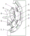
A double-guide-rail type planar robot comprising a parallelogram comprises a fixed platform, a moving platform and three branched chains which are connected between the fixed platform and the moving platform and have the same structure, wherein a section of planar curve guide rail I is arranged on the fixed platform, the moving platform is fixedly connected with three sections of planar curve guide rails II, each section of planar curve guide rail II is connected with the planar curve guide rail I through one branched chain, each branched chain comprises a sliding block I, two connecting rods which are arranged in parallel and a sliding block II, the sliding block I is connected with the planar curve guide rail I in a sliding mode, the sliding block I is rotatably connected with one end of each connecting rod through a revolute pair I, the other end of each connecting rod is rotatably connected with the sliding block II through a revolute pair II, and the sliding block II is connected with the planar curve; three sliders II or three sliders I are used as driving members.
Description
Technical Field
The invention relates to the technical field of robots, in particular to a double-guide-rail type plane robot comprising a parallelogram.
Background
The parallel robot has the characteristics of high rigidity, high bearing capacity, high precision, small motion load, easiness in inverse solution and the like, so that the parallel robot is widely applied to the aspects of motion simulators, virtual axis machine tools, somatosensory simulators, medical equipment, agricultural operation robots and the like.
For the research of the three-degree-of-freedom robot, a lot of scholars do a lot of work. The Yuesheng provides a plane parallel robot experimental device with 3 flexible hinges based on a 3-RRR parallel robot, and the device can enable a motion platform of a mechanism to realize movement along the direction of an axis X, Y and rotation around the direction of an axis Z. Herve successfully synthesizes a three-degree-of-freedom translational parallel robot, such as a 3-RRC parallel robot, based on lie group and lie algebra theory. The Huangzhen provides a comprehensive method of a parallel robot type with less degrees of freedom including a plurality of translational parallel robots with three degrees of freedom based on the principle of a spiral theory. Liqichuan utilizes a spiral theory to carry out symmetrical three-degree-of-freedom parallel robot type synthesis of the system. The peak integrates a plurality of symmetrical and asymmetrical three-freedom-degree translation parallel robots with novel structures based on GF set theory. In 2011, chenfengming et al provides a novel two-translation one-rotation RRR-URR-RR parallel robot, analyzes the motion output characteristics of the mechanism, calculates the degree of freedom, and establishes a positive and negative solution equation of the position of the parallel robot. In 2016, Jurwei et al, university of Changzhou invented a two-translation and one-rotation parallel robot, which realizes two-dimensional translation motion and one-dimensional rotation motion in space by driving a movable platform to move through three actively-driven moving pairs. In 2018, Yanshan university Liyangxi et al propose a two-translation and one-rotation 2RRR-CRR parallel robot, the mechanism only comprises a moving pair and a rotating pair (a cylindrical pair is formed by combining the moving pair and the rotating pair), and most of the mechanism is the rotating pair, so that the mechanism is simple in structure and the axis relation is easy to satisfy.
Although scholars at home and abroad provide more three-degree-of-freedom robot configuration schemes, the planar three-degree-of-freedom robot has different performance requirements in different application fields, so that the robot configuration types with two translational degrees of freedom and one rotational degree of freedom are provided as many as possible, and the method has important significance for the type selection of researchers in the field.
Disclosure of Invention
The invention aims to solve the technical problem that the prior art has the defects, and provides a double-guide-rail plane robot with a parallelogram, which has a novel structure and two translational degrees of freedom and one rotational degree of freedom.
The scheme is realized by the following technical measures: the utility model provides a contain parallelogram's double track formula planar robot, includes fixed platform, motion platform and connects three branch chains that the structure is the same between fixed platform and motion platform, be provided with one section plane curve guide rail I on the fixed platform, motion platform fixedly connected with three-section plane curve guide rail II, every section plane curve guide rail II all is connected with plane curve guide rail I through a branch chain, and every branch chain all includes slider I, two parallel arrangement's connecting rod and slider II, slider I and I sliding connection of plane curve guide rail, slider I is rotated through revolute pair I and the one end of connecting rod and is connected, the other end of connecting rod rotates through revolute pair II and slider II and is connected, slider II and II sliding connection of plane curve guide rail, in a branch chain, the distance between revolute pair I and the revolute pair II that a connecting rod both ends are connected and the revolute pair I and the revolute pair II that another connecting rod both ends are connected between revolute pair I The distances are equal; the axes of the six revolute pairs I are parallel to each other and are perpendicular to a movement plane I of the sliding block I relative to the plane curve guide rail I and a movement plane II of the sliding block II relative to the plane curve guide rail II; the axes of the six revolute pairs II are parallel to each other and are perpendicular to a movement plane I of the sliding block I relative to the plane curve guide rail I and a movement plane II of the sliding block II relative to the plane curve guide rail II; three sliding blocks II or three sliding blocks I are used as driving members; the three sections of plane curve guide rails II are arc-shaped guide rails with different circle centers.
Preferably, the length of the plane curve guide rail I is greater than the sum of the lengths of the three sections of plane curve guide rails II, and the width of the plane curve guide rail I is greater than that of the plane curve guide rails II.
Preferably, the motion platform is fixedly connected with three sections of plane curve guide rails II through three fixing rods.
Preferably, the three sliding blocks II are in the same plane or parallel planes relative to the motion plane II of the planar curve guide rail II.
Compared with the prior art, the invention has the advantages that: a section of plane curve guide rail I and a section of plane curve guide rail II are introduced into the fixed platform and the moving platform simultaneously, the sliding block I, the revolute pair I, the connecting rod, the revolute pair II and the sliding block II are matched for use, so that the robot is guaranteed to have the motion characteristics of two translational degrees of freedom and one rotational degree of freedom, the working space can be increased on the specific degree of freedom by independently increasing the length of each section of guide rail and/or the length of the connecting rod, the flexibility of the robot design is improved, the slide block I, the two connecting rods arranged in parallel and the slide block II can form a parallelogram structure, particularly, the rotating connection points of the two connecting rods, the slide block I and the slide block II are four vertexes of the parallelogram, meanwhile, three sliding blocks II in the structure can be used as a driving part, and three sliding blocks I can also be used as a driving part, so that the flexibility of selecting a driving mode of the robot is improved.
Therefore, compared with the prior art, the invention has prominent substantive features and remarkable progress, and the beneficial effects of the implementation are also obvious.
Drawings
In order to more clearly illustrate the technical solution of the present invention, the drawings used in the description will be briefly introduced, and it is obvious that the drawings in the following description are only some embodiments of the present invention, and it is obvious for those skilled in the art that other drawings can be obtained based on these drawings without creative efforts.
FIG. 1 is a schematic structural view of the present invention;
FIG. 2 is a schematic structural view of a fixed platform;
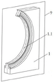
FIG. 3 is a schematic view I of a connection structure of a motion platform and a plane curve guide rail II;
fig. 4 is a schematic view of a connection structure of the motion platform and a plane curve guide rail ii.
In the figure: 1-fixed platform, 1.1-plane curve guide rail I, 2-slide block I, 3-revolute pair I, 4-connecting rod, 5-slide block II, 6-moving platform, 7-plane curve guide rail II, 8-fixed rod, 9-moving plane I, 10-moving plane II, 11-revolute pair II.
Detailed Description
In order to make the objects, features and advantages of the present invention more obvious and understandable, the technical solutions of the present invention will be clearly and completely described below with reference to specific embodiments and drawings. All other embodiments, which can be derived by a person skilled in the art from the embodiments given herein without making any creative effort, shall fall within the scope of protection of this patent.
As shown in fig. 1 and 2, a double-guide-rail planar robot comprising a parallelogram comprises a fixed platform 1, a moving platform 6 and three branched chains with the same structure connected between the fixed platform 1 and the moving platform 6, wherein a section of planar curve guide rail I1.1 is arranged on the fixed platform 1, three sections of planar curve guide rails II7 are fixedly connected with the moving platform 6, each section of planar curve guide rail II7 is connected with the planar curve guide rail I1.1 through a branched chain, each branched chain comprises a sliding block I2, two connecting rods 4 arranged in parallel and a sliding block II 5, the sliding block I2 is in sliding connection with the planar curve guide rail I1.1, the sliding block I2 is in rotating connection with one end of the connecting rod 4 through a rotating pair I3, the other end of the connecting rod 4 is in rotating connection with the sliding block II 5 through a rotating pair II 11, the sliding block II 5 is in sliding connection with the planar curve guide rail II7, in one branched chain, the distance between a revolute pair I3 and a revolute pair II 11 connected with two ends of one connecting rod 4 is equal to the distance between the revolute pair I3 and the revolute pair II 11 connected with two ends of the other connecting rod 4; the axes of the six revolute pairs I3 are parallel to each other and are perpendicular to a movement plane I9 of the sliding block I2 relative to the plane curve guide rail I1.1 and a movement plane II 10 of the sliding block II 5 relative to the plane curve guide rail II 7; the axes of the six revolute pairs II 11 are parallel to each other and are perpendicular to a movement plane I9 of the sliding block I2 relative to the plane curve guide rail I1.1 and a movement plane II 10 of the sliding block II 5 relative to the plane curve guide rail II 7; three sliding blocks II 5 or three sliding blocks I2 are used as driving members; the three sections of plane curve guide rails II7 are arc guide rails with different circle centers. Preferably, the three sections of plane curve guide rails II7 are circular arc guide rails with different centers of circles, and the plane curve guide rails I1.1 are circular arc guide rails.
The length of the plane curve guide rail I1.1 is larger than the sum of the lengths of the three sections of plane curve guide rails II7, and the width of the plane curve guide rail I1.1 is larger than the width of the plane curve guide rail II 7.
The motion platform 6 is fixedly connected with three sections of plane curve guide rails II7 through three fixing rods 8.
In the technical scheme, the three branched chains with the same structure mean that components contained in the three branched chains and the connection relationship among the components are the same, but the sizes of the same components in the three branched chains can be different.
Fig. 2 shows the plane of movement I9 of the slide I2 relative to the planar curved guide I1.1.
As shown in fig. 3-4, the three sliding blocks II 5 are respectively the same plane or parallel planes with respect to the three motion planes II 10 of the three-section plane curve guide rail II 7.
In the technical scheme, a plane curve guide rail I1.1 is characterized in that a sliding block I2 does plane curve motion along the guide rail as the name implies; the plane curve guide rail II7 is characterized in that the sliding block II 5 does plane curve motion along the guide rail as the name implies.
The embodiments in the present description are described in a progressive manner, each embodiment focuses on differences from other embodiments, and the same and similar parts among the embodiments are referred to each other.
The previous description of the disclosed embodiments is provided to enable any person skilled in the art to make or use the present invention. Various modifications to these embodiments will be readily apparent to those skilled in the art, and the generic principles defined herein may be applied to other embodiments without departing from the spirit or scope of the invention. Thus, the present invention is not intended to be limited to the embodiments shown herein but is to be accorded the widest scope consistent with the principles and novel features and inventive features disclosed herein.
Claims (4)
1. The utility model provides a two guide rail formula planar robot that contain parallelogram, includes fixed platform (1), motion platform (6) and connects three branch chains that the structure is the same between fixed platform (1) and motion platform (6), its characterized in that: be provided with one section plane curve guide rail I (1.1) on fixed platform (1), motion platform (6) fixedly connected with three-section plane curve guide rail II (7), every section plane curve guide rail II (7) all are connected with plane curve guide rail I (1.1) through a branch chain, and every branch chain all includes slider I (2), two parallel arrangement's connecting rod (4) and slider II (5), slider I (2) and plane curve guide rail I (1.1) sliding connection, slider I (2) rotate with the one end of connecting rod (4) through revolute pair I (3) and are connected, the other end of connecting rod (4) rotates through revolute pair II (11) and is connected with slider II (5), slider II (5) and plane curve guide rail II (7) sliding connection, in a branch chain, the distance between revolute pair I (3) and the revolute pair II (11) that a connecting rod (4) both ends are connected is connected with another connecting rod (4) both ends The distances between the revolute pair I (3) and the revolute pair II (11) are equal; the axes of the six revolute pairs I (3) are parallel to each other and are perpendicular to a movement plane I (9) of the sliding block I (2) relative to the plane curve guide rail I (1.1) and a movement plane II (10) of the sliding block II (5) relative to the plane curve guide rail II (7); the axes of the six revolute pairs II (11) are parallel to each other and are all perpendicular to a movement plane I (9) of the sliding block I (2) relative to the plane curve guide rail I (1.1) and a movement plane II (10) of the sliding block II (5) relative to the plane curve guide rail II (7); three sliding blocks II (5) or three sliding blocks I (2) are used as driving parts; the three sections of plane curve guide rails II (7) are arc guide rails with different circle centers.
2. The parallelogram-containing two-rail planar robot of claim 1, wherein: the length of the plane curve guide rail I (1.1) is greater than the sum of the lengths of the three sections of plane curve guide rails II (7), and the width of the plane curve guide rail I (1.1) is greater than the width of the plane curve guide rails II (7).
3. The parallelogram-containing two-rail planar robot of claim 1, wherein: the motion platform (6) is fixedly connected with three sections of plane curve guide rails II (7) through three fixing rods (8).
4. The parallelogram-containing two-rail planar robot of claim 1, wherein: the three sliding blocks II (5) are the same plane or parallel planes relative to the motion plane II (10) of the plane curve guide rail II (7).
Priority Applications (1)
| Application Number | Priority Date | Filing Date | Title |
|---|---|---|---|
| CN202110037699.9A CN112720420B (en) | 2021-01-12 | 2021-01-12 | Double-guide-rail type planar robot with parallelogram |
Applications Claiming Priority (1)
| Application Number | Priority Date | Filing Date | Title |
|---|---|---|---|
| CN202110037699.9A CN112720420B (en) | 2021-01-12 | 2021-01-12 | Double-guide-rail type planar robot with parallelogram |
Publications (2)
| Publication Number | Publication Date |
|---|---|
| CN112720420A true CN112720420A (en) | 2021-04-30 |
| CN112720420B CN112720420B (en) | 2022-03-25 |
Family
ID=75590511
Family Applications (1)
| Application Number | Title | Priority Date | Filing Date |
|---|---|---|---|
| CN202110037699.9A Active CN112720420B (en) | 2021-01-12 | 2021-01-12 | Double-guide-rail type planar robot with parallelogram |
Country Status (1)
| Country | Link |
|---|---|
| CN (1) | CN112720420B (en) |
Citations (7)
| Publication number | Priority date | Publication date | Assignee | Title |
|---|---|---|---|---|
| CN102009358A (en) * | 2010-11-05 | 2011-04-13 | 山东理工大学 | Annular elastic pair-containing three-degrees-of-freedom micro operating table |
| CN104308834A (en) * | 2014-10-24 | 2015-01-28 | 天津大学 | Symmetric three-rotation parallel mechanism |
| CN104308833A (en) * | 2014-10-24 | 2015-01-28 | 天津大学 | Decoupling type two-freedom-degree rotation parallel mechanism capable of achieving hemisphere rotation |
| CN105563468A (en) * | 2016-02-04 | 2016-05-11 | 陕西科技大学 | Parallel mechanical arm controlled by cams |
| CN108161899A (en) * | 2017-12-25 | 2018-06-15 | 武汉大学 | A kind of biped climbs crusing robot |
| CN110653797A (en) * | 2019-09-18 | 2020-01-07 | 北京理工大学 | Three-degree-of-freedom pneumatic translation parallel mechanism |
| US20200033211A1 (en) * | 2017-02-07 | 2020-01-30 | Technische Universität Darmstadt | Sensor arrangement for force or torque measurement, and a method for the production thereof |
-
2021
- 2021-01-12 CN CN202110037699.9A patent/CN112720420B/en active Active
Patent Citations (7)
| Publication number | Priority date | Publication date | Assignee | Title |
|---|---|---|---|---|
| CN102009358A (en) * | 2010-11-05 | 2011-04-13 | 山东理工大学 | Annular elastic pair-containing three-degrees-of-freedom micro operating table |
| CN104308834A (en) * | 2014-10-24 | 2015-01-28 | 天津大学 | Symmetric three-rotation parallel mechanism |
| CN104308833A (en) * | 2014-10-24 | 2015-01-28 | 天津大学 | Decoupling type two-freedom-degree rotation parallel mechanism capable of achieving hemisphere rotation |
| CN105563468A (en) * | 2016-02-04 | 2016-05-11 | 陕西科技大学 | Parallel mechanical arm controlled by cams |
| US20200033211A1 (en) * | 2017-02-07 | 2020-01-30 | Technische Universität Darmstadt | Sensor arrangement for force or torque measurement, and a method for the production thereof |
| CN108161899A (en) * | 2017-12-25 | 2018-06-15 | 武汉大学 | A kind of biped climbs crusing robot |
| CN110653797A (en) * | 2019-09-18 | 2020-01-07 | 北京理工大学 | Three-degree-of-freedom pneumatic translation parallel mechanism |
Non-Patent Citations (2)
| Title |
|---|
| WANG WEI等: "Research On Fault Tolerant Control Strategy of Multi-Degree-of-Freedom Manipulator with Single Joint Faults", 《2018 37TH CHINESE CONTROL CONFERENCE (CCC)》 * |
| 宫金良等: "一种 2-PPr 平面并联机构的静刚度分析", 《组合机床与自动化加工技术》 * |
Also Published As
| Publication number | Publication date |
|---|---|
| CN112720420B (en) | 2022-03-25 |
Similar Documents
| Publication | Publication Date | Title |
|---|---|---|
| CN112720423B (en) | Single-layer three-section guide rail type planar robot with double parallelograms | |
| CN100395086C (en) | Robot machanism able to achieve two-D movement and of two-freedom plane-parallel type | |
| CN208468376U (en) | A kind of redundant constaint parallel institution of space two rotation-translation | |
| CN112720424B (en) | Double-layer three-section guide rail type planar robot with parallelogram | |
| CN108858141B (en) | Space two-rotation one-translation redundancy constraint parallel mechanism and working method thereof | |
| CN210161139U (en) | 2PRU-2PUR three-degree-of-freedom redundant drive parallel mechanism | |
| CN112720420B (en) | Double-guide-rail type planar robot with parallelogram | |
| CN109079761B (en) | Two-rotation one-movement parallel robot with closed-loop branched chain | |
| CN102579137A (en) | Parallel surgical manipulator capable of horizontally moving three-dimensionally and rotating one-dimensionally | |
| CN113319811B (en) | Double-guide-rail type planar robot with revolute pairs | |
| CN113146587B (en) | Single-layer single-section guide rail type plane robot with double parallelograms | |
| CN112720421B (en) | Double-guide-rail type planar robot with telescopic rod | |
| CN113319832A (en) | Three-translation parallel mechanism with symmetrical branches | |
| CN102873681A (en) | Novel two-degree-of-freedom manipulator mechanism | |
| CN112720426A (en) | Double-layer three-section guide rail type planar robot with revolute pairs | |
| CN112720419A (en) | Single-layer three-section guide rail type planar robot with double rotating pairs | |
| CN112720425A (en) | Double-layer three-section guide rail type planar robot with telescopic rod | |
| CN112276912B (en) | Parallel mechanism containing orthogonal double-linear driving branched chain | |
| CN112428257B (en) | Six-degree-of-freedom parallel mechanism with compound driving branched chain | |
| CN208529098U (en) | Seven freedom mechanical arm | |
| CN212385478U (en) | Complete decoupling two-rotation one-movement parallel mechanism | |
| CN112008698A (en) | Two-rotation one-movement asymmetric complete decoupling parallel robot | |
| CN212497752U (en) | Two-rotation one-movement asymmetric complete decoupling parallel robot | |
| CN110481672A (en) | A kind of low degree-of-freedom omnidirectional four-footed mobile platform | |
| CN202554113U (en) | Parallel operation device capable of achieving three-dimensional translation and one-dimensional rotation |
Legal Events
| Date | Code | Title | Description |
|---|---|---|---|
| PB01 | Publication | ||
| PB01 | Publication | ||
| SE01 | Entry into force of request for substantive examination | ||
| SE01 | Entry into force of request for substantive examination | ||
| GR01 | Patent grant | ||
| GR01 | Patent grant |