CN1127184C - Status indicator for electronic device - Google Patents
Status indicator for electronic device Download PDFInfo
- Publication number
- CN1127184C CN1127184C CN99813629A CN99813629A CN1127184C CN 1127184 C CN1127184 C CN 1127184C CN 99813629 A CN99813629 A CN 99813629A CN 99813629 A CN99813629 A CN 99813629A CN 1127184 C CN1127184 C CN 1127184C
- Authority
- CN
- China
- Prior art keywords
- light
- light source
- connector plug
- electronic equipment
- socket
- Prior art date
- Legal status (The legal status is an assumption and is not a legal conclusion. Google has not performed a legal analysis and makes no representation as to the accuracy of the status listed.)
- Expired - Fee Related
Links
Images
Classifications
-
- H—ELECTRICITY
- H01—ELECTRIC ELEMENTS
- H01R—ELECTRICALLY-CONDUCTIVE CONNECTIONS; STRUCTURAL ASSOCIATIONS OF A PLURALITY OF MUTUALLY-INSULATED ELECTRICAL CONNECTING ELEMENTS; COUPLING DEVICES; CURRENT COLLECTORS
- H01R31/00—Coupling parts supported only by co-operation with counterpart
- H01R31/06—Intermediate parts for linking two coupling parts, e.g. adapter
-
- H—ELECTRICITY
- H01—ELECTRIC ELEMENTS
- H01R—ELECTRICALLY-CONDUCTIVE CONNECTIONS; STRUCTURAL ASSOCIATIONS OF A PLURALITY OF MUTUALLY-INSULATED ELECTRICAL CONNECTING ELEMENTS; COUPLING DEVICES; CURRENT COLLECTORS
- H01R13/00—Details of coupling devices of the kinds covered by groups H01R12/70 or H01R24/00 - H01R33/00
- H01R13/66—Structural association with built-in electrical component
- H01R13/717—Structural association with built-in electrical component with built-in light source
- H01R13/7172—Conduits for light transmission
-
- H—ELECTRICITY
- H05—ELECTRIC TECHNIQUES NOT OTHERWISE PROVIDED FOR
- H05K—PRINTED CIRCUITS; CASINGS OR CONSTRUCTIONAL DETAILS OF ELECTRIC APPARATUS; MANUFACTURE OF ASSEMBLAGES OF ELECTRICAL COMPONENTS
- H05K5/00—Casings, cabinets or drawers for electric apparatus
- H05K5/02—Details
- H05K5/0256—Details of interchangeable modules or receptacles therefor, e.g. cartridge mechanisms
- H05K5/026—Details of interchangeable modules or receptacles therefor, e.g. cartridge mechanisms having standardized interfaces
- H05K5/0265—Details of interchangeable modules or receptacles therefor, e.g. cartridge mechanisms having standardized interfaces of PCMCIA type
- H05K5/0273—Details of interchangeable modules or receptacles therefor, e.g. cartridge mechanisms having standardized interfaces of PCMCIA type having extensions for peripherals, e.g. LAN, antennas
-
- H—ELECTRICITY
- H01—ELECTRIC ELEMENTS
- H01R—ELECTRICALLY-CONDUCTIVE CONNECTIONS; STRUCTURAL ASSOCIATIONS OF A PLURALITY OF MUTUALLY-INSULATED ELECTRICAL CONNECTING ELEMENTS; COUPLING DEVICES; CURRENT COLLECTORS
- H01R13/00—Details of coupling devices of the kinds covered by groups H01R12/70 or H01R24/00 - H01R33/00
- H01R13/66—Structural association with built-in electrical component
- H01R13/665—Structural association with built-in electrical component with built-in electronic circuit
- H01R13/6691—Structural association with built-in electrical component with built-in electronic circuit with built-in signalling means
-
- H—ELECTRICITY
- H01—ELECTRIC ELEMENTS
- H01R—ELECTRICALLY-CONDUCTIVE CONNECTIONS; STRUCTURAL ASSOCIATIONS OF A PLURALITY OF MUTUALLY-INSULATED ELECTRICAL CONNECTING ELEMENTS; COUPLING DEVICES; CURRENT COLLECTORS
- H01R13/00—Details of coupling devices of the kinds covered by groups H01R12/70 or H01R24/00 - H01R33/00
- H01R13/66—Structural association with built-in electrical component
- H01R13/717—Structural association with built-in electrical component with built-in light source
-
- H—ELECTRICITY
- H01—ELECTRIC ELEMENTS
- H01R—ELECTRICALLY-CONDUCTIVE CONNECTIONS; STRUCTURAL ASSOCIATIONS OF A PLURALITY OF MUTUALLY-INSULATED ELECTRICAL CONNECTING ELEMENTS; COUPLING DEVICES; CURRENT COLLECTORS
- H01R24/00—Two-part coupling devices, or either of their cooperating parts, characterised by their overall structure
- H01R24/60—Contacts spaced along planar side wall transverse to longitudinal axis of engagement
- H01R24/62—Sliding engagements with one side only, e.g. modular jack coupling devices
- H01R24/64—Sliding engagements with one side only, e.g. modular jack coupling devices for high frequency, e.g. RJ 45
-
- H—ELECTRICITY
- H01—ELECTRIC ELEMENTS
- H01R—ELECTRICALLY-CONDUCTIVE CONNECTIONS; STRUCTURAL ASSOCIATIONS OF A PLURALITY OF MUTUALLY-INSULATED ELECTRICAL CONNECTING ELEMENTS; COUPLING DEVICES; CURRENT COLLECTORS
- H01R27/00—Coupling parts adapted for co-operation with two or more dissimilar counterparts
-
- Y—GENERAL TAGGING OF NEW TECHNOLOGICAL DEVELOPMENTS; GENERAL TAGGING OF CROSS-SECTIONAL TECHNOLOGIES SPANNING OVER SEVERAL SECTIONS OF THE IPC; TECHNICAL SUBJECTS COVERED BY FORMER USPC CROSS-REFERENCE ART COLLECTIONS [XRACs] AND DIGESTS
- Y10—TECHNICAL SUBJECTS COVERED BY FORMER USPC
- Y10S—TECHNICAL SUBJECTS COVERED BY FORMER USPC CROSS-REFERENCE ART COLLECTIONS [XRACs] AND DIGESTS
- Y10S439/00—Electrical connectors
- Y10S439/91—Observation aide, e.g. transparent material, window in housing
Landscapes
- Engineering & Computer Science (AREA)
- Microelectronics & Electronic Packaging (AREA)
- Details Of Connecting Devices For Male And Female Coupling (AREA)
- Devices For Indicating Variable Information By Combining Individual Elements (AREA)
- Illuminated Signs And Luminous Advertising (AREA)
- Connector Housings Or Holding Contact Members (AREA)
- Coupling Device And Connection With Printed Circuit (AREA)
- Fastening Of Light Sources Or Lamp Holders (AREA)
- Optical Couplings Of Light Guides (AREA)
Abstract
An electronic device adapted to be coupled to an information transfer system by means of a conductor including a standard connector having a translucent or transparent body insertable into a receptacle defined by the electronic device, the device including a housing, a substrate carrying electronic components, a light source mounted on the substrate and connected to components on the substrate, the light source being energizable in response to electrical signals generated by said components, the signals being indicative of the status and/or activity of the device, and a light guide extending between the light source and the receptacle for transmitting light from the light source to the receptacle, the light transmitted from the source to the receptacle illuminating the connector body thereby providing an indication of the status and/or activity of the electronic device.
Description
Interleaving techniques to related application is quoted
This application has been declared the advantage of No. the 60/101st, 678, the U.S. Provisional Application submitted on September 24th, 1998.This application still is the 08/971st, No. 501 application of submitting on November 17th, 1997 and 09/048,143 further part of submitting on March 25th, 1998 of applying for, quotes latter two application herein.
Background technology of the present invention
The technical field of the invention
The present invention relates to show the state of electronic equipment and the indicating device of behavior, this electronic equipment for example provides telephone wire and/or the communication PC card that is connected of LAN;
Description of the Prior Art
The PC card is the equipment that is inserted in the main electronic system groove.According to the kind difference of main system groove, these cards are followed various physics and electrical specification.Be disclosed in June 30 in 1998 purpose United States Patent (USP)s 5,773,332 a kind of communication card of the III of following class PCMCIA PC calliper lattice has been described.See the Figure 21 and the content of ' 332 patent for details from the 15th hurdle the 53rd row to the 16th hurdle the 11st row.The communication card of ' 332 patent is sold by Tantivy (U.S.A) Co. of California thousand rubbers (ThousandOaks), and trade mark is " RealPort ".
Be used as 68 needle connectors that the pcmcia card that communicates to connect comprises base in inner room, the inner room or printed circuit board (PCB), inner room front panel usually, it is used for connecting this and snaps into main system, and at least one socket that is positioned at the inner room rear board, be used for connecting this and snap into the information transmission system for example telephone wire or LAN.Be depicted as the representative of this card of prior art as 10 among Fig. 1.According to prior art, being assembled on base or the PCB is one group of state or behavior LED (for example 4) that different colours is arranged.Each LED has the light tunnel of a correspondence, and from an other end 12 that extends to the light tunnel outside near the light tunnel of LED, it is arranged in the cannelure 14 near the card outer surface of upper of rear board.The state of LED indicator card 10 and behavior, and when being illuminated, can be seen by the user through relevant light tunnel from the light of these LED.Light tunnel indicating device 12 can be used to show that Ethernet connects and data flow, and modem carrier signal and by by electrical connector plug 16 with the data transmission/accepting activity that carries out of the electrical connection that is positioned at the socket 18 of card 10 rear boards and provides.
The invention summary
Target of the present invention is to improve the state that uses on the PC card and the arrangement of behavior indicator light.Light source is preferentially selected LED for use, is mounted to the printed circuit board (PCB) of PC card and is connected to suitable circuit element, thereby be activated and the luminous state/activity that responds the signal of telecommunication with indicator card.Light tunnel between LED and socket provides optical coupling, and this socket has one at least, is used for the communication plug of acceptance criteria RJ-xx type, for example RJ-11 or RJ-45 plug.Thereby the RJ-xx plug preferably includes the transparent or semitransparent entity of acrylic component and is used for being illuminated from the transmission of socket end or the light conducting of light tunnel.LED illuminates the entity of RJ-xx plug through light tunnel, thereby state and behavioural information are provided.The a plurality of LED with different colours and the light tunnel of respective amount thereof can be provided.
Provide between electronic equipment and external system according to connected system of the present invention and to be electrically connected and to comprise: (1) pluggable electrical connector plug with the equipment of visible mode indicating status and behavior, one or more electric contact point pieces are arranged in its transparent entity, (2) light source of electronic equipment driving, light source luminescent is indicated the state of electronic equipment, (3) light tunnel of first and second ends is arranged, light is sent to second end from first end, first end of light tunnel and light source are approaching so that realize optical coupling, (4) electrical outlet, when connector plug inserts this socket, it can provide one or more signals of telecommunication to pluggable electrical connector plug from electronic equipment, second end of light tunnel is coupled to this electrical outlet, and it provides the transparent entity of the electric connector that throws light on from light tunnel after connector plug inserts this socket.
According to another embodiment of the invention, can not want light tunnel, directly one or more light sources directly are assembled on the opening of the contact piece corresponding with each socket.
In another embodiment of the present invention, connector and socket are followed the specification of RJ-11 or RJ-45 connector.In another embodiment of the present invention, one group of light source and light tunnel are used to provide to the various states of the electronic equipment that drives this light source or the indication of behavior.In addition, light source is preferentially selected the LED form for use.
Novel features of the present invention is described in conjunction with claims.In the following description, can better understand the present invention in conjunction with the accompanying drawings.
Accompanying drawing is briefly described
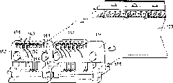
Fig. 1 is the perspective view of the PCMAIA card of prior art, has visible indicating device to be assemblied on the entity of pcmcia card.
Fig. 2 is the perspective view of the pcmcia card of corresponding one embodiment of the invention, and it is directly transferred to the light from state/behavior indicating device in the socket, can check the state of indicating device when being inserted into socket from the transparent entity of RJ-xx plug.
Fig. 3 is the profile of III class PCMCIA communication card rear board, is used for showing an example embodiment of the present invention.
Fig. 4 is the perspective view of a pair of RJ-xx contact piece, is assemblied in the back edge of printed circuit board (PCB), wherein integrated light source of the present invention.
Fig. 5 is the front view of the contact piece of Fig. 4, it shown two optional, the demonstration light source is coupled to the situation of socket.
Detailed Description Of The Invention
Target of the present invention is to improve electronic equipment, as is inserted into PCMCIA type-iii PC card 100 (referring to Fig. 2) of main system 102, the arrangement of the state of last use and behavior indicator light.Light source is preferentially selected LED for use, is mounted on the printed circuit board (PCB) of PC card inner room and is connected to suitable circuit element, thereby be activated and the luminous signal of telecommunication that responds, and indicates the state/activity of this card.In a preferred embodiment, optical channel, for example light tunnel provides optical coupling between LED and socket, and this socket has one at least, is used for the communication plug of acceptance criteria RJ-xx type, for example RJ-11 or RJ-45 plug.Three sockets 104,106 and 108 have been exemplified as shown in Figure 2.Socket 104 is configured to receive RJ-11 plug 110, arrives telephone wire with Connection Card 100; Socket 106 can be the RJ-11 socket, and the telephone handset switching is provided; Socket 108 can be configured to receive the RJ-45 plug, arrives ethernet lan with Connection Card 100.As everyone knows, the RJ-xx plug generally includes the transparent or semitransparent entity 112 of acrylic component, thereby it is used for illuminating entity 112 from the transmission of socket end or the light conducting of light tunnel in the present invention, observes for the user.LED illuminates the entity 112 of RJ-xx plug 110 through light tunnel, thereby state and behavioural information are provided.The a plurality of LED with different colours and the light tunnel of respective amount thereof can be provided.
Fig. 3 is the longitudinal sectional drawing of the rear board of III class PCMCIA communication card among Fig. 2, has shown concrete example embodiment information of the present invention in detail.Connector plug 110 is inserted in the socket 104 among the figure.Protrude from the rear surface 116 of communication card inner room 118 at the rear portion 114 of RJ-xx plug entity 112.Card 100 comprises printed circuit board (PCB) 120, has assembled contact piece 122 on it and has been used for carrying one group of conductive line contact 124, and one group of electric terminals 125 on circuit on the printed circuit board (PCB) 120 and the RJ-xx plug 110 is coupled together.Be assemblied in printed circuit board (PCB) 120 and comprise at least one light source 126, preferentially select LED for use, it is electrically coupled on the circuit of printed circuit board (PCB) 120, so that pressurized activation, and the luminous signal of telecommunication that responds, the state/activity of circuit on the indication printed circuit board (PCB) 120.The light tunnel 128 of contact piece 122 carryings has front end 130 that closes on LED126 and the rear end 132 that is stretched over RJ-xx plug and socket 104.Light tunnel 128 can by any transparent or semitransparent optical conductor material for example " Lexan " make, " Lexan " is the trade mark of the clear polycarbonate of General Electric Co. Limited.Light tunnel 128 is sent to the subsidiary RJ-xx plug entity 112 that illuminated of light of socket 104 from LED 126.The situation that illuminates to plug entity 112 can be observed by card user, has so just showed to the user and has blocked 100 state and behavior.
Figure 4 and 5 have shown RJ-11 contact piece 134 and the RJ-45 contact piece 136 that is assemblied on printed circuit board (PCB) 120 back edge 138.Each contact piece 134 and 136 is according to the corresponding socket of the mode of Fig. 3 description.Contact piece 134 and 136 part are preferentially selected the periphery that is positioned at them for use and are not hindered by lead 140,142, accept second end of light tunnel by hole 144.Fig. 5 is the rearview of contact piece 134 and 136, has shown for example how light tunnel 146 is used to transmit light to the socket corresponding with contact piece 134 from the printed circuit board (PCB) of assembling LED148.Each light tunnel 146 comprises the position is projected into the corresponding connector plug and socket near first end 150 of some LED148 and the hole 144 from the contact piece 143 second end 152.As optional method, can be around first end 150 of light tunnel 146 and LED148 strengthen optical coupling between LED148 and the light tunnel 146 around hiding the sleeve (not shown).Therefore, electric circuit inspection on printed circuit board (PCB) 120 is to certain particular state/behavioural information, for example Ethernet link and data flow or modem carrier and data receive/when being distributed as, the LED148 relevant with this state is driven, thereby provides the transparent entity 112 of visible light to connector plug 110 by light tunnel 146.
Preferentially select for use, use a plurality of light sources 148 to provide state/behavior indication at each connector plug.In addition, use the light source of different colours to indicate different state/behavioural informations.This task can be finished by the discrete LED equipment of sending out different colours light.In addition, can produce different colors and thereby indicate different states by the independent LED equipment of different polarity driven as everyone knows.In addition, except adopting different colors, LED can adopt stable state or pulse mode that different state indications is provided.
Two contact pieces 134 as shown in Figure 5 and 136 have only on the contact piece 134 light tunnel are arranged.In addition, obviously, these two contact pieces 134 and 136 can assemble the plug that one or more light tunnel illuminate the RJ-xx type of inserting respective socket.
An alternative embodiment of the invention that Fig. 5 describes has wherein been eliminated the demand to light tunnel.Therefore, a LED154 should be arranged at least on the contact piece 136 of Fig. 5, preferably have two, each LED154 is assemblied on the molded through hole 156 on contact piece 136.Each LED154 comprises that lead-in wire 158 is coupled to circuit board 120.Therefore, handling each LED154 directly illuminates the RJ style connector plug that is inserted into corresponding socket and comes response is made in signal condition/behavior that the PCB circuit produces.
Although details of the present invention is to describe with reference to present preferred embodiment, those skilled in the art will recognize not departing under the situation of the present invention can many modifications.For example, although what be used in that the present invention on the pcmcia card uses is led light source, be to use the light source of other type also should be thought of as within the scope of the present invention.Therefore, the present invention only is subject to the scope of following claim.
Claims (28)
1. indicate the visual indicator of state of electronic equipment in separable transparent electrical connector plug, described indicating device comprises:
Light source is driven by described electronic equipment, and described light source luminescent is indicated the state of described electronic equipment;
Light tunnel has first and second ends, and light is transmitted to second end from first end, and first end of described light tunnel is coupled to described light source in the light mode;
Electrical outlet receives described connector plug and when connector plug inserts described socket, provides one or more signals of telecommunication to connector plug from described electronic equipment; And wherein
Second end of described light tunnel is coupled to described electrical outlet, when connector plug inserts described socket, provides light to described transparent electrical connector plug from described light tunnel.
2. visual indicator according to claim 1 comprises that two or more described light sources and described light tunnel provide one group of positioning indicator.
3. visual indicator according to claim 2, wherein at least one described light source light of sending different colours is indicated the different conditions of described electronic equipment.
4. visual indicator according to claim 2, wherein at least one described light source sends the light from the different colours of another described light source.
5. visual indicator according to claim 1, wherein said light source is LED.
6. visual indicator according to claim 1, wherein said light tunnel is made up of Lexan.
7. visual indicator according to claim 1, wherein said socket is configured to accept the RJ-45 connector plug.
8. visual indicator according to claim 1, wherein said socket is configured to accept the RJ-11 connector plug.
9. visual indicator according to claim 1, wherein said electronic equipment are the PCMCIA types of cards.
10. electrical connection and the state of visual this equipment of indication or the system of behavior with electronic equipment are provided, and described system comprises:
The separable electric connector plug has one or more electric contact point pieces in the transparent body;
Light source is driven by described electronic equipment, and described light source luminescent is indicated the state of described electronic equipment;
Light tunnel has first and second ends, and described light tunnel is transmitted to second end to light from first end, and first end of described light tunnel is coupled to described light source in the light mode;
Electrical outlet, when described connector plug inserted described socket, this socket provided one or more signals of telecommunication between described electronic equipment and separable electrical connector plug; And wherein
Second end of described light tunnel is coupled to described electrical outlet, when connector plug inserts described socket, provides the transparent body of light to described electrical connector plug from described light tunnel.
11. system according to claim 10 comprises that two or more described light sources and described light tunnel provide one group of positioning indicator.
12. system according to claim 11, wherein at least one described light source light of sending different colours is indicated the different conditions of described electronic equipment.
13. system according to claim 11, wherein at least one described light source sends the light from the different colours of another described light source.
14. system according to claim 10, wherein said light source is LED.
15. system according to claim 10, wherein said light tunnel is made up of Lexan.
16. system according to claim 10, wherein said socket is configured to accept the RJ-45 connector plug.
17. system according to claim 10, wherein said socket is configured to accept the RJ-11 connector plug.
18. system according to claim 10, wherein said electronic equipment is the PCMCIA types of cards.
19. the visual indicator of indication state of electronic equipment in separable transparent electrical connector plug, described indicating device comprises:
Electrical outlet, when connector plug inserted this socket, described socket is coupled electrical signal between described electronic equipment and described separable electrical connector plug;
Light source is driven by described electronic equipment, and described light source luminescent is indicated the state of described electronic equipment, and described light source is suitable for being illuminated to the described electrical outlet of small part; And wherein
When described plug inserted described socket, described light just was provided to described transparent electrical connector plug.
20. visual indicator according to claim 19, subsidiary comprising:
Light tunnel has first and second ends, and described light tunnel is transmitted to second end to light from first end, the nearly described light source of first termination of described light tunnel; And wherein
Second end of described light tunnel is coupled to described electrical outlet, when connector plug inserts described socket, provides the transparent body of light to described electrical connector plug from described light tunnel.
21. visual indicator according to claim 20, wherein said light tunnel is made up of Lexan.
22. visual indicator according to claim 20 comprises that two or more described light sources provide one group of positioning indicator.
23. visual indicator according to claim 22, wherein at least one described light source light of sending different colours is indicated the different conditions of described electronic equipment.
24. visual indicator according to claim 22, wherein at least one described light source sends the light from the different colours of another described light source.
25. visual indicator according to claim 19, wherein said light source is LED.
26. visual indicator according to claim 19, wherein said socket is configured to accept the RJ-45 connector plug.
27. visual indicator according to claim 19, wherein said socket is configured to accept the RJ-11 connector plug.
28. visual indicator according to claim 19, wherein said electronic equipment are PCMCIA class PC cards.
Applications Claiming Priority (4)
| Application Number | Priority Date | Filing Date | Title |
|---|---|---|---|
| US10167898P | 1998-09-24 | 1998-09-24 | |
| US60/101,678 | 1998-09-24 | ||
| US09/290,629 US6095851A (en) | 1997-11-17 | 1999-04-12 | Status indicator for electronic device |
| US09/290,629 | 1999-04-12 |
Publications (2)
| Publication Number | Publication Date |
|---|---|
| CN1328718A CN1328718A (en) | 2001-12-26 |
| CN1127184C true CN1127184C (en) | 2003-11-05 |
Family
ID=26798513
Family Applications (1)
| Application Number | Title | Priority Date | Filing Date |
|---|---|---|---|
| CN99813629A Expired - Fee Related CN1127184C (en) | 1998-09-24 | 1999-04-16 | Status indicator for electronic device |
Country Status (10)
| Country | Link |
|---|---|
| US (3) | US6095851A (en) |
| EP (1) | EP1116306B1 (en) |
| JP (1) | JP2002525828A (en) |
| CN (1) | CN1127184C (en) |
| AT (1) | ATE298466T1 (en) |
| AU (1) | AU3647699A (en) |
| DE (1) | DE69925922D1 (en) |
| MY (1) | MY117177A (en) |
| TW (1) | TW434946B (en) |
| WO (1) | WO2000017968A1 (en) |
Families Citing this family (118)
| Publication number | Priority date | Publication date | Assignee | Title |
|---|---|---|---|---|
| US7074061B1 (en) | 1993-11-12 | 2006-07-11 | Intel Corporation | Versatile communications connectors |
| US6773291B1 (en) | 1993-11-12 | 2004-08-10 | Intel Corporation | Compliant communications connectors |
| US6352446B2 (en) * | 1998-03-25 | 2002-03-05 | Hirose Electric Co., Ltd. | Modular jack assembly having light transmission means with a light indicator |
| AU6429399A (en) * | 1998-10-14 | 2000-05-01 | Stewart Connector Systems | Modular electrical connector assemblies with magnetic filter and/or visual indicator |
| US6457992B2 (en) | 1999-02-08 | 2002-10-01 | 3Com Corporation | Visual feedback system for electronic device |
| US6224427B1 (en) * | 1999-12-15 | 2001-05-01 | Avaya Technology Corp. | Modular jack having a plug-positioning member |
| US6483712B1 (en) * | 2000-03-20 | 2002-11-19 | 3Com Corporation | Illuminating electrical jack system |
| CN1440548A (en) * | 2000-09-29 | 2003-09-03 | 通用电气范努克北美自动化公司 | Light Pipe apparatus |
| TW458433U (en) * | 2000-10-24 | 2001-10-01 | Hon Hai Prec Ind Co Ltd | Cable connector |
| US6623292B1 (en) * | 2000-10-27 | 2003-09-23 | Fci Americas Technology, Inc. | Card edge connector adapted to provide visual status indication |
| US6597584B1 (en) * | 2000-12-27 | 2003-07-22 | Extreme Networks, Inc. | Ejector assembly |
| US6511231B2 (en) * | 2000-12-27 | 2003-01-28 | Fitel Usa Corp. | Optical connector receptacle having switching capability |
| US6554484B2 (en) * | 2000-12-27 | 2003-04-29 | Fitel Usa Corp. | Optical connector receptacle having switching capability |
| US6962511B2 (en) * | 2001-03-16 | 2005-11-08 | Pulse Engineering, Inc. | Advanced microelectronic connector assembly and method of manufacturing |
| FR2823606A1 (en) * | 2001-04-17 | 2002-10-18 | Infra Sa | Low voltage female connector having holder receiving male connector and first circuit board contact pins/contact zone connected/second printed circuit board shorter path contact zone connected. |
| US6762930B2 (en) * | 2002-01-17 | 2004-07-13 | Hewlett-Packard Development Company, L.P. | Form factor card with status indicator |
| FI20020761A0 (en) * | 2002-04-19 | 2002-04-19 | Nokia Corp | Method for making a plastic molded indicator symbol and a plastic molded indicator symbol |
| GB0224986D0 (en) | 2002-10-28 | 2002-12-04 | Smith & Nephew | Apparatus |
| US7019658B1 (en) | 2003-03-04 | 2006-03-28 | Mobi Technologies, Inc. | Cable traffic indicator |
| US20040224539A1 (en) * | 2003-05-07 | 2004-11-11 | Dell Products L.P. | Computer System Having a Releasable Connector |
| JP2005056719A (en) * | 2003-08-05 | 2005-03-03 | Nec Corp | Connector and connector component |
| JP2005084853A (en) * | 2003-09-08 | 2005-03-31 | Nec Infrontia Corp | Pc card equipment |
| GB2399233B (en) * | 2003-09-17 | 2005-02-16 | Find Me Utp Ltd | Adaptor for facilitating identification of patch cables |
| US7194183B2 (en) * | 2003-09-19 | 2007-03-20 | Enterasys Networks, Inc. | Modular receptacle assembly and interface with integral optical indication |
| US7221261B1 (en) * | 2003-10-02 | 2007-05-22 | Vernier Networks, Inc. | System and method for indicating a configuration of power provided over an ethernet port |
| US7187268B1 (en) * | 2003-10-02 | 2007-03-06 | Vernier Networks, Inc. | System and method for safely controlling, and receiving status of, power over ethernet |
| US6921284B2 (en) * | 2003-11-06 | 2005-07-26 | Belkin Corporation | Electrical connector |
| TWI229737B (en) * | 2003-11-13 | 2005-03-21 | Benq Corp | Plug detecting device |
| US7349228B1 (en) | 2003-11-24 | 2008-03-25 | Extreme Networks | Ejector assembly for rack-mounted computing devices |
| US20050247865A1 (en) * | 2004-05-06 | 2005-11-10 | Takach Eugene J | Status indicator for a controller |
| US7421184B2 (en) * | 2004-05-14 | 2008-09-02 | Molex Incorporated | Light pipe assembly for use with small form factor connector |
| WO2005114275A1 (en) * | 2004-05-14 | 2005-12-01 | Molex Incorporated | Light pipe assembly for use with small form factor connector |
| US7137743B2 (en) * | 2004-06-01 | 2006-11-21 | Enterasys Networks, Inc. | Visual optical indicators for plug assemblies, connectors and cables |
| US7241181B2 (en) | 2004-06-29 | 2007-07-10 | Pulse Engineering, Inc. | Universal connector assembly and method of manufacturing |
| EP1641087A1 (en) * | 2004-09-28 | 2006-03-29 | Mitel Networks Corporation | Illuminated Ethernet Line Jack |
| US7259665B2 (en) * | 2004-10-27 | 2007-08-21 | International Business Machines Corporation | Battery backed service indicator aids for field maintenance |
| DE102004062752A1 (en) * | 2004-12-27 | 2006-07-06 | BSH Bosch und Siemens Hausgeräte GmbH | Integrated operating display element |
| US7314392B2 (en) * | 2005-04-15 | 2008-01-01 | Broadcom Corporation | System and method for detecting an incorrect cable connection |
| US20060256556A1 (en) * | 2005-05-13 | 2006-11-16 | Huang-Chou Huang | Electrical connector |
| JP2007041444A (en) * | 2005-08-05 | 2007-02-15 | Sumitomo Electric Ind Ltd | Optical transceiver |
| US8676254B2 (en) | 2005-10-12 | 2014-03-18 | Mark D. Hedstrom | Cellular phone line replacement adapter |
| JP2007233261A (en) * | 2006-03-03 | 2007-09-13 | Sumitomo Electric Ind Ltd | Pluggable optical transceiver |
| US20070298649A1 (en) * | 2006-06-22 | 2007-12-27 | Jeremy Amidon | Improved ethernet connector |
| US20080090451A1 (en) * | 2006-10-12 | 2008-04-17 | Sangoma Technologies Corporation | Apparatus and method for integrating an indicator light in a connector assembly |
| US7772975B2 (en) | 2006-10-31 | 2010-08-10 | Corning Cable Systems, Llc | System for mapping connections using RFID function |
| US7782202B2 (en) | 2006-10-31 | 2010-08-24 | Corning Cable Systems, Llc | Radio frequency identification of component connections |
| JP2008147077A (en) * | 2006-12-12 | 2008-06-26 | Matsushita Electric Ind Co Ltd | On-vehicle electronic device |
| US8264355B2 (en) * | 2006-12-14 | 2012-09-11 | Corning Cable Systems Llc | RFID systems and methods for optical fiber network deployment and maintenance |
| US7760094B1 (en) | 2006-12-14 | 2010-07-20 | Corning Cable Systems Llc | RFID systems and methods for optical fiber network deployment and maintenance |
| US7654858B2 (en) * | 2007-02-12 | 2010-02-02 | Microsoft Corporation | Indicator light for connector |
| US7965186B2 (en) | 2007-03-09 | 2011-06-21 | Corning Cable Systems, Llc | Passive RFID elements having visual indicators |
| DE102007016923A1 (en) * | 2007-04-05 | 2008-10-09 | Odelo Gmbh | Light guide body and light unit with light guide body |
| US7699174B2 (en) * | 2007-06-26 | 2010-04-20 | Tyco Electronics Corporation | Electrical connector interfaced with conductive ink on a cardboard substrate |
| US9408954B2 (en) | 2007-07-02 | 2016-08-09 | Smith & Nephew Plc | Systems and methods for controlling operation of negative pressure wound therapy apparatus |
| GB0712760D0 (en) | 2007-07-02 | 2007-08-08 | Smith & Nephew | Status indication |
| GB0715259D0 (en) | 2007-08-06 | 2007-09-12 | Smith & Nephew | Canister status determination |
| WO2009070274A1 (en) * | 2007-11-28 | 2009-06-04 | Steve Hoffman | Pressurized cooking oven |
| US7812737B1 (en) * | 2007-12-04 | 2010-10-12 | Nvidia Corporation | Apparatus, method, and computer program product for conditionally actuating an illuminator, based on a connector status |
| US20130096518A1 (en) | 2007-12-06 | 2013-04-18 | Smith & Nephew Plc | Wound filling apparatuses and methods |
| US11253399B2 (en) | 2007-12-06 | 2022-02-22 | Smith & Nephew Plc | Wound filling apparatuses and methods |
| TW200935679A (en) * | 2008-02-05 | 2009-08-16 | Delta Electronics Inc | Connector |
| CN101547046A (en) * | 2008-03-24 | 2009-09-30 | 华为技术有限公司 | Optical transceiver module and optical fiber connector |
| US7670170B2 (en) * | 2008-04-30 | 2010-03-02 | Tyco Electronics Corporation | Connector assembly having a light pipe assembly |
| US20090280677A1 (en) * | 2008-05-07 | 2009-11-12 | Tyco Electronics Corporation | Illuminated circular plastic connector |
| JP4519181B2 (en) * | 2008-05-14 | 2010-08-04 | ヒロセ電機株式会社 | connector |
| US7789713B2 (en) * | 2008-06-24 | 2010-09-07 | Tibbo Technology, Inc. | Connector jack with reduced host PCB footprint, assembly thereof and fabrication method of the same |
| US20090324376A1 (en) * | 2008-06-27 | 2009-12-31 | Wells Dale K | Trough hoist apparatus and associated method |
| US8248208B2 (en) | 2008-07-15 | 2012-08-21 | Corning Cable Systems, Llc. | RFID-based active labeling system for telecommunication systems |
| US8731405B2 (en) * | 2008-08-28 | 2014-05-20 | Corning Cable Systems Llc | RFID-based systems and methods for collecting telecommunications network information |
| US8684765B2 (en) | 2008-10-31 | 2014-04-01 | Tyco Electronics Corporation | Connector assembly including a light pipe assembly |
| DE102008060430B4 (en) * | 2008-12-04 | 2010-09-30 | Tyco Electronics Amp Gmbh | Connector housing with light guide |
| US20100183293A1 (en) * | 2009-01-21 | 2010-07-22 | Xiangzhong Wang | Apparatus and methods for indicating the operational condition of a communication device |
| US7708586B1 (en) * | 2009-01-27 | 2010-05-04 | Tyco Electronics Corporation | Illuminated panel-mount connector receptacle |
| US8212350B2 (en) | 2009-04-06 | 2012-07-03 | Intel Corporation | Space and cost efficient incorporation of specialized input-output pins on integrated circuit substrates |
| TWI405377B (en) * | 2009-05-21 | 2013-08-11 | Hon Hai Prec Ind Co Ltd | Electrical device |
| JP4852631B2 (en) * | 2009-06-28 | 2012-01-11 | 株式会社沖データ | Communication device and connection control method thereof |
| US8287302B2 (en) * | 2009-10-13 | 2012-10-16 | Hewlett-Packard Development Company, L.P. | Cable end connectors |
| ES2608689T3 (en) | 2009-10-16 | 2017-04-12 | Adc Telecommunications, Inc. | Directed connectivity in electrical systems and their methods |
| EP2488907A1 (en) | 2009-10-16 | 2012-08-22 | ADC Telecommunications, INC. | Managed connectivity in fiber optic systems and methods thereof |
| CA2778065A1 (en) | 2009-10-19 | 2011-04-28 | Adc Telecommunications, Inc. | Managed electrical connectivity systems |
| WO2011100632A2 (en) | 2010-02-12 | 2011-08-18 | Adc Telecommunications, Inc. | Managed fiber connectivity systems |
| CN201682074U (en) * | 2010-03-10 | 2010-12-22 | 泰科电子(上海)有限公司 | Usb connector |
| CN102222838A (en) * | 2010-04-15 | 2011-10-19 | 鸿富锦精密工业(深圳)有限公司 | Crystal head |
| GB201011173D0 (en) | 2010-07-02 | 2010-08-18 | Smith & Nephew | Provision of wound filler |
| US8696369B2 (en) | 2010-09-09 | 2014-04-15 | Adc Telecommunications, Inc. | Electrical plug with main contacts and retractable secondary contacts |
| JP5636840B2 (en) * | 2010-09-24 | 2014-12-10 | 株式会社バッファロー | Electronics |
| CN201904477U (en) * | 2010-09-29 | 2011-07-20 | 泰科电子(上海)有限公司 | Electric connector component |
| WO2012054348A1 (en) | 2010-10-22 | 2012-04-26 | Adc Telecommunications, Inc. | Single-piece plug nose |
| MX337627B (en) | 2010-11-25 | 2016-03-10 | Smith & Nephew | Composition i-ii and products and uses thereof. |
| GB201020005D0 (en) | 2010-11-25 | 2011-01-12 | Smith & Nephew | Composition 1-1 |
| US8715012B2 (en) | 2011-04-15 | 2014-05-06 | Adc Telecommunications, Inc. | Managed electrical connectivity systems |
| US9064022B2 (en) | 2011-05-17 | 2015-06-23 | Adc Telecommunications, Inc. | Component identification and tracking system for telecommunication networks |
| WO2013020029A2 (en) | 2011-08-04 | 2013-02-07 | Neitge Dan J | Dust cap for fiber optic cable or adapter |
| US9013319B2 (en) * | 2011-08-23 | 2015-04-21 | Lear Corporation | Vehicle inlet for use in charging a battery of an electric vehicle (EV) or a hybrid electric vehicle (HEV) |
| US20150159066A1 (en) | 2011-11-25 | 2015-06-11 | Smith & Nephew Plc | Composition, apparatus, kit and method and uses thereof |
| JP5631920B2 (en) * | 2012-04-04 | 2014-11-26 | 京セラドキュメントソリューションズ株式会社 | Image forming apparatus |
| WO2014008132A1 (en) | 2012-07-06 | 2014-01-09 | Adc Telecommunications, Inc. | Managed electrical connectivity systems |
| US8327756B1 (en) | 2012-07-10 | 2012-12-11 | Kitchen Concepts LLC | Oven with door locking system for cooking food under pressure |
| WO2014022781A1 (en) | 2012-08-03 | 2014-02-06 | Joseph Christopher Coffey | Managed fiber connectivity systems |
| US8727802B2 (en) * | 2012-09-24 | 2014-05-20 | Apple Inc. | Generating a synthetic tactile sensation in a connector |
| US9203198B2 (en) | 2012-09-28 | 2015-12-01 | Commscope Technologies Llc | Low profile faceplate having managed connectivity |
| US9563832B2 (en) | 2012-10-08 | 2017-02-07 | Corning Incorporated | Excess radio-frequency (RF) power storage and power sharing RF identification (RFID) tags, and related connection systems and methods |
| CN103091796A (en) * | 2012-12-28 | 2013-05-08 | 苏州品翔电通有限公司 | Self-checking display structure of optical fiber receiving and dispatching module |
| US9423570B2 (en) | 2013-02-05 | 2016-08-23 | Commscope Technologies Llc | Optical assemblies with managed connectivity |
| US9379501B2 (en) | 2013-02-05 | 2016-06-28 | Commscope Technologies Llc | Optical assemblies with managed connectivity |
| US9285552B2 (en) | 2013-02-05 | 2016-03-15 | Commscope Technologies Llc | Optical assemblies with managed connectivity |
| EP2974236A4 (en) | 2013-03-15 | 2016-03-09 | Brightsky Llc | Fixed relocatable wireless device |
| US20160120706A1 (en) | 2013-03-15 | 2016-05-05 | Smith & Nephew Plc | Wound dressing sealant and use thereof |
| US9538776B2 (en) | 2013-04-27 | 2017-01-10 | KitchenTek, LLC | Pressurized oven assembly |
| US9800336B2 (en) * | 2014-01-27 | 2017-10-24 | Napatech A/S | Activity diodes and reflective housings |
| US9500814B2 (en) | 2014-03-26 | 2016-11-22 | Commscope Technologies Llc | Optical adapter module with managed connectivity |
| TWM490136U (en) * | 2014-04-16 | 2014-11-11 | Oxerer Technologies Co Ltd | Light emitting universal serial bus plug |
| US9608386B2 (en) * | 2014-04-24 | 2017-03-28 | Western Digital Technologies, Inc. | Communications cable with status indicator for electronic devices |
| CN204304058U (en) * | 2014-11-11 | 2015-04-29 | 东莞讯滔电子有限公司 | Electric connector |
| US10267981B1 (en) * | 2018-05-11 | 2019-04-23 | Dinkle Enterprise Co., Ltd. | Terminal block with light guide bar |
| US10840645B2 (en) * | 2019-02-21 | 2020-11-17 | Te Connectivity Corporation | Light pipe assembly for a receptacle assembly |
| AT523134B1 (en) | 2019-11-11 | 2022-02-15 | Neutrik Ag | built-in connector |
| DE102020128513A1 (en) * | 2020-10-29 | 2022-05-05 | Reichle & De-Massari Ag | Dummy plug and method of indicating a power supply capacity |
Family Cites Families (19)
| Publication number | Priority date | Publication date | Assignee | Title |
|---|---|---|---|---|
| US4457570A (en) * | 1980-02-12 | 1984-07-03 | Virginia Patent Development Corporation | Connector for mating modular plug with printed circuit board |
| US4271455A (en) * | 1979-09-24 | 1981-06-02 | Perception Electronics, Inc. | Indicator and control device for PC boards |
| US4379606A (en) * | 1981-04-08 | 1983-04-12 | Amp Incorporated | Cartridge holder and connector system |
| US4978317A (en) * | 1989-03-27 | 1990-12-18 | Alan Pocrass | Connector with visual indicator |
| US5222164A (en) * | 1992-08-27 | 1993-06-22 | International Business Machines Corporation | Electrically isolated optical connector identification system |
| US5345367A (en) * | 1992-09-22 | 1994-09-06 | Intel Corporation | Thin form factor computer card |
| US5268823A (en) * | 1992-12-01 | 1993-12-07 | Hewlett-Packard Company | Light transmission apparatus for electro-optically coupling to a display panel for an electronic instrument |
| US5327328A (en) * | 1993-05-28 | 1994-07-05 | Dialight Corporation | Lightpipe and lightpipe array for redirecting light from a surface mount led |
| US5773332A (en) * | 1993-11-12 | 1998-06-30 | Xircom, Inc. | Adaptable communications connectors |
| US5790041A (en) * | 1995-02-14 | 1998-08-04 | Advanced Micro Devices, Inc. | Apparatus and method to display network connection status on a jack panel |
| US5741152A (en) * | 1995-04-25 | 1998-04-21 | Amphenol Corporation | Electrical connector with indicator lights |
| DE19535714C1 (en) * | 1995-09-26 | 1997-02-06 | Weidmueller Interface | Status display device for PCB connection elements |
| US5775946A (en) * | 1996-08-23 | 1998-07-07 | Amphenol Corporation | Shielded multi-port connector and method of assembly |
| US5876239A (en) * | 1996-08-30 | 1999-03-02 | The Whitaker Corporation | Electrical connector having a light indicator |
| US5727862A (en) * | 1996-11-25 | 1998-03-17 | Taiwan Liton Electronic Co., Ltd. | LED back light assembly |
| US5915993A (en) * | 1997-02-27 | 1999-06-29 | Berg Technology, Inc. | Assembly containing a modular jack and a light emitting diode |
| AU6388898A (en) * | 1997-04-15 | 1998-11-11 | Tir Systems Ltd. | Multiple layer dielectric light guide diffuser |
| US5885100A (en) * | 1997-05-12 | 1999-03-23 | Molex Incorporated | Electrical connector with light transmission means |
| EP0895318A2 (en) * | 1997-07-31 | 1999-02-03 | Hewlett-Packard Company | Modular connector |
-
1999
- 1999-04-12 US US09/290,629 patent/US6095851A/en not_active Expired - Lifetime
- 1999-04-16 CN CN99813629A patent/CN1127184C/en not_active Expired - Fee Related
- 1999-04-16 DE DE69925922T patent/DE69925922D1/en not_active Expired - Lifetime
- 1999-04-16 EP EP99918603A patent/EP1116306B1/en not_active Expired - Lifetime
- 1999-04-16 JP JP2000571529A patent/JP2002525828A/en active Pending
- 1999-04-16 AU AU36476/99A patent/AU3647699A/en not_active Abandoned
- 1999-04-16 AT AT99918603T patent/ATE298466T1/en not_active IP Right Cessation
- 1999-04-16 WO PCT/US1999/008354 patent/WO2000017968A1/en active IP Right Grant
- 1999-04-27 MY MYPI99001661A patent/MY117177A/en unknown
- 1999-05-25 TW TW088108572A patent/TW434946B/en not_active IP Right Cessation
-
2000
- 2000-06-29 US US09/607,152 patent/US6241550B1/en not_active Expired - Lifetime
-
2001
- 2001-02-22 US US09/791,079 patent/US20010027055A1/en not_active Abandoned
Also Published As
| Publication number | Publication date |
|---|---|
| US6095851A (en) | 2000-08-01 |
| US20010027055A1 (en) | 2001-10-04 |
| MY117177A (en) | 2004-05-31 |
| JP2002525828A (en) | 2002-08-13 |
| AU3647699A (en) | 2000-04-10 |
| TW434946B (en) | 2001-05-16 |
| US6241550B1 (en) | 2001-06-05 |
| EP1116306A1 (en) | 2001-07-18 |
| WO2000017968A1 (en) | 2000-03-30 |
| CN1328718A (en) | 2001-12-26 |
| EP1116306B1 (en) | 2005-06-22 |
| ATE298466T1 (en) | 2005-07-15 |
| DE69925922D1 (en) | 2005-07-28 |
Similar Documents
| Publication | Publication Date | Title |
|---|---|---|
| CN1127184C (en) | Status indicator for electronic device | |
| JP3390807B2 (en) | Electrical connector having optical transmission means | |
| US6361357B1 (en) | Remotely illuminated electronic connector for improving viewing of status indicators | |
| US5876239A (en) | Electrical connector having a light indicator | |
| US6577243B1 (en) | Method and apparatus for tracing remote ends of networking cables | |
| US5613873A (en) | Modular jack with integral light-emitting diode | |
| EP2659550B1 (en) | Two-part modular connector comprising unique identification number of communication port | |
| US7327278B2 (en) | Method and apparatus for tracing remote ends of networking cables | |
| US5885100A (en) | Electrical connector with light transmission means | |
| US6319051B1 (en) | Electric connector with a light penetrable socket shell | |
| EP1965123A1 (en) | Lighting apparatus cable and lighting apparatus using the same | |
| KR970702477A (en) | Programmable cable adapter | |
| DE102008034261A1 (en) | Plug connector i.e. RJ45-plug connector, for electrical data transmission cable, has springy latching element arranged at rear edge of block, where radio frequency identification transponder is accommodated in front side drilling in block | |
| WO2016094240A1 (en) | Solder-less board-to-wire connector | |
| US6368159B1 (en) | Light pipe for a modular jack | |
| CN109845048A (en) | Light guide assemblies, plug and adapter | |
| JPH1197115A (en) | Indication lamp for modular connector | |
| US6908333B2 (en) | Ejector latch indicator light and connector | |
| CN102143404A (en) | Intelligent structured cabling system and jack | |
| CA2433562C (en) | Method and apparatus for tracing remote ends of networking cables | |
| CN218121008U (en) | Prevent disconnected line encoder | |
| EP1286420A3 (en) | Terminal strip for telecommunication | |
| CN216903637U (en) | Communication connection device and Internet of things communication system | |
| EP1641087A1 (en) | Illuminated Ethernet Line Jack | |
| CN2524394Y (en) | Connector with indicator |
Legal Events
| Date | Code | Title | Description |
|---|---|---|---|
| C06 | Publication | ||
| C10 | Entry into substantive examination | ||
| PB01 | Publication | ||
| SE01 | Entry into force of request for substantive examination | ||
| C14 | Grant of patent or utility model | ||
| GR01 | Patent grant | ||
| CF01 | Termination of patent right due to non-payment of annual fee |
Granted publication date: 20031105 Termination date: 20170416 |
|
| CF01 | Termination of patent right due to non-payment of annual fee |