CN112710100A - Air conditioner and control method thereof - Google Patents
Air conditioner and control method thereof Download PDFInfo
- Publication number
- CN112710100A CN112710100A CN201911022112.6A CN201911022112A CN112710100A CN 112710100 A CN112710100 A CN 112710100A CN 201911022112 A CN201911022112 A CN 201911022112A CN 112710100 A CN112710100 A CN 112710100A
- Authority
- CN
- China
- Prior art keywords
- control valve
- pipe
- mode command
- heat exchanger
- indoor unit
- Prior art date
- Legal status (The legal status is an assumption and is not a legal conclusion. Google has not performed a legal analysis and makes no representation as to the accuracy of the status listed.)
- Pending
Links
- 238000000034 method Methods 0.000 title claims abstract description 46
- 238000007791 dehumidification Methods 0.000 claims abstract description 191
- 230000006835 compression Effects 0.000 claims abstract description 76
- 238000007906 compression Methods 0.000 claims abstract description 76
- 230000007246 mechanism Effects 0.000 claims abstract description 74
- 239000003507 refrigerant Substances 0.000 claims description 159
- 238000010438 heat treatment Methods 0.000 claims description 142
- 238000001816 cooling Methods 0.000 claims description 97
- 238000003303 reheating Methods 0.000 claims description 87
- XLYOFNOQVPJJNP-UHFFFAOYSA-N water Substances O XLYOFNOQVPJJNP-UHFFFAOYSA-N 0.000 claims description 47
- 238000005057 refrigeration Methods 0.000 claims description 20
- 238000010257 thawing Methods 0.000 claims description 19
- 239000008236 heating water Substances 0.000 claims description 8
- 238000007664 blowing Methods 0.000 claims 2
- 230000009286 beneficial effect Effects 0.000 abstract 1
- 239000007788 liquid Substances 0.000 description 27
- 238000010586 diagram Methods 0.000 description 19
- 230000008569 process Effects 0.000 description 10
- 238000004891 communication Methods 0.000 description 5
- 230000001965 increasing effect Effects 0.000 description 4
- 230000007613 environmental effect Effects 0.000 description 3
- 239000002918 waste heat Substances 0.000 description 3
- 230000002159 abnormal effect Effects 0.000 description 2
- 238000009833 condensation Methods 0.000 description 2
- 230000005494 condensation Effects 0.000 description 2
- 238000000605 extraction Methods 0.000 description 2
- 238000002347 injection Methods 0.000 description 2
- 239000007924 injection Substances 0.000 description 2
- 230000001105 regulatory effect Effects 0.000 description 2
- 239000000243 solution Substances 0.000 description 2
- 238000010521 absorption reaction Methods 0.000 description 1
- 230000001276 controlling effect Effects 0.000 description 1
- 239000000498 cooling water Substances 0.000 description 1
- 238000004134 energy conservation Methods 0.000 description 1
- 238000005265 energy consumption Methods 0.000 description 1
- 238000005516 engineering process Methods 0.000 description 1
- 238000001704 evaporation Methods 0.000 description 1
- 230000008020 evaporation Effects 0.000 description 1
- 239000012530 fluid Substances 0.000 description 1
- 230000006872 improvement Effects 0.000 description 1
- 230000001939 inductive effect Effects 0.000 description 1
- 239000000203 mixture Substances 0.000 description 1
- 238000012986 modification Methods 0.000 description 1
- 230000004048 modification Effects 0.000 description 1
- 229920006395 saturated elastomer Polymers 0.000 description 1
- 238000004781 supercooling Methods 0.000 description 1
- 239000008400 supply water Substances 0.000 description 1
Images


Classifications
-
- F—MECHANICAL ENGINEERING; LIGHTING; HEATING; WEAPONS; BLASTING
- F25—REFRIGERATION OR COOLING; COMBINED HEATING AND REFRIGERATION SYSTEMS; HEAT PUMP SYSTEMS; MANUFACTURE OR STORAGE OF ICE; LIQUEFACTION SOLIDIFICATION OF GASES
- F25B—REFRIGERATION MACHINES, PLANTS OR SYSTEMS; COMBINED HEATING AND REFRIGERATION SYSTEMS; HEAT PUMP SYSTEMS
- F25B13/00—Compression machines, plants or systems, with reversible cycle
-
- F—MECHANICAL ENGINEERING; LIGHTING; HEATING; WEAPONS; BLASTING
- F24—HEATING; RANGES; VENTILATING
- F24F—AIR-CONDITIONING; AIR-HUMIDIFICATION; VENTILATION; USE OF AIR CURRENTS FOR SCREENING
- F24F1/00—Room units for air-conditioning, e.g. separate or self-contained units or units receiving primary air from a central station
- F24F1/0007—Indoor units, e.g. fan coil units
- F24F1/0059—Indoor units, e.g. fan coil units characterised by heat exchangers
- F24F1/0063—Indoor units, e.g. fan coil units characterised by heat exchangers by the mounting or arrangement of the heat exchangers
-
- F—MECHANICAL ENGINEERING; LIGHTING; HEATING; WEAPONS; BLASTING
- F24—HEATING; RANGES; VENTILATING
- F24F—AIR-CONDITIONING; AIR-HUMIDIFICATION; VENTILATION; USE OF AIR CURRENTS FOR SCREENING
- F24F1/00—Room units for air-conditioning, e.g. separate or self-contained units or units receiving primary air from a central station
- F24F1/0007—Indoor units, e.g. fan coil units
- F24F1/0083—Indoor units, e.g. fan coil units with dehumidification means
-
- F—MECHANICAL ENGINEERING; LIGHTING; HEATING; WEAPONS; BLASTING
- F24—HEATING; RANGES; VENTILATING
- F24F—AIR-CONDITIONING; AIR-HUMIDIFICATION; VENTILATION; USE OF AIR CURRENTS FOR SCREENING
- F24F11/00—Control or safety arrangements
- F24F11/62—Control or safety arrangements characterised by the type of control or by internal processing, e.g. using fuzzy logic, adaptive control or estimation of values
- F24F11/63—Electronic processing
- F24F11/65—Electronic processing for selecting an operating mode
-
- F—MECHANICAL ENGINEERING; LIGHTING; HEATING; WEAPONS; BLASTING
- F24—HEATING; RANGES; VENTILATING
- F24F—AIR-CONDITIONING; AIR-HUMIDIFICATION; VENTILATION; USE OF AIR CURRENTS FOR SCREENING
- F24F11/00—Control or safety arrangements
- F24F11/70—Control systems characterised by their outputs; Constructional details thereof
- F24F11/80—Control systems characterised by their outputs; Constructional details thereof for controlling the temperature of the supplied air
- F24F11/83—Control systems characterised by their outputs; Constructional details thereof for controlling the temperature of the supplied air by controlling the supply of heat-exchange fluids to heat-exchangers
- F24F11/84—Control systems characterised by their outputs; Constructional details thereof for controlling the temperature of the supplied air by controlling the supply of heat-exchange fluids to heat-exchangers using valves
-
- F—MECHANICAL ENGINEERING; LIGHTING; HEATING; WEAPONS; BLASTING
- F25—REFRIGERATION OR COOLING; COMBINED HEATING AND REFRIGERATION SYSTEMS; HEAT PUMP SYSTEMS; MANUFACTURE OR STORAGE OF ICE; LIQUEFACTION SOLIDIFICATION OF GASES
- F25B—REFRIGERATION MACHINES, PLANTS OR SYSTEMS; COMBINED HEATING AND REFRIGERATION SYSTEMS; HEAT PUMP SYSTEMS
- F25B2600/00—Control issues
- F25B2600/25—Control of valves
Abstract
The invention discloses an air conditioner and a control method thereof, wherein the air conditioner comprises an outdoor unit and an indoor unit, the outdoor unit comprises a compression mechanism, an outdoor heat exchanger and an outdoor throttling adjusting device, and the indoor unit comprises a dehumidifying heat exchanger, a dehumidifying throttling adjusting device and a first control valve; the air conditioner further includes: the dehumidification system comprises a discharge pipe, a low-pressure suction pipe, a first pipe, a second pipe and a dehumidification loop, wherein the first pipe is sequentially connected with the discharge pipe, an outdoor heat exchanger, an outdoor throttling adjusting device, a dehumidification throttling adjusting device and a dehumidification heat exchanger, and the second pipe is sequentially connected with the dehumidification heat exchanger, a first control valve and the low-pressure suction pipe, so that the dehumidification loop is formed; the air conditioner further includes a third pipe and a first branch pipe branching from the discharge pipe, and the third pipe connects the first intersection of the first pipe, the reheat throttle adjusting device, the reheat heat exchanger, the second control valve, and the first branch pipe in this order to constitute a reheat circuit. The technical scheme of the invention is beneficial to improving the adaptability of the air conditioner.
Description
Technical Field
The invention relates to the technical field of air conditioners, in particular to an air conditioner and a control method thereof.
Background
Along with the improvement of living standard of people, people have higher and higher requirements on air conditioners. Due to the complexity of weather, people sometimes need cooling by cold, sometimes need heating by heat, and sometimes need dehumidification under the condition of not changing the temperature greatly. However, the conventional air conditioner has a single function and is difficult to meet the requirements of people.
Disclosure of Invention
The invention mainly aims to provide an air conditioner, aiming at improving the applicability of the air conditioner to meet the requirements of users.
In order to achieve the above object, the present invention provides an air conditioner, comprising an outdoor unit and an indoor unit, wherein the outdoor unit comprises a compression mechanism, an outdoor heat exchanger and an outdoor throttling regulation device, and the indoor unit comprises a dehumidifying heat exchanger, a dehumidifying throttling regulation device and a first control valve;
the air conditioner further includes: a discharge pipe connected to a discharge side of the compression mechanism, a low-pressure suction pipe connected to a low-pressure suction side of the compression mechanism, a first pipe sequentially connecting the discharge pipe, the outdoor heat exchanger, the outdoor throttle control device, the dehumidification throttle control device, and the dehumidification heat exchanger, and a second pipe sequentially connecting the dehumidification heat exchanger, the first control valve, and the low-pressure suction pipe, thereby constituting a dehumidification circuit;
the indoor unit also comprises a reheating heat exchanger, a reheating throttling regulation device, a second control valve and a heat circulation device for sending the heat or cold of the indoor unit into the room;
the air conditioner further includes a third pipe and a first branch pipe branched from the discharge pipe, the third pipe sequentially connecting a first intersection of the first pipe, the reheat throttle control device, the reheat heat exchanger, the second control valve, and the first branch pipe to constitute a reheat circuit, wherein the first intersection is located between the dehumidification throttle control device and the outdoor throttle control device.
Optionally, the indoor unit further includes a third control valve and a second branch pipe sequentially connecting a second intersection of the second pipe, the third control valve, and a third intersection of the third pipe, wherein the second intersection is located between the dehumidification heat exchanger and the first control valve, and the third intersection is located between the reheat heat exchanger and the second control valve.
Optionally, the indoor unit further includes a fourth control valve and a third branch pipe branched from the second pipe, the third branch pipe connecting a third intersection of the fourth control valve and the third pipe.
Optionally, the outdoor unit further comprises a reversing device having a first switching state and a second switching state,
in the first switching state, the reversing device causes the discharge pipe to communicate with the first pipe and causes the low-pressure suction pipe to communicate with the second pipe;
in the second switching state, the switching device communicates the discharge pipe with the second pipe and communicates the low-pressure suction pipe with the first pipe.
Optionally, the dehumidification throttle adjustment device comprises a dehumidification throttle valve, and the reheat throttle adjustment device comprises a reheat throttle valve.
Optionally, the first control valve and the second control valve are solenoid valves or electric valves.
Optionally, the heat cycle device is an air supply device, and the dehumidification heat exchanger and the reheat heat exchanger are disposed in an airflow path formed by the air supply device.
Optionally, the air conditioner further includes a first connection pipe branched from a fourth intersection of the first pipe, the fourth intersection being located between the dehumidification throttling regulation device and the outdoor heat exchanger, a second connection pipe branched from the second pipe, and a third connection pipe branched from the third pipe;
the air conditioner further comprises a plurality of indoor units, and the indoor units are connected to the first connecting pipe, the second connecting pipe and the third connecting pipe in parallel.
Optionally, the air conditioner further comprises a heat exchange water tank and a floor heating water flow pipe communicated with the heat exchange water tank;
a ground heating heat exchanger is arranged in the heat exchange water tank, a refrigerant inlet of the ground heating heat exchanger is communicated with a third distribution pipe, a refrigerant outlet of the ground heating heat exchanger is communicated with the first distribution pipe, and a fifth control valve is arranged on the second distribution pipe.
Optionally, the indoor unit further comprises an electric auxiliary heat located between the dehumidification heat exchanger and the reheat heat exchanger;
or the electric auxiliary heat is positioned on one side of the dehumidification heat exchanger away from the reheating heat exchanger;
or the electric auxiliary heat is positioned on one side of the reheating heat exchanger away from the dehumidifying heat exchanger.
The invention also provides a control method of the air conditioner, the air conditioner comprises an outdoor unit and an indoor unit, the outdoor unit comprises a compression mechanism, an outdoor heat exchanger and an outdoor throttling regulation device, and the indoor unit comprises a dehumidifying heat exchanger, a dehumidifying throttling regulation device and a first control valve;
the air conditioner further includes: a discharge pipe connected to a discharge side of the compression mechanism, a low-pressure suction pipe connected to a low-pressure suction side of the compression mechanism, a first pipe sequentially connecting the discharge pipe, the outdoor heat exchanger, the outdoor throttle control device, the dehumidification throttle control device, and the dehumidification heat exchanger, and a second pipe sequentially connecting the dehumidification heat exchanger, the first control valve, and the low-pressure suction pipe, thereby constituting a dehumidification circuit;
the indoor unit also comprises a reheating heat exchanger, a reheating throttling regulation device, a second control valve and a heat circulation device for sending the heat or cold of the indoor unit into the room;
the air conditioner further includes a third pipe and a first branch pipe branching from the discharge pipe, the third pipe sequentially connecting a first intersection of the first pipe, the reheat throttle control device, the reheat heat exchanger, the second control valve, and the first branch pipe to constitute a reheat circuit, wherein the first intersection is located between the dehumidification throttle control device and the outdoor throttle control device;
the control method of the air conditioner comprises the following steps:
acquiring a mode instruction;
and adjusting the working states of the first control valve and the second control valve according to the mode command.
Optionally, the indoor unit further includes a third control valve and a second branch pipe, the second branch pipe sequentially connecting a second intersection of the second pipe, the third control valve, and a third intersection of the third pipe, wherein the second intersection is located between the dehumidification heat exchanger and the first control valve, and the third intersection is located between the reheat heat exchanger and the second control valve;
after the step of obtaining the mode instruction, the method further comprises the following steps:
and adjusting the working state of the third control valve according to the mode command.
Optionally, the mode command includes a cooling mode command, and the step of adjusting the operating states of the first control valve, the second control valve, and the third control valve according to the mode command includes:
the first control valve is opened, the second control valve is closed, and the third control valve is opened according to the cooling mode command.
Optionally, the mode command includes a dehumidification and reheat mode command, and the step of adjusting the operating states of the first control valve, the second control valve, and the third control valve according to the mode command includes:
and according to the dehumidification and reheating mode command, the first control valve is opened, the second control valve is opened, and the third control valve is closed.
Optionally, the outdoor unit further comprises a reversing device having a first switching state and a second switching state,
in the first switching state, the reversing device causes the discharge pipe to communicate with the first pipe and causes the low-pressure suction pipe to communicate with the second pipe;
in the second switching state, the reversing device causes the discharge pipe to communicate with the second pipe and causes the low-pressure suction pipe to communicate with the first pipe;
after the step of obtaining the mode instruction, the method further comprises the following steps:
and adjusting the working state of the reversing device according to the mode command.
Optionally, the indoor unit further includes a third control valve and a second branch pipe, the second branch pipe sequentially connecting a second intersection of the second pipe, the third control valve, and a third intersection of the third pipe, wherein the second intersection is located between the dehumidification heat exchanger and the first control valve, and the third intersection is located between the reheat heat exchanger and the second control valve;
after the step of obtaining the mode instruction, the method further comprises the following steps:
and adjusting the working state of the third control valve according to the mode command.
Optionally, the mode command includes a cooling mode command,
the step of adjusting the working state of the reversing device according to the mode command comprises the following steps:
adjusting the reversing device to a first switching state according to a refrigeration mode instruction;
the step of adjusting the operating states of the first control valve, the second control valve, and the third control valve in accordance with the mode command includes:
opening the first control valve, closing the second control valve and opening the third control valve according to the refrigerating mode instruction;
alternatively, the first control valve is opened, the second control valve is closed, and the third control valve is closed according to the cooling mode command.
Optionally, the mode command includes a cooling mode command,
the step of adjusting the working state of the reversing device according to the mode command comprises the following steps:
adjusting the reversing device to a first switching state according to a refrigeration mode instruction;
the step of adjusting the operating states of the first control valve, the second control valve, and the third control valve in accordance with the mode command includes:
opening the first control valve, closing the second control valve and opening the third control valve according to the refrigerating mode instruction;
and adjusting the opening degree of the dehumidification throttling adjusting device to be zero.
Optionally, the mode instruction comprises a heating mode instruction,
the step of adjusting the working state of the reversing device according to the mode command comprises the following steps:
adjusting the reversing device to a second switching state according to the heating mode instruction;
the step of adjusting the operating states of the first control valve, the second control valve, and the third control valve in accordance with the mode command includes:
closing the first control valve, opening the second control valve and opening the third control valve according to the heating mode instruction;
or, according to the heating mode instruction, the first control valve is opened, the second control valve is closed, and the third control valve is opened;
or opening the first control valve, opening the second control valve and closing the third control valve according to the heating mode command;
or, according to the heating mode command, the first control valve is opened, the second control valve is closed, and the third control valve is closed;
alternatively, the first control valve is closed, the second control valve is opened, and the third control valve is closed according to the heating mode command.
Optionally, the mode instruction comprises a heating mode instruction,
the step of adjusting the working state of the reversing device according to the mode command comprises the following steps:
adjusting the reversing device to a second switching state according to the heating mode instruction;
the step of adjusting the operating states of the first control valve, the second control valve, and the third control valve in accordance with the mode command includes:
opening the first control valve, closing the second control valve and opening the third control valve according to the heating mode instruction;
adjusting the opening degree of the dehumidification throttling adjusting device to be zero;
alternatively, the opening degree of the reheat throttle adjusting means is adjusted to zero.
Optionally, the mode instruction comprises a heating mode instruction,
the step of adjusting the working state of the reversing device according to the mode command comprises the following steps:
adjusting the reversing device to a second switching state according to the heating mode instruction;
the step of adjusting the operating states of the first control valve, the second control valve, and the third control valve in accordance with the mode command includes:
opening the first control valve, opening the second control valve and closing the third control valve according to the heating mode instruction;
adjusting the opening degree of the dehumidification throttling adjusting device to be zero;
alternatively, the opening degree of the reheat throttle adjusting means is adjusted to zero.
Optionally, the mode command comprises a dehumidification reheat mode command,
the step of adjusting the working state of the reversing device according to the mode command comprises the following steps:
adjusting the reversing device to a first switching state according to a dehumidification and reheating mode instruction;
the step of adjusting the operating states of the first control valve, the second control valve, and the third control valve in accordance with the mode command includes:
and according to the dehumidification and reheating mode command, the first control valve is opened, the second control valve is opened, and the third control valve is closed.
Optionally, the mode instruction includes a defrosting mode instruction, and the operating state of the reversing device is adjusted according to the mode instruction; the step of adjusting the operating states of the first control valve, the second control valve, and the third control valve in accordance with the mode command includes:
adjusting the reversing device to a first switching state according to the defrosting mode instruction;
opening the first control valve, opening the second control valve and closing the third control valve according to the defrosting mode instruction;
alternatively, the first control valve is opened, the second control valve is closed, and the third control valve is opened according to the defrosting mode command.
Optionally, the air conditioner comprises a first indoor unit and a second indoor unit, and the mode command is acquired; the step of adjusting the operating states of the first control valve, the second control valve, and the third control valve in accordance with the mode command includes:
acquiring a first mode instruction of a first indoor unit, and acquiring a second mode instruction of a second indoor unit;
and adjusting the working states of a first control valve, a second control valve and a third control valve of the first indoor unit according to the first mode command, and adjusting the working states of a first control valve, a second control valve and a third control valve of the second indoor unit according to the second mode command.
Optionally, the first mode command comprises a cooling mode command, the second mode command comprises a dehumidification and reheat mode command,
the adjusting the operating states of the first control valve, the second control valve, and the third control valve of the first indoor unit according to the first mode command, and the adjusting the operating states of the first control valve, the second control valve, and the third control valve of the second indoor unit according to the second mode command includes:
opening a first control valve of the first indoor unit, closing a second control valve of the first indoor unit, and opening a third control valve of the first indoor unit according to the cooling mode command; and according to the dehumidification and reheat mode command, a first control valve of the second indoor unit is opened, a second control valve of the second indoor unit is opened, and a third control valve of the second indoor unit is closed.
Optionally, the first mode command comprises a heating mode command, the second mode command comprises a dehumidification and reheat mode command,
the adjusting the operating states of the first control valve and the second control valve of the first indoor unit according to the first mode command and the adjusting the operating states of the first control valve and the second control valve of the second indoor unit according to the second mode command includes:
closing a first control valve of the first indoor unit, opening a second control valve of the first indoor unit, and opening a third control valve of the first indoor unit according to the heating mode command; and according to the dehumidification and reheat mode command, a first control valve of the second indoor unit is opened, a second control valve of the second indoor unit is opened, and a third control valve of the second indoor unit is closed.
Optionally, the first mode command comprises a heating mode command, the second mode command comprises a cooling mode command,
the adjusting the operating states of the first control valve and the second control valve of the first indoor unit according to the first mode command and the adjusting the operating states of the first control valve and the second control valve of the second indoor unit according to the second mode command includes:
closing a first control valve of the first indoor unit, opening a second control valve of the first indoor unit, and opening a third control valve of the first indoor unit according to the heating mode command; a first control valve of the second indoor unit is opened, a second control valve of the second indoor unit is closed, and a third control valve of the second indoor unit is opened according to the cooling mode command.
Optionally, the air conditioner includes a first indoor unit, a second indoor unit, and a third indoor unit, and the obtaining mode command; the step of adjusting the operating states of the first control valve, the second control valve, and the third control valve in accordance with the mode command includes:
acquiring a first mode instruction of a first indoor unit, acquiring a second mode instruction of a second indoor unit, and acquiring a third mode instruction of a third indoor unit;
adjusting the working states of a first control valve, a second control valve and a third control valve of a first indoor unit according to a first mode command, adjusting the working states of a first control valve, a second control valve and a third control valve of a second indoor unit according to a second mode command, and adjusting the working states of a first control valve, a second control valve and a third control valve of a third indoor unit according to a third mode command;
the first mode command comprises a cooling mode command, the second mode command comprises a heating mode command, and the third mode command comprises a dehumidification and reheat mode command.
The air conditioner adopts the structure that a first control valve and a second control valve are arranged in an indoor unit, a discharge pipe, an outdoor heat exchanger, an outdoor throttling adjusting device, a dehumidification throttling adjusting device and a dehumidification heat exchanger are sequentially connected through a first pipe, and the dehumidification heat exchanger, the first control valve and a low-pressure suction pipe are sequentially connected through a second pipe, so that a dehumidification loop is formed; a reheating circuit is configured by connecting a first intersection of the first pipe, the reheating throttle adjusting device, the reheating heat exchanger, the second control valve, and the first branch pipe in this order via a third pipe; when the first control valve and the second control valve are opened simultaneously, air passes through the dehumidification heat exchanger and the reheating heat exchanger, and when the dehumidification heat exchanger is used for refrigerating and the reheating heat exchanger is used for heating, dehumidification and reheating (cooling and dehumidification are not performed); when the first control valve is opened and the second control valve is closed, air passes through the dehumidification heat exchanger, and refrigeration can be realized. So for the air conditioner can realize dehumidification reheat, also can realize refrigerating, thereby makes the function of air conditioner increase, can satisfy user's demand.
Drawings
In order to more clearly illustrate the embodiments of the present invention or the technical solutions in the prior art, the drawings used in the description of the embodiments or the prior art will be briefly described below, it is obvious that the drawings in the following description are only some embodiments of the present invention, and for those skilled in the art, other drawings can be obtained according to the structures shown in the drawings without creative efforts.
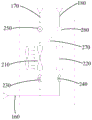
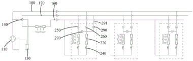
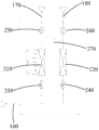
FIG. 1 is a schematic structural diagram of an air conditioner according to an embodiment of the present invention;
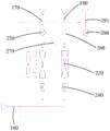
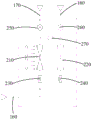
FIG. 2 is a schematic structural diagram of an air conditioner according to another embodiment of the present invention;
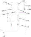
FIG. 3 is a schematic structural diagram of an air conditioner according to a next embodiment of the present invention in a cooling mode;
FIG. 4 is a schematic structural diagram of a next heating mode of the air conditioner of the present invention;
FIG. 5 is a schematic structural diagram of an air conditioner in a dehumidification and reheat mode according to an embodiment of the present invention;
FIG. 6 is a schematic structural diagram of an air conditioner according to another embodiment of the present invention;
FIG. 7 is a schematic structural diagram of an air conditioner according to still another embodiment of the present invention;
FIG. 8 is a schematic structural diagram of an air conditioner according to another embodiment of the present invention in a cooling mode;
FIG. 9 is a schematic structural diagram of an air conditioner according to another embodiment of the present invention in a cooling mode;
FIG. 10 is a schematic structural diagram of an air conditioner according to still another embodiment of the present invention in a cooling mode;
FIG. 11 is a schematic structural diagram of an air conditioner according to still another embodiment of the present invention;
FIG. 12 is a schematic structural diagram of a fifth embodiment of the air conditioner in a cooling mode according to the present invention;
FIG. 13 is a schematic structural diagram of a sixth embodiment of an air conditioner in a cooling mode according to the present invention;
FIG. 14 is a schematic structural diagram of a seventh embodiment of an air conditioner in a cooling mode according to the present invention;
FIG. 15 is a schematic structural diagram of an eighth embodiment of an air conditioner in a cooling mode according to the present invention;
FIG. 16 is a schematic structural diagram of another embodiment of the air conditioner of the present invention in the heating mode;
FIG. 17 is a schematic structural diagram of an air conditioner according to another embodiment of the present invention in a heating mode;
fig. 18 is a schematic structural view of a fourth embodiment of the air conditioner of the present invention in a heating mode;
fig. 19 is a schematic structural view of a fifth embodiment of the air conditioner of the present invention in a heating mode;
FIG. 20 is a schematic structural diagram of a sixth embodiment of the air conditioner of the present invention in a heating mode;
fig. 21 is a schematic structural view of a seventh embodiment of the air conditioner of the present invention in a heating mode;
fig. 22 is a schematic structural view of an eighth embodiment of the air conditioner in the heating mode of the present invention;
FIG. 23 is a schematic structural diagram of a ninth embodiment of the air conditioner of the present invention in a heating mode;
the reference numbers illustrate:


the implementation, functional features and advantages of the objects of the present invention will be further explained with reference to the accompanying drawings.
Detailed Description
The technical solutions in the embodiments of the present invention will be clearly and completely described below with reference to the drawings in the embodiments of the present invention, and it is obvious that the described embodiments are only a part of the embodiments of the present invention, and not all of the embodiments. All other embodiments, which can be derived by a person skilled in the art from the embodiments given herein without making any creative effort, shall fall within the protection scope of the present invention.
It should be noted that, if directional indications (such as up, down, left, right, front, and back … …) are involved in the embodiment of the present invention, the directional indications are only used to explain the relative positional relationship between the components, the movement situation, and the like in a specific posture (as shown in the drawing), and if the specific posture is changed, the directional indications are changed accordingly. In addition, the meaning of "and/or" appearing throughout is to include three juxtapositions, exemplified by "A and/or B" including either scheme A, or scheme B, or a scheme in which both A and B are satisfied.
The specific structure of the air conditioner will be mainly described below.
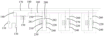
Referring to fig. 1 to 5, the whole piping structure and the component arrangement of the air conditioner will be described first; in the embodiment of the present invention, the air conditioner includes an outdoor unit 100 and an indoor unit 200, the outdoor unit 100 includes a compression mechanism 110, an outdoor heat exchanger 150 and an outdoor throttling adjustment device 120, the indoor unit 200 includes a dehumidifying heat exchanger 210, a dehumidifying throttling adjustment device 230 and a first control valve 250;
the air conditioner further includes: a discharge pipe 111 connected to a discharge side of the compression mechanism 110, a low-pressure suction pipe 113 connected to a low-pressure suction side of the compression mechanism 110, a first pipe 160 connecting the discharge pipe 111, the outdoor heat exchanger 150, the outdoor throttle control device 120, the dehumidification throttle control device 230, and the dehumidification heat exchanger 210 in this order, and a second pipe 170 connecting the dehumidification heat exchanger 210, the first control valve 250, and the low-pressure suction pipe 113 in this order, thereby forming a dehumidification circuit;
the indoor unit 200 further includes a reheat heat exchanger 220, a reheat throttle adjusting device 240, a second control valve 260, and a heat cycle device for sending heat or cold of the indoor unit 200 into the room;
the air conditioner further includes a third pipe 180 and a first branch pipe 112 branched from the discharge pipe 111, wherein the third pipe 180 forms a reheat circuit by sequentially connecting a first junction 161 of the first pipe 160, the reheat throttle control device 240, the reheat heat exchanger 220, the second control valve 260, and the first branch pipe 112, and the first junction 161 is located between the dehumidification throttle control device 230 and the outdoor throttle control device 120.
The heat circulation device may be an air supply device in some embodiments, and the dehumidifying heat exchanger 210 and the reheating heat exchanger 220 are disposed in an airflow path formed by the air supply device. Specifically, the air supply device may be a wind wheel, and the wind wheel rotates to convey air after exchanging heat with the dehumidification heat exchanger 210 and the reheat heat exchanger 220 indoors. Of course, in other embodiments, the heat cycle device may also be a water cycle device, and the dehumidification heat exchanger 210 and the reheat heat exchanger 220 send heat or cold to the indoor through the circulating water flowing in the water cycle device.
On the basis of the pipelines, the dehumidification heat exchanger 210 of the air conditioner refrigerates, and the reheating heat exchanger 220 heats, so that constant-temperature dehumidification can be realized. Wherein the dehumidification throttle adjusting device 230 comprises a dehumidification throttle valve, and the reheat throttle adjusting device 240 comprises a reheat throttle valve. Here, the dehumidification throttle and the reheat throttle may use electronic expansion valves.
The first control valve 250 and the second control valve 260 are solenoid valves or electric valves. The operation modes of cooling and dehumidifying reheating can be realized by adjusting the operation states of the first control valve 250 and the second control valve 260. Specifically, when the first control valve 250 and the second control valve 260 are opened simultaneously, the air may pass through the dehumidifying heat exchanger 210 and then the reheating heat exchanger 220, and when the dehumidifying heat exchanger 210 cools and the reheating heat exchanger 220 heats, dehumidifying and reheating can be realized; when the first control valve 250 is opened and the second control valve 260 is closed, the air passes through the dehumidifying heat exchanger 210, and cooling can be performed. So for the air conditioner can realize dehumidification reheat, also can realize refrigerating, thereby makes the function of air conditioner increase, can satisfy user's demand.
In some embodiments, the indoor unit 200 further includes a third control valve 270 and a second branch pipe 280, the second branch pipe 280 sequentially connecting a second junction 281 of the second piping 170, the third control valve 270, and a third junction 282 of the third piping 180, wherein the second junction 281 is located between the dehumidification heat exchanger 210 and the first control valve 250, and the third junction 282 is located between the reheat heat exchanger 220 and the second control valve 260.
The third control valve 270 is an electromagnetic valve or an electric valve. By adjusting the operating states of the first control valve 250, the second control valve 260 and the third electric valve 270, the air conditioner can realize multiple operating modes such as cooling, heating, dehumidification and reheating. For example, when the first control valve 250 is opened, the second control valve 260 is closed, and the third control valve 270 is opened, cooling may be performed; heating can be realized by closing the first control valve 250, opening the second control valve 260 and opening the third control valve 270; when the first control valve 250 is opened, the second control valve 260 is opened, and the third control valve 270 is closed, dehumidification and reheating can be performed.
A refrigeration mode:
referring to fig. 3, the high-temperature and high-pressure refrigerant is discharged from the discharge pipe 111, sequentially passes through the first pipe 160 and the outdoor heat exchanger 150, is throttled by the dehumidification throttle control device 230 and the reheat throttle control device 240, enters the dehumidification heat exchanger 210 and the reheat heat exchanger 220 to be cooled, finally merges and flows into the second pipe 170, and flows back into the compression mechanism 110 through the second pipe 170. During this process, the first control valve 250 is opened, the second control valve 260 is closed, and the third control valve 270 is opened.
Referring to fig. 8, the high-temperature and high-pressure refrigerant is discharged from the discharge pipe 111, sequentially passes through the first pipe 160 and the outdoor heat exchanger 150, flows into the dehumidifying heat exchanger 210 to be cooled, finally flows into the second pipe 170, and flows back into the compression mechanism 110 through the second pipe 170. This mode is a normal cooling mode in which only the dehumidifying heat exchanger 210 cools. During this process, the first control valve 250 is opened, the second control valve 260 is closed, and the third control valve 270 is closed.
Referring to fig. 9, the high-temperature and high-pressure refrigerant is discharged from the discharge pipe 111, sequentially passes through the first pipe 160 and the outdoor heat exchanger 150, flows into the reheat heat exchanger 220 to be cooled, finally flows into the second pipe 170, and flows back into the compression mechanism 110 through the second pipe 170. The mode is a normal cooling mode, and in this mode, only the reheat heat exchanger 220 cools. During this process, the first control valve 250 is open, the second control valve 260 is closed, and the third control valve 270 is open; the opening degree of the dehumidification throttle adjusting device 230 is adjusted to zero. It should be noted that, when it is not particularly emphasized that the opening degree of the throttle control device is adjusted to zero, it indicates that the throttle control device (the dehumidification throttle control device 230 or the reheat throttle control device 240) is in the open state, and the opening degree of the throttle control device can be adjusted as needed.
Referring to fig. 10, the high-temperature and high-pressure refrigerant is discharged from the discharge pipe 111, sequentially passes through the first pipe 160 and the outdoor heat exchanger 150, flows into the dehumidifying heat exchanger 210 to be cooled, finally flows into the second pipe 170, and flows back into the compression mechanism 110 through the second pipe 170. This mode is a normal cooling mode in which only the dehumidifying heat exchanger 220 cools. During this process, the first control valve 250 is open, the second control valve 260 is closed, and the third control valve 270 is open; the opening degree of the reheat throttle adjusting device 240 is adjusted to zero.
Dehumidification reheating mode:
referring to fig. 5, a high-temperature and high-pressure refrigerant is discharged from the discharge pipe 111, a part of the high-temperature and high-pressure refrigerant flows into the first pipe 160, the other part of the high-temperature and high-pressure refrigerant flows into the third pipe 180 through the first branch pipe 112, flows into the reheat heat exchanger 220 to reheat and dehumidify air, is throttled by the reheat throttle control device 240 to form a high-pressure refrigerant, and the high-pressure refrigerant is merged with the refrigerant in the first pipe 160, then flows into the dehumidification heat exchanger 210 to evaporate and dehumidify the air, finally flows into the second pipe 170, and flows back into the compression mechanism 110 through the second pipe 170. During this process, the first control valve 250 is opened, the second control valve 260 is opened, and the third control valve 270 is closed.
In some embodiments, referring to fig. 11, the indoor unit 100 further includes a fourth control valve 290 and a third branch pipe 291 branched from the second pipe 170, and the third branch pipe 291 connects the fourth control valve 290 and a third intersection 281 of the third pipe 180.
By providing the fourth control valve 290, a greater variety of possibilities are provided for the air conditioner to achieve cooling. Referring to fig. 12, a high-temperature and high-pressure refrigerant is discharged from the discharge pipe 111, sequentially passes through the first pipe 160 and the outdoor heat exchanger 150, is throttled by the dehumidification throttle control device 230 and the reheat throttle control device 240, enters the dehumidification heat exchanger 210 and the reheat heat exchanger 220 to be cooled, finally merges and flows into the third branch pipe 291, flows back to the second pipe 170 through the third branch pipe 291, and further flows back into the compression mechanism 110. During this process, the first control valve 250 is closed, the second control valve 260 is closed, the third control valve 270 is opened, and the fourth control valve 290 is opened.
Referring to fig. 13, the high-temperature and high-pressure refrigerant is discharged from the discharge pipe 111, sequentially passes through the first pipe 160 and the outdoor heat exchanger 150, then a part of the refrigerant passes through the dehumidification throttle control device 230 and enters the dehumidification heat exchanger 210 to be cooled, and the other part of the refrigerant passes through the reheat throttle control device 240 and enters the reheat heat exchanger 220 to be cooled, and finally, the refrigerant is converged and flows into the second pipe 170 and flows back into the compression mechanism 110 through the second pipe 170. In this process, the first control valve 250 is opened, the second control valve 260 is closed, the third control valve 270 is closed, and the fourth control valve 290 is opened.
Referring to fig. 14, the high-temperature and high-pressure refrigerant is discharged from the discharge pipe 111, sequentially passes through the first pipe 160 and the outdoor heat exchanger 150, then passes through the reheat throttle adjusting device 240, enters the reheat heat exchanger 220 to be cooled, finally flows into the third branch pipe 291, flows back to the second pipe 170 through the third branch pipe 291, and further flows back into the compression mechanism 110. In this process, the first control valve 250 is closed, the second control valve 260 is closed, the third control valve 270 is opened, the fourth control valve 290 is opened, and the opening degree of the dehumidification throttle adjustment device 230 is adjusted to zero.
Referring to fig. 15, the high-temperature and high-pressure refrigerant is discharged from the discharge pipe 111, sequentially passes through the first pipe 160 and the outdoor heat exchanger 150, then passes through the dehumidification throttle adjustment device 230, enters the dehumidification heat exchanger 210 to perform cooling, finally flows into the third branch pipe 291, flows back to the second pipe 160 through the third branch pipe 291, and further flows back into the compression mechanism 110. In this process, the first control valve 250 is closed, the second control valve 260 is closed, the third control valve 270 is opened, the fourth control valve 290 is opened, and the opening degree of the reheat throttle adjusting device 240 is adjusted to zero.
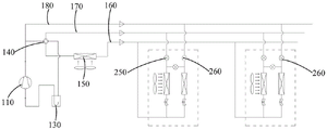
In some embodiments, referring to fig. 2, the outdoor unit 100 further includes a reversing device 140, the reversing device 140 has a first switching state and a second switching state,
in the first switching state, the switching device 140 causes the discharge pipe 111 to communicate with the first pipe 160 and causes the low-pressure suction pipe 113 to communicate with the second pipe 170;
in the second switching state, the switching device 140 causes the discharge pipe 111 to communicate with the second pipe 170 and causes the low-pressure suction pipe 113 to communicate with the first pipe 160.
The flow path of the refrigerant can be changed by arranging the reversing device 140, so that the working mode of the air conditioner can be changed. In the first switching state, the high-temperature and high-pressure refrigerant is discharged from the discharge pipe 111, a part of the refrigerant flows into the first pipe 160, the other part of the refrigerant flows into the third pipe 180 through the first branch pipe 112, and finally flows back into the compression mechanism 110 from the second pipe 170; in the first switching state, the air conditioner can realize refrigeration and dehumidification reheating. In the second switching state, the high-temperature and high-pressure refrigerant is discharged from the discharge pipe 111, a part of the refrigerant flows into the second pipe 170, the other part of the refrigerant flows into the third pipe 180 through the first branch pipe 112, and finally flows back into the compression mechanism 110 from the first pipe 160; in the second switching state, the air conditioner can realize heating.
Of course, in other embodiments, the indoor unit 200 further includes a third control valve 270 and a second branch pipe 280, the second branch pipe 280 connects a second intersection 281 of the second piping 170, the third control valve 270, and a third intersection 282 of the third piping 180 in sequence, wherein the second intersection 281 is located between the dehumidification heat exchanger 210 and the first control valve 250, and the third intersection 282 is located between the reheat heat exchanger 220 and the second control valve 260;
the outdoor unit 100 further includes a direction changing device 140, the direction changing device 140 having a first switching state in which the direction changing device 140 causes the discharge pipe 111 to communicate with the first pipe 160 and causes the low pressure suction pipe 113 to communicate with the second pipe 170; in the second switching state, the switching device 140 causes the discharge pipe 111 to communicate with the second pipe 170 and causes the low-pressure suction pipe 113 to communicate with the first pipe 160.
It should be noted that, by the arrangement of the reversing device 140, the first control valve 250, the second control valve 260 and the third control valve 270, not only the flow path of the refrigerant in the air conditioner can be changed, but also the air conditioner can realize various modes such as cooling, heating, dehumidifying and reheating, etc. Several modes of operation of the air conditioner will be described in detail below with reference to specific embodiments.
A refrigeration mode:
referring to fig. 2 and 3, the reversing device 140 is adjusted to a first switching state; the first control valve 250 is opened, the second control valve 260 is closed, and the third control valve 270 is opened. Here, the high-temperature and high-pressure refrigerant is discharged from the discharge pipe 111, sequentially passes through the first pipe 160 and the outdoor heat exchanger 150, throttled by the dehumidification throttle control device 230 and the reheat throttle control device 240, respectively, and then flows into the heat exchangers connected in series, respectively, to perform cooling, and finally, the two portions of the refrigerant join together and flow into the second pipe 170, and then flows back into the compression mechanism 110 through the second pipe 170. This mode is a forced cooling mode in which both the dehumidifying heat exchanger 210 and the reheating heat exchanger 220 cool.
Referring to fig. 8, the reversing device 140 is adjusted to the first switching state; the first control valve 250 is opened, the second control valve 260 is closed, and the third control valve 270 is closed. Here, the high-temperature and high-pressure refrigerant is discharged from the discharge pipe 111, sequentially passes through the first pipe 160 and the outdoor heat exchanger 150, flows into the dehumidifying heat exchanger 210 to be cooled, finally flows into the second pipe 170, and flows back into the compression mechanism 110 through the second pipe 170. This mode is a normal cooling mode in which only the dehumidifying heat exchanger 210 cools.
Referring to fig. 9, the reversing device 140 is adjusted to the first switching state; opening the first control valve 250, closing the second control valve 260, and opening the third control valve 270; the opening degree of the dehumidification throttle adjusting device 230 is adjusted to zero. Here, the high-temperature and high-pressure refrigerant is discharged from the discharge pipe 111, sequentially passes through the first pipe 160 and the outdoor heat exchanger 150, flows into the reheat heat exchanger 220 to be cooled, finally flows into the second pipe 170, and flows back into the compression mechanism 110 through the second pipe 170. The mode is a normal cooling mode, and in this mode, only the reheat heat exchanger 220 cools.
Referring to fig. 10, the reversing device 140 is adjusted to a first switching state; opening the first control valve 250, closing the second control valve 260, and opening the third control valve 270; the opening degree of the reheat throttle adjusting device 240 is adjusted to zero. Here, the high-temperature and high-pressure refrigerant is discharged from the discharge pipe 111, sequentially passes through the first pipe 160 and the outdoor heat exchanger 150, flows into the dehumidifying heat exchanger 210 to be cooled, finally flows into the second pipe 170, and flows back into the compression mechanism 110 through the second pipe 170. This mode is a normal cooling mode in which only the dehumidifying heat exchanger 220 cools.
Heating mode:
referring to fig. 4, the commutation device 140 is adjusted to a second switching state; the first control valve 250 is closed, the second control valve 260 is opened, and the third control valve 270 is opened; here, the high-temperature and high-pressure refrigerant is discharged from the discharge pipe 111, flows into the third pipe 180 through the first branch pipe 112, flows into the reheat heat exchanger 220 and the dehumidification heat exchanger 210, heats the refrigerant, and finally joins the two portions of the refrigerant, flows into the first pipe 160, and flows back into the compression mechanism 110 through the first pipe 160. This mode is a forced heat mode in which both the dehumidification heat exchanger 210 and the reheat heat exchanger 220 generate heat.
Referring to fig. 16, the commutation device 140 is adjusted to a second switching state; opening the first control valve 250, closing the second control valve 260, and opening the third control valve 270; here, the high-temperature and high-pressure refrigerant is discharged from the discharge pipe 111, flows into the dehumidifying heat exchanger 210 and the reheating heat exchanger 220 through the second pipe 170, heats the refrigerant, joins the two last-part refrigerant, flows into the first pipe 160, and flows back into the compression mechanism 110 through the first pipe 160. This mode is a forced heat mode in which both the dehumidification heat exchanger 210 and the reheat heat exchanger 220 generate heat.
Referring to fig. 17, the reversing device 140 is adjusted to the second switching state; opening the first control valve 250, the second control valve 260, and the third control valve 270; here, the high-temperature and high-pressure refrigerant is discharged from the discharge pipe 111, and a part of the refrigerant flows into the third pipe 180 through the first branch pipe 112 and flows into the reheat heat exchanger 220 to perform heating; the other part flows into the dehumidifying heat exchanger 210 through the second pipe 170 to perform heating, and the last two parts join together and flow into the first pipe 160, and flow back into the compression mechanism 110 through the first pipe 160. This mode is a forced heat mode in which both the dehumidification heat exchanger 210 and the reheat heat exchanger 220 generate heat.
Referring to fig. 18, the commutation device 140 is adjusted to a second switching state; opening the first control valve 250, closing the second control valve 260, and closing the third control valve 270; here, the high-temperature and high-pressure refrigerant is discharged from the discharge pipe 111, flows into the dehumidifying heat exchanger 210 through the second pipe 170, heats, finally flows into the first pipe 160, and flows back into the compression mechanism 110 through the first pipe 160. This mode is a normal heating mode in which heat is generated by the dehumidifying heat exchanger 210.
Referring to fig. 19, the reversing device 140 is adjusted to the second switching state; the first control valve 250 is closed, the second control valve 260 is opened, and the third control valve 270 is closed. Here, the high-temperature and high-pressure refrigerant is discharged from the discharge pipe 111, flows into the third pipe 180 through the first branch pipe 112, flows into the reheat heat exchanger 220 to be heated, finally flows into the first pipe 160, and flows back into the compression mechanism 110 through the first pipe 160. This mode is a normal heating mode, and in this mode, only the reheat heat exchanger 220 heats.
Referring to fig. 20, the commutation device 140 is adjusted to a second switching state; opening the first control valve 250, closing the second control valve 260, and opening the third control valve 270; the opening degree of the dehumidification throttle adjustment device 230 is adjusted to zero. Here, the high-temperature and high-pressure refrigerant is discharged from the discharge pipe 111, flows into the reheat heat exchanger 220 through the second pipe 170 to be heated, finally flows into the first pipe 160, and flows back into the compression mechanism 110 through the first pipe 160. This mode is a normal heating mode, and in this mode, only the reheat heat exchanger 220 heats.
Referring to fig. 21, the reversing device 140 is adjusted to a second switching state; opening the first control valve 250, closing the second control valve 260, and opening the third control valve 270; the opening degree of the reheat throttle adjusting device 240 is adjusted to zero. Here, the high-temperature and high-pressure refrigerant is discharged from the discharge pipe 111, flows into the reheat heat exchanger 220 through the second pipe 170 to be heated, finally flows into the first pipe 160, and flows back into the compression mechanism 110 through the first pipe 160. This mode is a normal heating mode, and in this mode, only the reheat heat exchanger 220 heats.
Referring to fig. 22, the reversing device 140 is adjusted to the second switching state; opening the first control valve 250, opening the second control valve 260, and closing the third control valve 270; the opening degree of the reheat throttle adjusting device 240 is adjusted to zero. At this time, the high-temperature and high-pressure refrigerant is discharged from the discharge pipe 111, flows into the dehumidifying heat exchanger 210 through the second pipe 170, heats, finally flows into the first pipe 160, and flows back into the compression mechanism 110 through the first pipe 160. This mode is a normal heating mode in which only the dehumidifying heat exchanger 210 heats.
Referring to fig. 23, the reversing device 140 is adjusted to the second switching state; opening the first control valve 250, opening the second control valve 260, and closing the third control valve 270; the opening degree of the dehumidification throttle adjustment device 230 is adjusted to zero. At this time, the high-temperature and high-pressure refrigerant is discharged from the discharge pipe 111, flows into the third pipe 180 through the first branch pipe 112, flows into the reheat heat exchanger 220 to be heated, finally flows into the first pipe 160, and flows back into the compression mechanism 110 through the first pipe 160. This mode is a normal heating mode, and in this mode, only the reheat heat exchanger 220 heats.
Dehumidification reheating mode:
referring to fig. 5, the reversing device 140 is adjusted to a first switching state; the first control valve 250 is opened, the second control valve 260 is opened, and the third control valve 270 is closed. At this time, the high-temperature and high-pressure refrigerant is discharged from the discharge pipe 111, a part of the high-temperature and high-pressure refrigerant flows into the first pipe 160, the other part of the high-temperature and high-pressure refrigerant flows into the third pipe 180 through the first branch pipe 112, flows into the reheat heat exchanger 220 to reheat and dehumidify the air, is throttled by the reheat throttle control device 240 to form a high-pressure refrigerant, and the high-pressure refrigerant joins the refrigerant in the first pipe 160, flows into the dehumidification heat exchanger 210 to evaporate and dehumidify the air, finally flows into the second pipe 170, and flows back into the compression mechanism 110 through the second pipe 170.
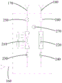
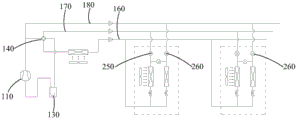
In some embodiments, referring to fig. 1, 2, 6 and 7, the air conditioner includes a plurality of indoor units 200, for example, two, three or more indoor units 200, and the heat exchanger types included in the indoor units 200 may be different, such as one or more of an indoor unit with a constant temperature dehumidification function (including both the dehumidification heat exchanger 210 and the reheat heat exchanger 220, a normal cooling/heating indoor unit (including only one heat exchanger and a corresponding throttle adjusting device), and an indoor unit with a reversing device 140 capable of freely switching a cooling state or a heating state, so that the air conditioner may perform a hybrid operation of cooling, heating, dehumidification and reheating, etc.
Specifically, the air conditioner further includes a first connection pipe 310 (shown in fig. 1) branched from a fourth intersection 311 of the first pipe 160, a second connection pipe 320 (shown in fig. 2) branched from the second pipe 170, and a third connection pipe 330 (shown in fig. 3) branched from the third pipe 180, the fourth intersection 311 being located between the dehumidification throttle adjusting device 230 and the outdoor heat exchanger 150; the air conditioner further includes a plurality of indoor units 200, and the plurality of indoor units 200 are connected in parallel to the first connection pipe 310, the second connection pipe 320, and the third connection pipe 330.
The plurality of indoor units can be used for cooling completely, or dehumidifying and reheating completely, or one part of indoor units can be used for cooling, and the other part of indoor units can be used for dehumidifying and reheating.
For example, referring to fig. 6, the air conditioner includes a first indoor unit and a second indoor unit, and both the first indoor unit and the second indoor unit may heat, dehumidify and reheat, or both the first indoor unit and the second indoor unit may cool, and the second indoor unit may dehumidify and reheat.
Specifically, referring to fig. 6, the reversing device 140 is switched to the first switching state, the high-temperature and high-pressure refrigerant is discharged from the discharge pipe 111, a portion of the high-temperature and high-pressure refrigerant flows into the first pipe 160, another portion of the high-temperature and high-pressure refrigerant flows into the third pipe 180 through the first branch pipe 112, and after the refrigerant flows through the indoor unit 200 and completes its operation, the refrigerant flows back into the compression mechanism 110 through the second pipe 170. Wherein, the first control valve 250 of the first indoor unit is opened, the second control valve 260 is closed, the third control valve 270 is opened, and the first indoor unit can realize refrigeration; when the first control valve 250, the second control valve 260, and the third control valve 270 of the second indoor unit are opened and closed, the second indoor unit can perform dehumidification and reheating.
It should be noted that, when the reversing device 140 is switched to the first switching state, at least two indoor units 200 of the plurality of indoor units 200 need to be simultaneously turned on in order to recover waste heat, and at least one indoor unit 200 of the turned-on at least two indoor units 200 performs cooling or dehumidification reheating. That is, at least two indoor units 200 that are turned on cannot simultaneously heat. At this time, the high-temperature and high-pressure refrigerant is discharged from the discharge pipe 111, a small portion of the refrigerant flows into the first pipe 160 to maintain the system balance, and the other portion of the refrigerant flows into the third pipe 180 through the first branch pipe 112; the heating indoor unit 200 receives the refrigerant from the third pipe 180, and the high-pressure liquid refrigerant formed by heating enters the first pipe 160, and then enters the cooling or dehumidifying and reheating indoor unit 200, and after being evaporated, cooled or dehumidified in the cooling or dehumidifying and reheating indoor unit 200, the refrigerant flows back to the compression mechanism 110 through the second pipe 170. Therefore, waste heat discharged into the atmosphere can be reduced, and waste heat utilization is realized, so that the energy consumption ratio is improved, and energy conservation and environmental protection are realized.
Of course, when the switching device 140 is switched to the second switching state, all of the indoor units can be heated. For example, referring to fig. 7, the reversing device 140 is switched to the second switching state, the high-temperature and high-pressure refrigerant is discharged from the discharge pipe 111, a portion of the refrigerant flows into the second pipe 170, another portion of the refrigerant flows into the third pipe 180 through the first branch pipe 112, and after the refrigerant flows through the indoor unit 200 and is completely operated, the refrigerant flows back into the compression mechanism 110 through the first pipe 160. Wherein the first control valve 250 of the first indoor unit is closed, the second control valve 260 is opened, and the third control valve 270 is opened; the first control valve 250 of the second indoor unit is opened, the second control valve 260 is opened, and the third control valve 270 is closed; but is not limited thereto.
It is worth mentioning that the air conditioner can also realize the combination of three modes of refrigeration, heating and dehumidification reheating. For example, referring to fig. 2, the air conditioner includes a first indoor unit, a second indoor unit, and a third indoor unit, wherein the first indoor unit cools, the second indoor unit heats, and the third indoor unit dehumidifies and reheats. Specifically, the commutation device 140 switches to a first switching state; the first control valve 250 of the first indoor unit is opened, the second control valve 260 is closed, and the third control valve 270 is opened (as shown in fig. 3); the first control valve 250 of the second indoor unit is closed, the second control valve 260 is opened, and the third control valve 270 is opened (as shown in fig. 4); the first control valve 250 of the third indoor unit is opened, the second control valve 260 is opened, and the third control valve 270 is closed (as shown in fig. 5). In this embodiment, the refrigerant flowing out of the second room unit for heating must flow into the first room unit for cooling or the third room unit for dehumidification and reheating to exchange heat, and then flow back to the second pipe 170 and flow back to the compression mechanism 110 through the second pipe 170.
In some embodiments, to improve the ability of the air conditioner to heat at low temperatures, the air conditioner further comprises an economizer 190; the economizer 190 is provided in the first pipe 160 between the outdoor heat exchanger 150 and the first cross point 161, and a return pipe of the economizer 190 communicates with the medium-pressure suction port of the compression mechanism 110. The return pipe may have various forms, and the return pipe may include only a return pipe body, or may include a return pipe body and a first communication pipe, one end of the first communication pipe being communicated with the return pipe body, and the other end being communicated with the suction port of the compressor. The compression mechanism 110 in this case is a vapor-injection enthalpy compressor, and has a low-pressure suction port and an intermediate-pressure suction port.
The economizer 190 has a throttling function, a first refrigerant flow path and a second refrigerant flow path are arranged in the economizer 190, and two ends of the first refrigerant flow path are respectively communicated with the first piping 160 at two ends of the economizer 190; one end of the second refrigerant flow path is communicated with the first piping 160 through a liquid taking pipe 192, and the other end is communicated with the medium pressure suction port of the compressor through a return pipe; the liquid extraction pipe 192 is provided with a liquid extraction throttle valve 191. One end of the first refrigerant fluid is communicated with a refrigerant inlet of the economizer 190, and the other end is communicated with a refrigerant outlet of the economizer 190. The liquid-taking pipe 192 has one end communicating with the first pipe 160 and the other end communicating with the second refrigerant passage, and has one end communicating with the medium-pressure suction port of the compressor and the other end communicating with the second refrigerant passage.
Thus, the compressor discharge air respectively enters the reheating heat exchanger 220 and the dehumidifying heat exchanger 210 for heating, and the liquid refrigerant coming out of the reheating heat exchanger 220 and the dehumidifying heat exchanger 210 enters the economizer 190 and then is divided into two parts: the first part directly enters the outdoor heat exchanger 150 to evaporate and absorb heat after being throttled and reduced in pressure by the outdoor throttling adjusting device 120 (electronic expansion valve), the second part enters the economizer 190 to absorb heat and evaporate after being throttled and reduced in pressure by the liquid taking throttle valve 191 (electronic expansion valve), the evaporated medium-pressure saturated steam enters the medium-pressure air suction port of the compressor through the return pipe and is compressed together with the refrigerant of the low-pressure air suction port of the compressor after being mixed with the refrigerant, the problems of small refrigerant flow, low return air pressure, high compression ratio and the like in a low-temperature environment are solved, and the reliability of the low-temperature heating quantity and the system is improved. By the technology, when the outdoor environment temperature is low, the refrigerant suction amount of the compressor in the low-temperature environment is increased through the system design of the enhanced vapor injection compressor and the economizer 190, so that the low-temperature heating capacity is improved, the compression ratio in the low-temperature environment is reduced, and the reliability of the system can be improved.
In other embodiments, in order to avoid the unpleasant noise generated when the refrigerant in the vapor-liquid two-phase state passes through the indoor throttling device, the air conditioner further includes a gas-liquid separator 130 and an economizer 190, wherein the gas-liquid separator 130 is disposed on the low-pressure suction pipe 113; the economizer 190 is provided in the first pipe 160 between the outdoor heat exchanger 150 and the first cross point 161, and a return pipe of the economizer 190 communicates with the gas-liquid separator 130. The return pipe may have various forms, and the return pipe may include only a return pipe body, or may include a return pipe body and a second communication pipe, one end of the second communication pipe is communicated with the return pipe body, and the other end is communicated with the gas-liquid separator 130.
In order to facilitate control, in some examples, a control valve is arranged on the return pipe or a communication pipe between the return pipe and a medium-pressure suction inlet of the compressor; the return pipe is communicated with the gas-liquid separator 130 through a low pressure suction pipe 113, and a control valve is provided on the return pipe or a connection pipe between the return pipe and the low pressure suction pipe 113.
The invention further reduces the condensation temperature of the refrigerant at the outlet of the outdoor heat exchanger 150 and improves the supercooling degree by controlling the liquid taking throttle valve 191 (electronic expansion valve) in the system design loop of the economizer 190 through adopting the system design with the economizer 190 on the basis of the three-pipe dehumidification reheating scheme, so that the refrigerant is completely condensed into liquid, the liquid refrigerant enters the indoor heat exchanger to absorb heat and evaporate after being throttled and decompressed by the indoor electronic expansion valve, and when the refrigerant passing through the indoor throttling device is in a full liquid state, the abnormal sound of the refrigerant generated in a gas-liquid two-phase state can be solved.
The high-pressure high-temperature gaseous refrigerant enters the outdoor heat exchanger 150 for condensation and heat exchange, and the gas-liquid two-phase medium-temperature high-pressure refrigerant coming out of the outdoor heat exchanger 150 enters the economizer 190 and then is divided into two parts: the first part is throttled and depressurized by a liquid taking throttle valve 191, then enters an economizer 190 through a liquid taking pipe 192 to absorb heat and evaporate, the evaporated gaseous refrigerant enters a gas-liquid separator 130 through a return pipe, a control valve (solenoid valve) and a connecting pipe, then is mixed with the gaseous refrigerant which is subjected to heat absorption and evaporation by an indoor heat exchanger, and then enters a compressor air suction port, the second part is further condensed and heat exchanged from the economizer 190, the gas-liquid two-phase refrigerant is changed into a pure liquid refrigerant, the pure liquid refrigerant flows indoors, and is throttled and depressurized by a dehumidification throttle valve and a reheating throttle valve and then respectively enters a dehumidification heat exchanger 210 and a reheating heat exchanger 220 to absorb heat and evaporate. The refrigerant entering the dehumidification regulating valve and the reheating regulating valve (electronic expansion valve) is changed into pure liquid from gas-liquid two-phase state, so that the problem of refrigerant abnormal sound generated when the gas-liquid two-phase refrigerant passes through the throttling device is solved.
In some embodiments, the air conditioner is also used to supply water to floor heating or to prepare domestic water for people.
When the air conditioner further comprises a floor heating module, the air conditioner further comprises a heat exchange water tank and a floor heating water flow pipe communicated with the heat exchange water tank; a floor heating heat exchanger is arranged in the heat exchange water tank, a refrigerant inlet of the floor heating heat exchanger is communicated with a third piping 180, a refrigerant outlet of the floor heating heat exchanger is communicated with the first piping 160, and a fifth control valve is arranged on the second piping 170.
Specifically, in this embodiment, ground heating water pipe can bury underground in the middle of ground or the wall, ground heating water pipe and heat exchange water tank intercommunication, and water among the heat exchange water tank can be at ground heating water pipe mesocycle for the temperature in the ground heating water pipe is equivalent with the temperature in the heat exchange water tank. When a high-temperature and high-pressure refrigerant passes through the floor heating heat exchanger, the floor heating heat exchanger exchanges heat with water in a heat exchange water tank to heat cold water in the water tank; when low-pressure refrigerant passes through the floor heating heat exchanger, the floor heating heat exchanger exchanges heat with water in the heat exchange water tank to cool the water in the heat exchange water tank. When the ground heating heat exchanger is in operation, the fifth control valve can be selectively closed (when the ground heating is required to be efficiently heated, the fifth control valve is closed), and at the moment, the outdoor unit 100 mainly serves the ground heating heat exchanger so as to improve the heat exchange efficiency of the ground heating heat exchanger.
In some other embodiments, the air conditioner further comprises: a first connection pipe 310 branched from a fourth intersection 311 of the first pipe 160, and a second connection pipe 320 branched from the second pipe 170, the fourth intersection 311 being located between the dehumidification throttle control device 230 and the outdoor heat exchanger 150; the air conditioner further includes a water treatment device including a water heat exchanger for heating or cooling water in the water container and a water container, the water heat exchanger being connected in parallel with the indoor unit 200 on the first connection pipe 310 and the second connection pipe 320. The water heat exchanger heats or refrigerates water in the water container, of course, the water containers can be multiple, and the water heat exchangers can also be multiple and arranged in parallel, so that one water container can contain hot water, and the other water container can contain cold water, and the cold water and the hot water can be supplied simultaneously. When hot water is required to be produced, high-temperature refrigerants pass through the water heat exchanger, so that heat energy is transferred to water in the container; when the refrigeration water is needed, the low-temperature refrigerant passes through the water heat exchanger, so that the cold energy is transferred to the water in the container.
In some embodiments, the indoor unit further comprises electrically-assisted heat. Wherein the electrically-assisted heat is located between the dehumidifying heat exchanger 210 and the reheating heat exchanger 220; alternatively, the electric auxiliary heat is located at the side of the dehumidification heat exchanger 210 away from the reheat heat exchanger 220; alternatively, the electric auxiliary heat is located at the side of the reheating heat exchanger 220 away from the dehumidifying heat exchanger 210. Here, the specific location of the electric auxiliary heat is not limited. The auxiliary heating is carried out by arranging the electric auxiliary heat, so that the indoor temperature is not too low, and the use comfort of the air conditioner is improved. For example, when the dehumidification heat exchanger 210 or the reheating heat exchanger 220 is separately opened, the indoor temperature is low, and auxiliary heating can be performed through electric auxiliary heating at the moment, so that the indoor temperature is rapidly increased, and the experience comfort of a user is improved.
Aiming at the air conditioner, the invention also provides a control method of the air conditioner, which comprises the following steps:
s10, acquiring a mode instruction;
specifically, in this embodiment, there are various modes for acquiring the mode instruction, and the mode instruction may be acquired from an external terminal, such as a mobile phone, a remote controller, and the like; can also be obtained from other household electrical appliance equipment, such as an electric fan, an air purifier and the like; the calculation can also be carried out by detecting the self operating parameters or detecting the external environmental parameters, such as the indoor temperature; of course, the information can also be acquired from the cloud. The mode commands may include cooling, heating, dehumidification reheat, defrosting and non-sensible defrosting, user demand (e.g., temperature 15℃.), and the like.
S20, adjusting the working state of the first control valve 250 and the second control valve 260 according to the mode command. According to different mode instructions, the working states of the first control valve 250 and the second control valve 260 are adjusted, for example, during refrigeration, the first control valve 250 is opened, and the second control valve 260 is closed, so that refrigeration can be realized when air passes through the dehumidifying heat exchanger 210; when dehumidification is reheated, open first control valve 250 and second control valve 260, so, the air can pass through dehumidification heat exchanger 210 earlier and pass through reheat heat exchanger 220 again, when dehumidification heat exchanger 210 refrigerates, reheat heat exchanger 220 heats, can realize dehumidification and reheat.
In this embodiment, the operating states of the first control valve 250 and the second control valve 260 are adjusted, so that the air conditioner can realize dehumidification and reheating, and also can realize refrigeration, thereby increasing the functions of the air conditioner and meeting the requirements of users.
For example, the mode command may include a cooling mode command, and the step of adjusting the operation states of the first and second control valves 250 and 260 according to the mode command may include:
the first control valve 250 is opened and the second control valve 260 is closed according to the cooling mode command.
Specifically, when the first control valve 250 is opened and the second control valve 260 is closed, the air passes through the dehumidifying heat exchanger 210, and cooling can be performed.
For another example, the mode command includes a dehumidification and reheat mode command, and the step of adjusting the operation states of the first control valve 250 and the second control valve 260 according to the mode command includes:
the first control valve 250 is opened and the second control valve 260 is opened according to the dehumidification reheat mode command.
Specifically, when the first control valve 250 and the second control valve 260 are simultaneously opened, the air may pass through the dehumidifying heat exchanger 210 and then the reheating heat exchanger 220, and when the dehumidifying heat exchanger 210 cools and the reheating heat exchanger 220 heats, dehumidifying and reheating may be performed.
It should be noted that, not generally, the control method of the air conditioner further includes adjusting the opening degrees of the dehumidification throttle control device 230 and the reheat throttle control device 240 according to the mode command. For example, the opening degrees of the dehumidification throttle control device 230 and the reheat throttle control device 240 are adjusted to be larger or smaller according to the mode command.
In some embodiments, the step of obtaining the mode instruction is further followed by:
s30, adjusting the operating state of the third control valve 270 according to the mode command.
The indoor unit 200 further includes a third control valve 270 and a second branch pipe 280, and the second branch pipe 280 sequentially connects a second intersection 281 of the second pipe 170, the third control valve 270, and a third intersection 282 of the third pipe 180, wherein the second intersection 281 is located between the dehumidification heat exchanger 210 and the first control valve 250, and the third intersection 282 is located between the reheat heat exchanger 220 and the second control valve 260.
The sequence of the step of adjusting the working state of the third control valve 270 according to the mode instruction and the step of adjusting the working states of the first control valve 250 and the second control valve 260 according to the mode instruction is not limited. That is, the order of adjusting the first control valve 250, the second control valve 260, and the third control valve 270 according to the mode command is not limited.
By adjusting the operating states of the first control valve 250, the second control valve 260 and the third electric valve 270, the air conditioner can realize multiple operating modes such as cooling, heating, dehumidification and reheating. For example, when the first control valve 250 is opened, the second control valve 260 is closed, and the third control valve 270 is opened, cooling may be performed; heating can be realized by closing the first control valve 250, opening the second control valve 260 and opening the third control valve 270; when the first control valve 250 is opened, the second control valve 260 is opened, and the third control valve 270 is closed, dehumidification and reheating can be performed.
The following is a description of the requirements of the different operating modes:
the mode command includes a cooling mode command, and the step of adjusting the operation states of the first, second, and third control valves 250, 260, and 270 according to the mode command includes:
opening the first control valve 250, closing the second control valve 260, and opening the third control valve 270 (as shown in fig. 3) according to the cooling mode command;
in this mode, the high-temperature and high-pressure refrigerant is discharged from the discharge pipe 111, sequentially passes through the first pipe 160 and the outdoor heat exchanger 150, is throttled by the dehumidification throttle control device 230 and the reheat throttle control device 240, enters the dehumidification heat exchanger 210 and the reheat heat exchanger 220 to be cooled, finally merges and flows into the second pipe 170, and flows back into the compression mechanism 110 through the second pipe 170. The cooling mode is a strong cooling mode, and in this mode, both the dehumidifying heat exchanger 210 and the reheating heat exchanger 220 cool.
Alternatively, the first control valve 250 is opened, the second control valve 260 is closed, and the third control valve 270 is closed according to the cooling mode command (as shown in fig. 8);
in this mode, the high-temperature and high-pressure refrigerant is discharged from the discharge pipe 111, sequentially passes through the first pipe 160, the outdoor heat exchanger 150, and the dehumidification throttle control device 230, enters the dehumidification heat exchanger 210 to perform cooling, finally flows into the second pipe 170, and flows back into the compression mechanism 110 through the second pipe 170. This cooling mode is a normal cooling mode in which only the dehumidifying heat exchanger 210 cools.
Or, according to the cooling mode command, the first control valve 250 is opened, the second control valve 260 is closed, and the third control valve 270 is opened; the opening degree of the dehumidification throttle adjusting device 230 is adjusted to zero (as shown in fig. 9);
in this mode, the high-temperature and high-pressure refrigerant is discharged from the discharge pipe 111, sequentially passes through the first pipe 160 and the outdoor heat exchanger 150, flows into the reheat heat exchanger 220 to be cooled, finally flows into the second pipe 170, and flows back into the compression mechanism 110 through the second pipe 170. The mode is a normal cooling mode, and in this mode, only the reheat heat exchanger 220 cools.
Alternatively, the first control valve 250 is opened, the second control valve 260 is closed, and the third control valve 270 is opened according to the cooling mode command; the opening degree of the reheat throttle adjusting device 240 is adjusted to zero (as shown in fig. 10).
In this mode, the high-temperature and high-pressure refrigerant is discharged from the discharge pipe 111, sequentially passes through the first pipe 160 and the outdoor heat exchanger 150, flows into the dehumidifying heat exchanger 210 to be cooled, finally flows into the second pipe 170, and flows back into the compression mechanism 110 through the second pipe 170. This mode is a normal cooling mode in which only the dehumidifying heat exchanger 220 cools.
The mode command includes a dehumidification and reheat mode command, and the step of adjusting the operation states of the first, second, and third control valves 250, 260, and 270 according to the mode command includes:
according to the dehumidification and reheat mode command, the first control valve 250 is opened, the second control valve 260 is opened, and the third control valve 270 is closed (as shown in fig. 5).
In this mode, the high-temperature and high-pressure refrigerant is discharged from the discharge pipe 111, a part of the high-temperature and high-pressure refrigerant flows into the first pipe 160, the other part of the high-temperature and high-pressure refrigerant flows into the third pipe 180 through the first branch pipe 112, flows into the reheat heat exchanger 220 to reheat and dehumidify the air, is throttled by the reheat throttle control device 240 to form a high-pressure refrigerant, and the high-pressure refrigerant joins the refrigerant in the first pipe 160, flows into the dehumidification heat exchanger 210 to evaporate and dehumidify the air, finally flows into the second pipe 170, and flows back into the compression mechanism 110 through the second pipe 170.
In some embodiments, the step of obtaining the mode instruction further comprises:
and S40, adjusting the working state of the reversing device 140 according to the mode command.
The outdoor unit 100 further includes a direction changing device 140, the direction changing device 140 having a first switching state in which the direction changing device 140 causes the discharge pipe 111 to communicate with the first pipe 160 and causes the low pressure suction pipe 113 to communicate with the second pipe 170; in the second switching state, the switching device 140 causes the discharge pipe 111 to communicate with the second pipe 170 and causes the low-pressure suction pipe 113 to communicate with the first pipe 160.
The sequence of the step of adjusting the working state of the reversing device 140 according to the mode instruction and the step of adjusting the working states of the first control valve 250 and the second control valve 260 according to the mode instruction is not limited. That is, the order of adjusting the first control valve 250, the second control valve 260, and the direction switching device 140 according to the mode command is not limited.
The flow path of the refrigerant can be changed by arranging the reversing device 140, so that the working mode of the air conditioner can be changed. In the first switching state, the high-temperature and high-pressure refrigerant is discharged from the discharge pipe 111, a part of the refrigerant flows into the first pipe 160, the other part of the refrigerant flows into the third pipe 180 through the first branch pipe 112, and finally flows back into the compression mechanism 110 from the second pipe 170; in the first switching state, the air conditioner can realize refrigeration and dehumidification reheating. In the second switching state, the high-temperature and high-pressure refrigerant is discharged from the discharge pipe 111, a part of the refrigerant flows into the second pipe 170, the other part of the refrigerant flows into the third pipe 180 through the first branch pipe 112, and finally flows back into the compression mechanism 110 from the first pipe 160; in the second switching state, the air conditioner can realize heating.
The following is a description of the requirements of the different operating modes:
the mode command includes a cooling mode command, and the step of adjusting the operation states of the first control valve 250, the second control valve 260, and the direction changing device 140 according to the mode command includes:
the direction switching device 140 is adjusted to the first switching state according to the cooling mode command, the first control valve 250 is opened, and the second control valve 260 is closed.
In this mode, the high-temperature and high-pressure refrigerant is discharged from the discharge pipe 111, flows into the dehumidifying heat exchanger 210 through the first pipe 160 to be cooled, and flows back into the compression mechanism 110 through the second pipe 170.
The mode command includes a heating mode command, and the step of adjusting the operating states of the first control valve 250, the second control valve 260, and the direction changing device 140 according to the mode command includes:
adjusting the reversing device 140 to a second switching state according to the heating mode instruction, opening the first control valve 250 and the second control valve 260;
in this mode, the high-temperature and high-pressure refrigerant is discharged from the discharge pipe 111, and a part of the refrigerant flows into the third pipe 180 through the first branch pipe 112 and flows into the reheat heat exchanger 220 to perform heating; the other part flows into the dehumidifying heat exchanger 210 through the second pipe 170 to perform heating, and the last two parts join together and flow into the first pipe 160, and flow back into the compression mechanism 110 through the first pipe 160. This mode is a forced heat mode in which both the dehumidification heat exchanger 210 and the reheat heat exchanger 220 generate heat.
Or, the reversing device 140 is adjusted to the second switching state according to the heating mode command, the first control valve 250 is opened, and the second control valve 260 is closed;
in this mode, the high-temperature and high-pressure refrigerant is discharged from the discharge pipe 111, flows into the dehumidifying heat exchanger 210 through the second pipe 170, heats, finally flows into the first pipe 160, and flows back into the compression mechanism 110 through the first pipe 160. This mode is a normal heating mode in which only the dehumidifying heat exchanger 210 heats.
Or, the reversing device 140 is adjusted to the second switching state according to the heating mode command, the first control valve 250 is closed, and the second control valve 260 is opened;
in this mode, the high-temperature and high-pressure refrigerant is discharged from the discharge pipe 111, flows into the third pipe 180 through the first branch pipe 112, flows into the reheat heat exchanger 220 to be heated, finally flows into the first pipe 160, and flows back into the compression mechanism 110 through the first pipe 160. This mode is a normal heating mode, and in this mode, only the reheat heat exchanger 220 heats.
The mode command comprises a dehumidification and reheat mode command, and the step of adjusting the working states of the first control valve 250, the second control valve 260 and the reversing device 140 according to the mode command comprises the following steps:
the direction switching device 140 is adjusted to the first switching state according to the cooling mode command, the first control valve 250 is opened, and the second control valve 260 is opened.
In this mode, the high-temperature and high-pressure refrigerant is discharged from the discharge pipe 111, a part of the high-temperature and high-pressure refrigerant flows into the first pipe 160, the other part of the high-temperature and high-pressure refrigerant flows into the third pipe 180 through the first branch pipe 112, flows into the reheat heat exchanger 220 to reheat and dehumidify the air, is throttled by the reheat throttle control device 240 to form a high-pressure refrigerant, and the high-pressure refrigerant joins the refrigerant in the first pipe 160, flows into the dehumidification heat exchanger 210 to evaporate and dehumidify the air, finally flows into the second pipe 170, and flows back into the compression mechanism 110 through the second pipe 170. During this process, the first control valve 250 is opened, the second control valve 260 is opened, and the third control valve 270 is closed.
Further, in this embodiment, after the step of obtaining the mode instruction, the method further includes:
the operating state of the third control valve 270 is adjusted according to the mode command.
The following is a description of the requirements of the different operating modes:
the mode command may include a cooling mode command,
the step of adjusting the operating state of the reversing device 140 according to the mode command includes:
adjusting the reversing device 140 to a first switching state according to the cooling mode instruction;
the step of adjusting the operating states of the first, second and third control valves 250, 260 and 270 according to the mode command includes:
opening the first control valve 250, closing the second control valve 260, and opening the third control valve 270 according to the cooling mode command;
in this mode, the high-temperature and high-pressure refrigerant is discharged from the discharge pipe 111, sequentially passes through the first pipe 160 and the outdoor heat exchanger 150, is throttled by the dehumidification throttle control device 230 and the reheat throttle control device 240, respectively, and then flows into the heat exchangers connected in series, respectively, to perform cooling, and finally, the two portions of the refrigerant join together and flow into the second pipe 170, and then flows back into the compression mechanism 110 through the second pipe 170. This mode is a forced cooling mode in which both the dehumidifying heat exchanger 210 and the reheating heat exchanger 220 cool.
Alternatively, the first control valve 250 is opened, the second control valve 260 is closed, and the third control valve 270 is closed according to the cooling mode command.
In this mode, the high-temperature and high-pressure refrigerant is discharged from the discharge pipe 111, sequentially passes through the first pipe 160 and the outdoor heat exchanger 150, flows into the dehumidifying heat exchanger 210 to be cooled, finally flows into the second pipe 170, and flows back into the compression mechanism 110 through the second pipe 170. This mode is a normal cooling mode in which only the dehumidifying heat exchanger 210 cools.
Alternatively, the step of adjusting the operation states of the first, second and third control valves 250, 260 and 270 according to the mode command includes:
opening the first control valve 250, closing the second control valve 260, and opening the third control valve 270 according to the cooling mode command; the opening degree of the dehumidification throttle adjusting device 230 is adjusted to zero. That is, the dehumidification throttle adjusting device 230 is shut down.
In this mode, the high-temperature and high-pressure refrigerant is discharged from the discharge pipe 111, sequentially passes through the first pipe 160 and the outdoor heat exchanger 150, flows into the reheat heat exchanger 220 to be cooled, finally flows into the second pipe 170, and flows back into the compression mechanism 110 through the second pipe 170. The mode is a normal cooling mode, and in this mode, only the reheat heat exchanger 220 cools. Here, it should be emphasized that, when it is not particularly emphasized that the opening degree of the throttle control device is adjusted to zero, it indicates that the throttle control device (the dehumidification throttle control device 230 or the reheat throttle control device 240) is in an open state, and the opening degree of the throttle control device can be adjusted as necessary.
Alternatively, the step of adjusting the operation states of the first, second and third control valves 250, 260 and 270 according to the mode command includes:
opening the first control valve 250, closing the second control valve 260, and opening the third control valve 270 according to the cooling mode command; the opening degree of the reheat throttle adjusting device 240 is adjusted to zero. That is, the reheat throttle control 240 is deactivated.
In this mode, the high-temperature and high-pressure refrigerant is discharged from the discharge pipe 111, sequentially passes through the first pipe 160 and the outdoor heat exchanger 150, flows into the dehumidifying heat exchanger 210 to be cooled, finally flows into the second pipe 170, and flows back into the compression mechanism 110 through the second pipe 170. This mode is a normal cooling mode in which only the dehumidifying heat exchanger 220 cools.
The mode instructions may include a heating mode instruction,
the step of adjusting the operating state of the reversing device 140 according to the mode command includes:
adjusting the reversing device 140 to a second switching state according to the heating mode instruction;
the step of adjusting the operating states of the first, second and third control valves 250, 260 and 270 according to the mode command includes:
closing the first control valve 250, opening the second control valve 260, and opening the third control valve 270 according to the heating mode command;
in this mode, the high-temperature and high-pressure refrigerant is discharged from the discharge pipe 111, flows into the third pipe 180 through the first branch pipe 112, flows into the reheat heat exchanger 220 and the dehumidification heat exchanger 210, heats, joins the two refrigerant portions, flows into the first pipe 160, and flows back into the compression mechanism 110 through the first pipe 160. This mode is a forced heat mode in which both the dehumidification heat exchanger 210 and the reheat heat exchanger 220 generate heat.
Alternatively, the first control valve 250 is opened, the second control valve 260 is closed, and the third control valve 270 is opened according to the heating mode command;
in this mode, the high-temperature and high-pressure refrigerant is discharged from the discharge pipe 111, flows into the dehumidifying heat exchanger 210 and the reheating heat exchanger 220 through the second pipe 170, heats, joins the two last-part refrigerant, flows into the first pipe 160, and flows back into the compression mechanism 110 through the first pipe 160. This mode is a forced heat mode in which both the dehumidification heat exchanger 210 and the reheat heat exchanger 220 generate heat.
Alternatively, the first control valve 250 is opened, the second control valve 260 is opened, and the third control valve 270 is closed according to the heating mode command;
in this mode, the high-temperature and high-pressure refrigerant is discharged from the discharge pipe 111, and a part of the refrigerant flows into the third pipe 180 through the first branch pipe 112 and flows into the reheat heat exchanger 220 to perform heating; the other part flows into the dehumidifying heat exchanger 210 through the second pipe 170 to perform heating, and the last two parts join together and flow into the first pipe 160, and flow back into the compression mechanism 110 through the first pipe 160. This mode is a forced heat mode in which both the dehumidification heat exchanger 210 and the reheat heat exchanger 220 generate heat.
Alternatively, the first control valve 250 is opened, the second control valve 260 is closed, and the third control valve 270 is closed according to the heating mode command;
in this mode, the high-temperature and high-pressure refrigerant is discharged from the discharge pipe 111, flows into the dehumidifying heat exchanger 210 through the second pipe 170, heats, finally flows into the first pipe 160, and flows back into the compression mechanism 110 through the first pipe 160. This mode is a normal heating mode in which heat is generated by the dehumidifying heat exchanger 210.
Alternatively, the first control valve 250 is closed, the second control valve 260 is opened, and the third control valve 270 is closed according to the heating mode command.
In this mode, the high-temperature and high-pressure refrigerant is discharged from the discharge pipe 111, flows into the third pipe 180 through the first branch pipe 112, flows into the reheat heat exchanger 220 to be heated, finally flows into the first pipe 160, and flows back into the compression mechanism 110 through the first pipe 160. This mode is a normal heating mode, and in this mode, only the reheat heat exchanger 220 heats.
Alternatively, the step of adjusting the operation states of the first, second and third control valves 250, 260 and 270 according to the mode command includes:
opening the first control valve 250, closing the second control valve 260, and opening the third control valve 270 according to the heating mode command; the opening degree of the dehumidification throttle adjustment device 230 is adjusted to zero. That is, the dehumidification throttle adjusting device 230 is shut down.
In this mode, the high-temperature and high-pressure refrigerant is discharged from the discharge pipe 111, flows into the reheat heat exchanger 220 through the second pipe 170 to be heated, finally flows into the first pipe 160, and flows back into the compression mechanism 110 through the first pipe 160. This mode is a normal heating mode, and in this mode, only the reheat heat exchanger 220 heats.
Alternatively, the step of adjusting the operation states of the first, second and third control valves 250, 260 and 270 according to the mode command includes:
opening the first control valve 250, closing the second control valve 260, and opening the third control valve 270 according to the heating mode command;
the opening degree of the reheat throttle adjusting device 240 is adjusted to zero. That is, the reheat throttle control 240 is deactivated.
In this mode, the high-temperature and high-pressure refrigerant is discharged from the discharge pipe 111, flows into the dehumidifying heat exchanger 210 through the second pipe 170, heats, finally flows into the first pipe 160, and flows back into the compression mechanism 110 through the first pipe 160. This mode is a normal heating mode in which only the dehumidifying heat exchanger 210 heats.
Alternatively, the step of adjusting the operation states of the first, second and third control valves 250, 260 and 270 according to the mode command includes:
opening the first control valve 250, opening the second control valve 260, and closing the third control valve 270 according to the heating mode command; the opening degree of the dehumidification throttle adjustment device 230 is adjusted to zero;
in this mode, the high-temperature and high-pressure refrigerant is discharged from the discharge pipe 111, flows into the third pipe 180 through the first branch pipe 112, flows into the reheat heat exchanger 220 to be heated, finally flows into the first pipe 160, and flows back into the compression mechanism 110 through the first pipe 160. This mode is a normal heating mode, and in this mode, only the reheat heat exchanger 220 heats.
Alternatively, the step of adjusting the operation states of the first, second and third control valves 250, 260 and 270 according to the mode command includes:
opening the first control valve 250, opening the second control valve 260, and closing the third control valve 270 according to the heating mode command; the opening degree of the reheat throttle adjusting device 240 is adjusted to zero.
In this mode, the high-temperature and high-pressure refrigerant is discharged from the discharge pipe 111, flows into the dehumidifying heat exchanger 210 through the second pipe 170, heats, finally flows into the first pipe 160, and flows back into the compression mechanism 110 through the first pipe 160. This mode is a normal heating mode in which only the dehumidifying heat exchanger 210 heats.
The mode commands include a dehumidification reheat mode command,
the step of adjusting the operating state of the reversing device 140 according to the mode command includes:
adjusting the reversing device 140 to a first switching state according to a dehumidification and reheat mode command;
the step of adjusting the operating states of the first, second and third control valves 250, 260 and 270 according to the mode command includes:
according to the dehumidification and reheat mode command, the first control valve 250 is opened, the second control valve 260 is opened, and the third control valve 270 is closed.
In this mode, the high-temperature and high-pressure refrigerant is discharged from the discharge pipe 111, a part of the high-temperature and high-pressure refrigerant flows into the first pipe 160, the other part of the high-temperature and high-pressure refrigerant flows into the third pipe 180 through the first branch pipe 112, flows into the reheat heat exchanger 220 to reheat and dehumidify the air, is throttled by the reheat throttle control device 240 to form a high-pressure refrigerant, and the high-pressure refrigerant joins the refrigerant in the first pipe 160, flows into the dehumidification heat exchanger 210 to evaporate and dehumidify the air, finally flows into the second pipe 170, and flows back into the compression mechanism 110 through the second pipe 170.
In addition, when a user needs to defrost the outdoor heat exchanger 150, the defrosting mode includes two conditions, one is common powerful defrosting, in this mode, both the dehumidification heat exchanger 210 and the reheating heat exchanger 220 refrigerate, and the outdoor heat exchanger 150 heats; the other mode is no sensible frost, in this mode, the dehumidifying heat exchanger 210 refrigerates, the reheating heat exchanger 220 heats, and the outdoor heat exchanger 150 heats.
Normal strong defrosting, wherein the mode command further includes a defrosting mode command, and the working state of the reversing device 140 is adjusted according to the mode command; the step of adjusting the operating states of the first, second and third control valves 250, 260 and 270 according to the mode command includes:
adjusting the reversing device 140 to a first switching state according to the defrosting mode command;
the first control valve 250 is opened, the second control valve 260 is opened, and the third control valve 270 is closed according to the defrost mode command.
By setting the dehumidification heat exchanger 210 and the reheat heat exchanger 220 to both cool, the outdoor heat exchanger 150 heats strongly, so that defrosting of the outdoor heat exchanger 150 can be performed quickly.
The method comprises the steps of (1) carrying out non-inductive defrosting, wherein the mode instructions further comprise a defrosting mode instruction, and the working state of the reversing device 140 is adjusted according to the mode instruction; the step of adjusting the operating states of the first, second and third control valves 250, 260 and 270 according to the mode command includes:
the first control valve 250 is opened, the second control valve 260 is closed, and the third control valve 270 is opened according to the defrost mode command.
The dehumidification heat exchanger 210 cools the air, and the reheat heat exchanger 220 and the outdoor heat exchanger 150 heat the air, so that the outdoor unit is defrosted when a user does not perceive the air.
A control method of an air conditioner provided with a plurality of indoor units 200 will be described.
The air conditioner includes a plurality of indoor units 200, for example, two, three or more indoor units 200, and the heat exchanger types included in the respective indoor units 200 may be different, for example, one or more of an indoor unit with a constant temperature dehumidification function (having both a dehumidification heat exchanger 210 and a reheat heat exchanger 220, a normal refrigeration/heating indoor unit (having only one heat exchanger and a corresponding throttle adjusting device), and an indoor unit with a reversing device 140 capable of freely switching a refrigeration or heating state may be included, so that the air conditioner may perform a hybrid operation of refrigeration, heating, dehumidification and reheat.
Specifically, the air conditioner further includes a first connection pipe 310 (shown in fig. 1) branched from a fourth intersection 311 of the first pipe 160, a second connection pipe 320 (shown in fig. 2) branched from the second pipe 170, and a third connection pipe 330 (shown in fig. 3) branched from the third pipe 180, the fourth intersection 311 being located between the dehumidification throttle adjusting device 230 and the outdoor heat exchanger 150; the air conditioner further includes a plurality of indoor units 200, and the plurality of indoor units 200 are connected in parallel to the first connection pipe 310, the second connection pipe 320, and the third connection pipe 330.
The plurality of indoor units can be used for cooling completely, or dehumidifying and reheating completely, or one part of indoor units can be used for cooling, and the other part of indoor units can be used for dehumidifying and reheating.
For example, in some embodiments, the air conditioner includes a first indoor unit and a second indoor unit. The get mode instruction; the step of adjusting the operating states of the first, second and third control valves 250, 260 and 270 according to the mode command includes:
acquiring a first mode instruction of a first indoor unit, and acquiring a second mode instruction of a second indoor unit;
the operation states of the first, second, and third control valves 250, 260, and 270 of the first indoor unit are adjusted according to the first mode command, and the operation states of the first, second, and third control valves 250, 260, and 270 of the second indoor unit are adjusted according to the second mode command.
The first mode command and the second mode command may include cooling, heating, dehumidification reheating, defrosting and non-sensible defrosting, user demand, and the like. The mode of acquiring the first mode instruction and the second mode instruction is various, and the instructions sent by an external terminal, such as a mobile phone, a remote controller and the like, can be acquired; can also be obtained from other household electrical appliance equipment, such as an electric fan, an air purifier and the like; the calculation can also be carried out by detecting the self operating parameters or detecting the external environmental parameters, such as the indoor temperature; of course, the information can also be acquired from the cloud.
The following is a description of the requirements of different combinations of operating modes:
the first mode command includes a cooling mode command, the second mode command includes a dehumidification-reheat mode command, and the adjusting the operation states of the first, second, and third control valves 250, 260, and 270 of the first indoor unit according to the first mode command and the adjusting the operation states of the first, second, and third control valves 250, 260, and 270 of the second indoor unit according to the second mode command include:
opening the first control valve 250 of the first indoor unit, closing the second control valve 260 of the first indoor unit, and opening the third control valve 270 of the first indoor unit according to the cooling mode command; the first control valve 250 of the second indoor unit is opened, the second control valve 260 of the second indoor unit is opened, and the third control valve 270 of the second indoor unit is closed according to the dehumidification-reheat mode command.
In this embodiment, the dehumidification heat exchanger 210 and the reheat heat exchanger 220 of the first indoor unit both cool, and the air can be cooled after passing through the dehumidification heat exchanger 210 and the reheat heat exchanger 220; the dehumidifying heat exchanger 210 of the second indoor unit cools and the reheating heat exchanger 220 of the second indoor unit heats, so that the air exchanges heat with the dehumidifying heat exchanger 210 and then exchanges heat with the reheating heat exchanger 220, and dehumidification and reheating can be realized.
The first mode command includes a heating mode command, the second mode command includes a dehumidification-reheat mode command, and the adjusting the operation states of the first control valve 250 and the second control valve 260 of the first indoor unit according to the first mode command and the adjusting the operation states of the first control valve 250 and the second control valve 260 of the second indoor unit according to the second mode command includes:
closing the first control valve 250 of the first indoor unit, opening the second control valve 260 of the first indoor unit, and opening the third control valve 270 of the first indoor unit according to the heating mode command; the first control valve 250 of the second indoor unit is opened, the second control valve 260 of the second indoor unit is opened, and the third control valve 270 of the second indoor unit is closed according to the dehumidification-reheat mode command.
In this embodiment, the dehumidification heat exchanger 210 and the reheat heat exchanger 220 of the first indoor unit both heat, and after the air passes through the dehumidification heat exchanger 210 and the reheat heat exchanger 220, the heating can be realized; the dehumidifying heat exchanger 210 of the second indoor unit cools and the reheating heat exchanger 220 of the second indoor unit heats, so that the air exchanges heat with the dehumidifying heat exchanger 210 and then exchanges heat with the reheating heat exchanger 220, and dehumidification and reheating can be realized.
The first mode command includes a heating mode command, the second mode command includes a cooling mode command, and the adjusting the operating states of the first and second control valves 250 and 260 of the first indoor unit according to the first mode command and the adjusting the operating states of the first and second control valves 250 and 260 of the second indoor unit according to the second mode command includes:
closing the first control valve 250 of the first indoor unit, opening the second control valve 260 of the first indoor unit, and opening the third control valve 270 of the first indoor unit according to the heating mode command; the first control valve 250 of the second indoor unit is opened, the second control valve 260 of the second indoor unit is closed, and the third control valve 270 of the second indoor unit is opened according to the cooling mode command.
In this embodiment, the dehumidification heat exchanger 210 and the reheat heat exchanger 220 of the first indoor unit both heat, and after the air passes through the dehumidification heat exchanger 210 and the reheat heat exchanger 220, the heating can be realized; the dehumidifying heat exchanger 210 and the reheating heat exchanger 220 of the second indoor unit both perform cooling, and the cooling of the air can be achieved after the air passes through the dehumidifying heat exchanger 210 and the reheating heat exchanger 220.
Of course, the first mode command may include a first heating mode command, the second mode command includes a second heating mode command, and the adjusting the operating states of the first control valve 250 and the second control valve 260 of the first indoor unit according to the first mode command and the adjusting the operating states of the first control valve 250 and the second control valve 260 of the second indoor unit according to the second mode command may include:
closing the first control valve 250, opening the second control valve 260, and opening the third control valve 270 of the first indoor unit according to the first heating mode command; the first control valve 250 of the second indoor unit is opened, the second control valve 260 is opened, and the third control valve 270 is closed according to the second heating mode command.
In this embodiment, the commutation device 140 needs to be adjusted to the second switching state.
It is worth mentioning that the air conditioner can also realize the combination of three modes of refrigeration, heating and dehumidification reheating. For example, the air conditioner includes a first indoor unit, a second indoor unit, and a third indoor unit, and the mode command is acquired; the step of adjusting the operating states of the first, second and third control valves 250, 260 and 270 according to the mode command includes:
acquiring a first mode instruction of a first indoor unit, acquiring a second mode instruction of a second indoor unit, and acquiring a third mode instruction of a third indoor unit;
adjusting the operation states of the first, second, and third control valves 250, 260, and 260 of the first indoor unit according to the first mode command, adjusting the operation states of the first, second, and third control valves 250, 260, and 270 of the second indoor unit according to the second mode command, and adjusting the operation states of the first, second, and third control valves 250, 260, and 270 of the third indoor unit according to the third mode command;
the first mode command comprises a cooling mode command, the second mode command comprises a heating mode command, and the third mode command comprises a dehumidification and reheat mode command.
Specifically, the first control valve 250 of the first indoor unit is opened, the second control valve 260 is closed, and the third control valve 270 is opened according to the first mode command (as shown in fig. 3); closing the first control valve 250, opening the second control valve 260, and opening the third control valve 270 of the second indoor unit according to the second mode command (as shown in fig. 4); the first control valve 250 of the third chamber unit is opened, the second control valve 260 is opened, and the third control valve 270 is closed according to the third mode command (as shown in fig. 5). In this embodiment, the refrigerant flowing out of the second room unit for heating must flow into the first room unit for cooling or the third room unit for dehumidification and reheating to exchange heat, and then flow back to the second pipe 170 and flow back to the compression mechanism 110 through the second pipe 170.
So for the air conditioner can realize the mixture of refrigeration, heating, dehumidification reheat multiple mode, thereby further increased the function of air conditioner, improved the adaptability of air conditioner, can satisfy user's demand better.
The above description is only a preferred embodiment of the present invention, and is not intended to limit the scope of the present invention, and all modifications and equivalents of the present invention, which are made by the contents of the present specification and the accompanying drawings, or directly/indirectly applied to other related technical fields, are included in the scope of the present invention.
Claims (28)
1. An air conditioner is characterized by comprising an outdoor unit and an indoor unit, wherein the outdoor unit comprises a compression mechanism, an outdoor heat exchanger and an outdoor throttling regulation device, and the indoor unit comprises a dehumidification heat exchanger, a dehumidification throttling regulation device and a first control valve;
the air conditioner further includes: a discharge pipe connected to a discharge side of the compression mechanism, a low-pressure suction pipe connected to a low-pressure suction side of the compression mechanism, a first pipe sequentially connecting the discharge pipe, the outdoor heat exchanger, the outdoor throttle control device, the dehumidification throttle control device, and the dehumidification heat exchanger, and a second pipe sequentially connecting the dehumidification heat exchanger, the first control valve, and the low-pressure suction pipe, thereby constituting a dehumidification circuit;
the indoor unit also comprises a reheating heat exchanger, a reheating throttling regulation device, a second control valve and a heat circulation device for sending the heat or cold of the indoor unit into the room;
the air conditioner further includes a third pipe and a first branch pipe branched from the discharge pipe, the third pipe sequentially connecting a first intersection of the first pipe, the reheat throttle control device, the reheat heat exchanger, the second control valve, and the first branch pipe to constitute a reheat circuit, wherein the first intersection is located between the dehumidification throttle control device and the outdoor throttle control device.
2. The air conditioner according to claim 1, wherein the indoor unit further includes a third control valve and a second branch pipe, and the second branch pipe connects a second intersection of the second pipe, the third control valve, and a third intersection of the third pipe in this order, wherein the second intersection is located between the dehumidification heat exchanger and the first control valve, and the third intersection is located between the reheat heat exchanger and the second control valve.
3. The air conditioner according to claim 2, wherein the indoor unit further includes a fourth control valve and a third branch pipe branching from the second pipe, and the third branch pipe connects a third intersection of the fourth control valve and the third pipe.
4. The air conditioner according to any one of claims 1 to 3, wherein the outdoor unit further comprises a direction changing device having a first switching state and a second switching state,
in the first switching state, the reversing device causes the discharge pipe to communicate with the first pipe and causes the low-pressure suction pipe to communicate with the second pipe;
in the second switching state, the switching device communicates the discharge pipe with the second pipe and communicates the low-pressure suction pipe with the first pipe.
5. The air conditioner as claimed in claim 1, wherein said dehumidifying throttle adjusting means comprises a dehumidifying throttle valve, and said reheating throttle adjusting means comprises a reheating throttle valve.
6. The air conditioner of claim 1, wherein the first control valve and the second control valve are solenoid valves or electric valves.
7. The air conditioner according to claim 1, wherein the heat cycle device is an air blowing device, and the dehumidifying heat exchanger and the reheating heat exchanger are provided in an airflow path formed by the air blowing device.
8. The air conditioner according to claim 1, further comprising a first connection pipe branched from a fourth intersection of the first pipe, the fourth intersection being located between the dehumidifying throttle device and the outdoor heat exchanger, a second connection pipe branched from the second pipe, and a third connection pipe branched from the third pipe;
the air conditioner further comprises a plurality of indoor units, and the indoor units are connected to the first connecting pipe, the second connecting pipe and the third connecting pipe in parallel.
9. The air conditioner as claimed in claim 1, further comprising a heat exchange water tank and a ground heating water flow pipe communicated with the heat exchange water tank;
a ground heating heat exchanger is arranged in the heat exchange water tank, a refrigerant inlet of the ground heating heat exchanger is communicated with a third distribution pipe, a refrigerant outlet of the ground heating heat exchanger is communicated with the first distribution pipe, and a fifth control valve is arranged on the second distribution pipe.
10. The air conditioner according to claim 1, wherein the indoor unit further includes an electric auxiliary heat, the electric auxiliary heat being located between the dehumidifying heat exchanger and the reheating heat exchanger;
or the electric auxiliary heat is positioned on one side of the dehumidification heat exchanger away from the reheating heat exchanger;
or the electric auxiliary heat is positioned on one side of the reheating heat exchanger away from the dehumidifying heat exchanger.
11. The control method of the air conditioner is characterized in that the air conditioner comprises an outdoor unit and an indoor unit, wherein the outdoor unit comprises a compression mechanism, an outdoor heat exchanger and an outdoor throttling adjusting device, and the indoor unit comprises a dehumidifying heat exchanger, a dehumidifying throttling adjusting device and a first control valve;
the air conditioner further includes: a discharge pipe connected to a discharge side of the compression mechanism, a low-pressure suction pipe connected to a low-pressure suction side of the compression mechanism, a first pipe sequentially connecting the discharge pipe, the outdoor heat exchanger, the outdoor throttle control device, the dehumidification throttle control device, and the dehumidification heat exchanger, and a second pipe sequentially connecting the dehumidification heat exchanger, the first control valve, and the low-pressure suction pipe, thereby constituting a dehumidification circuit;
the indoor unit also comprises a reheating heat exchanger, a reheating throttling regulation device, a second control valve and a heat circulation device for sending the heat or cold of the indoor unit into the room;
the air conditioner further includes a third pipe and a first branch pipe branching from the discharge pipe, the third pipe sequentially connecting a first intersection of the first pipe, the reheat throttle control device, the reheat heat exchanger, the second control valve, and the first branch pipe to constitute a reheat circuit, wherein the first intersection is located between the dehumidification throttle control device and the outdoor throttle control device;
the control method of the air conditioner comprises the following steps:
acquiring a mode instruction;
and adjusting the working states of the first control valve and the second control valve according to the mode command.
12. The method of controlling an air conditioner according to claim 11, wherein the indoor unit further includes a third control valve and a second branch pipe, the second branch pipe connecting a second intersection of the second pipe, the third control valve, and a third intersection of the third pipe in this order, wherein the second intersection is located between the dehumidifying heat exchanger and the first control valve, and the third intersection is located between the reheating heat exchanger and the second control valve;
after the step of obtaining the mode instruction, the method further comprises the following steps:
and adjusting the working state of the third control valve according to the mode command.
13. The control method of an air conditioner according to claim 12, wherein the mode command includes a cooling mode command, and the step of adjusting the operation states of the first control valve, the second control valve, and the third control valve according to the mode command includes:
the first control valve is opened, the second control valve is closed, and the third control valve is opened according to the cooling mode command.
14. The control method of an air conditioner as claimed in claim 12, wherein the mode command includes a dehumidification-reheat mode command, and the step of adjusting the operation states of the first control valve, the second control valve and the third control valve according to the mode command includes:
and according to the dehumidification and reheating mode command, the first control valve is opened, the second control valve is opened, and the third control valve is closed.
15. The control method of an air conditioner according to claim 11, wherein the outdoor unit further includes a direction changing device having a first switching state and a second switching state,
in the first switching state, the reversing device causes the discharge pipe to communicate with the first pipe and causes the low-pressure suction pipe to communicate with the second pipe;
in the second switching state, the reversing device causes the discharge pipe to communicate with the second pipe and causes the low-pressure suction pipe to communicate with the first pipe;
after the step of obtaining the mode instruction, the method further comprises the following steps:
and adjusting the working state of the reversing device according to the mode command.
16. The method of controlling an air conditioner according to claim 15, wherein the indoor unit further includes a third control valve and a second branch pipe, the second branch pipe connecting a second intersection of the second pipe, the third control valve, and a third intersection of the third pipe in this order, wherein the second intersection is located between the dehumidifying heat exchanger and the first control valve, and the third intersection is located between the reheating heat exchanger and the second control valve;
after the step of obtaining the mode instruction, the method further comprises the following steps:
and adjusting the working state of the third control valve according to the mode command.
17. The control method of an air conditioner according to claim 16, wherein the mode command includes a cooling mode command,
the step of adjusting the working state of the reversing device according to the mode command comprises the following steps:
adjusting the reversing device to a first switching state according to a refrigeration mode instruction;
the step of adjusting the operating states of the first control valve, the second control valve, and the third control valve in accordance with the mode command includes:
opening the first control valve, closing the second control valve and opening the third control valve according to the refrigerating mode instruction;
alternatively, the first control valve is opened, the second control valve is closed, and the third control valve is closed according to the cooling mode command.
18. The control method of an air conditioner according to claim 16, wherein the mode command includes a cooling mode command,
the step of adjusting the working state of the reversing device according to the mode command comprises the following steps:
adjusting the reversing device to a first switching state according to a refrigeration mode instruction;
the step of adjusting the operating states of the first control valve, the second control valve, and the third control valve in accordance with the mode command includes:
opening the first control valve, closing the second control valve and opening the third control valve according to the refrigerating mode instruction;
and adjusting the opening degree of the dehumidification throttling adjusting device to be zero.
19. The control method of an air conditioner according to claim 16, wherein the mode command includes a heating mode command,
the step of adjusting the working state of the reversing device according to the mode command comprises the following steps:
adjusting the reversing device to a second switching state according to the heating mode instruction;
the step of adjusting the operating states of the first control valve, the second control valve, and the third control valve in accordance with the mode command includes:
closing the first control valve, opening the second control valve and opening the third control valve according to the heating mode instruction;
or, according to the heating mode instruction, the first control valve is opened, the second control valve is closed, and the third control valve is opened;
or opening the first control valve, opening the second control valve and closing the third control valve according to the heating mode command;
or, according to the heating mode command, the first control valve is opened, the second control valve is closed, and the third control valve is closed;
alternatively, the first control valve is closed, the second control valve is opened, and the third control valve is closed according to the heating mode command.
20. The control method of an air conditioner according to claim 16, wherein the mode command includes a heating mode command,
the step of adjusting the working state of the reversing device according to the mode command comprises the following steps:
adjusting the reversing device to a second switching state according to the heating mode instruction;
the step of adjusting the operating states of the first control valve, the second control valve, and the third control valve in accordance with the mode command includes:
opening the first control valve, closing the second control valve and opening the third control valve according to the heating mode instruction;
adjusting the opening degree of the dehumidification throttling adjusting device to be zero;
alternatively, the opening degree of the reheat throttle adjusting means is adjusted to zero.
21. The control method of an air conditioner according to claim 16, wherein the mode command includes a heating mode command,
the step of adjusting the working state of the reversing device according to the mode command comprises the following steps:
adjusting the reversing device to a second switching state according to the heating mode instruction;
the step of adjusting the operating states of the first control valve, the second control valve, and the third control valve in accordance with the mode command includes:
opening the first control valve, opening the second control valve and closing the third control valve according to the heating mode instruction;
adjusting the opening degree of the dehumidification throttling adjusting device to be zero;
alternatively, the opening degree of the reheat throttle adjusting means is adjusted to zero.
22. The control method of an air conditioner according to claim 16, wherein the mode command includes a dehumidification-reheat mode command,
the step of adjusting the working state of the reversing device according to the mode command comprises the following steps:
adjusting the reversing device to a first switching state according to a dehumidification and reheating mode instruction;
the step of adjusting the operating states of the first control valve, the second control valve, and the third control valve in accordance with the mode command includes:
and according to the dehumidification and reheating mode command, the first control valve is opened, the second control valve is opened, and the third control valve is closed.
23. The control method of an air conditioner according to claim 16, wherein the mode command includes a defrost mode command, the operating state of the reversing device being adjusted according to the mode command; the step of adjusting the operating states of the first control valve, the second control valve, and the third control valve in accordance with the mode command includes:
adjusting the reversing device to a first switching state according to the defrosting mode instruction;
opening the first control valve, opening the second control valve and closing the third control valve according to the defrosting mode instruction;
alternatively, the first control valve is opened, the second control valve is closed, and the third control valve is opened according to the defrosting mode command.
24. The control method of an air conditioner according to claim 12, wherein the air conditioner includes a first indoor unit and a second indoor unit, the obtaining mode command; the step of adjusting the operating states of the first control valve, the second control valve, and the third control valve in accordance with the mode command includes:
acquiring a first mode instruction of a first indoor unit, and acquiring a second mode instruction of a second indoor unit;
and adjusting the working states of a first control valve, a second control valve and a third control valve of the first indoor unit according to the first mode command, and adjusting the working states of a first control valve, a second control valve and a third control valve of the second indoor unit according to the second mode command.
25. The control method of an air conditioner according to claim 24, wherein the first mode command includes a cooling mode command, the second mode command includes a dehumidification and reheat mode command,
the adjusting the operating states of the first control valve, the second control valve, and the third control valve of the first indoor unit according to the first mode command, and the adjusting the operating states of the first control valve, the second control valve, and the third control valve of the second indoor unit according to the second mode command includes:
opening a first control valve of the first indoor unit, closing a second control valve of the first indoor unit, and opening a third control valve of the first indoor unit according to the cooling mode command; and according to the dehumidification and reheat mode command, a first control valve of the second indoor unit is opened, a second control valve of the second indoor unit is opened, and a third control valve of the second indoor unit is closed.
26. The method of controlling an air conditioner according to claim 24, wherein the first mode command includes a heating mode command, the second mode command includes a dehumidification and reheat mode command,
the adjusting the operating states of the first control valve and the second control valve of the first indoor unit according to the first mode command and the adjusting the operating states of the first control valve and the second control valve of the second indoor unit according to the second mode command includes:
closing a first control valve of the first indoor unit, opening a second control valve of the first indoor unit, and opening a third control valve of the first indoor unit according to the heating mode command; and according to the dehumidification and reheat mode command, a first control valve of the second indoor unit is opened, a second control valve of the second indoor unit is opened, and a third control valve of the second indoor unit is closed.
27. The control method of an air conditioner according to claim 24, wherein the first mode command includes a heating mode command, the second mode command includes a cooling mode command,
the adjusting the operating states of the first control valve and the second control valve of the first indoor unit according to the first mode command and the adjusting the operating states of the first control valve and the second control valve of the second indoor unit according to the second mode command includes:
closing a first control valve of the first indoor unit, opening a second control valve of the first indoor unit, and opening a third control valve of the first indoor unit according to the heating mode command; a first control valve of the second indoor unit is opened, a second control valve of the second indoor unit is closed, and a third control valve of the second indoor unit is opened according to the cooling mode command.
28. The control method of an air conditioner according to claim 12, wherein the air conditioner includes a first indoor unit, a second indoor unit, and a third indoor unit, the mode command is acquired; the step of adjusting the operating states of the first control valve, the second control valve, and the third control valve in accordance with the mode command includes:
acquiring a first mode instruction of a first indoor unit, acquiring a second mode instruction of a second indoor unit, and acquiring a third mode instruction of a third indoor unit;
adjusting the working states of a first control valve, a second control valve and a third control valve of a first indoor unit according to a first mode command, adjusting the working states of a first control valve, a second control valve and a third control valve of a second indoor unit according to a second mode command, and adjusting the working states of a first control valve, a second control valve and a third control valve of a third indoor unit according to a third mode command;
the first mode command comprises a cooling mode command, the second mode command comprises a heating mode command, and the third mode command comprises a dehumidification and reheat mode command.
Priority Applications (1)
| Application Number | Priority Date | Filing Date | Title |
|---|---|---|---|
| CN201911022112.6A CN112710100A (en) | 2019-10-24 | 2019-10-24 | Air conditioner and control method thereof |
Applications Claiming Priority (1)
| Application Number | Priority Date | Filing Date | Title |
|---|---|---|---|
| CN201911022112.6A CN112710100A (en) | 2019-10-24 | 2019-10-24 | Air conditioner and control method thereof |
Publications (1)
| Publication Number | Publication Date |
|---|---|
| CN112710100A true CN112710100A (en) | 2021-04-27 |
Family
ID=75541403
Family Applications (1)
| Application Number | Title | Priority Date | Filing Date |
|---|---|---|---|
| CN201911022112.6A Pending CN112710100A (en) | 2019-10-24 | 2019-10-24 | Air conditioner and control method thereof |
Country Status (1)
| Country | Link |
|---|---|
| CN (1) | CN112710100A (en) |
Citations (8)
| Publication number | Priority date | Publication date | Assignee | Title |
|---|---|---|---|---|
| EP2169321A2 (en) * | 2008-09-26 | 2010-03-31 | Mitsubishi Heavy Industries, Ltd. | Air conditioner |
| CN104864495A (en) * | 2014-02-21 | 2015-08-26 | 大金工业株式会社 | Air conditioner device |
| CN106152263A (en) * | 2015-04-07 | 2016-11-23 | 大金工业株式会社 | Air conditioning system and control method thereof |
| CN106556067A (en) * | 2016-11-30 | 2017-04-05 | 广东美的暖通设备有限公司 | The indoor set component of two control multi-connected machines and the two control multi-connected machines with which |
| CN107305074A (en) * | 2016-04-18 | 2017-10-31 | 青岛海尔空调电子有限公司 | A kind of humiture independence control air conditioner system |
| CN107883518A (en) * | 2016-09-30 | 2018-04-06 | 大金工业株式会社 | Air-conditioning system and its control method |
| CN110345566A (en) * | 2019-07-17 | 2019-10-18 | 珠海格力电器股份有限公司 | Air-conditioning system and its control method with temperature adjusting and dehumidifying function |
| CN210832603U (en) * | 2019-10-24 | 2020-06-23 | 广东美的制冷设备有限公司 | Air conditioner |
-
2019
- 2019-10-24 CN CN201911022112.6A patent/CN112710100A/en active Pending
Patent Citations (8)
| Publication number | Priority date | Publication date | Assignee | Title |
|---|---|---|---|---|
| EP2169321A2 (en) * | 2008-09-26 | 2010-03-31 | Mitsubishi Heavy Industries, Ltd. | Air conditioner |
| CN104864495A (en) * | 2014-02-21 | 2015-08-26 | 大金工业株式会社 | Air conditioner device |
| CN106152263A (en) * | 2015-04-07 | 2016-11-23 | 大金工业株式会社 | Air conditioning system and control method thereof |
| CN107305074A (en) * | 2016-04-18 | 2017-10-31 | 青岛海尔空调电子有限公司 | A kind of humiture independence control air conditioner system |
| CN107883518A (en) * | 2016-09-30 | 2018-04-06 | 大金工业株式会社 | Air-conditioning system and its control method |
| CN106556067A (en) * | 2016-11-30 | 2017-04-05 | 广东美的暖通设备有限公司 | The indoor set component of two control multi-connected machines and the two control multi-connected machines with which |
| CN110345566A (en) * | 2019-07-17 | 2019-10-18 | 珠海格力电器股份有限公司 | Air-conditioning system and its control method with temperature adjusting and dehumidifying function |
| CN210832603U (en) * | 2019-10-24 | 2020-06-23 | 广东美的制冷设备有限公司 | Air conditioner |
Similar Documents
| Publication | Publication Date | Title |
|---|---|---|
| CN109405102B (en) | Air Conditioning System | |
| CN210832604U (en) | Air conditioner | |
| CN111765567A (en) | Air conditioning system and control method thereof | |
| CN112013515B (en) | Control method of air conditioner | |
| CN112013471B (en) | Air conditioner and control method thereof | |
| CN210832379U (en) | Air conditioning system | |
| CN210832213U (en) | Air conditioner | |
| CN210832603U (en) | Air conditioner | |
| CN210832602U (en) | Air conditioner | |
| CN112013474A (en) | Air conditioner and control method thereof | |
| CN112013473A (en) | Control method of air conditioner | |
| CN112013472A (en) | Air conditioner and control method thereof | |
| CN215930176U (en) | Refrigerating system | |
| CN209944565U (en) | Air conditioner | |
| CN209944564U (en) | Air conditioner | |
| CN209944563U (en) | Air conditioner | |
| CN113669939A (en) | Air conditioning system and control method | |
| CN112797675A (en) | Air conditioner and control method thereof | |
| CN112710100A (en) | Air conditioner and control method thereof | |
| CN112577101A (en) | Air conditioner and control method thereof | |
| CN112710101A (en) | Air conditioner and control method thereof | |
| CN112728800A (en) | Air conditioner | |
| CN219083269U (en) | Air conditioner system | |
| CN214370578U (en) | Multi-split air conditioner | |
| CN218915106U (en) | Air conditioner system |
Legal Events
| Date | Code | Title | Description |
|---|---|---|---|
| PB01 | Publication | ||
| PB01 | Publication | ||
| SE01 | Entry into force of request for substantive examination | ||
| SE01 | Entry into force of request for substantive examination |