CN112706292B - Automatic continuous type concrete mixer of batching - Google Patents
Automatic continuous type concrete mixer of batching Download PDFInfo
- Publication number
- CN112706292B CN112706292B CN202110187068.5A CN202110187068A CN112706292B CN 112706292 B CN112706292 B CN 112706292B CN 202110187068 A CN202110187068 A CN 202110187068A CN 112706292 B CN112706292 B CN 112706292B
- Authority
- CN
- China
- Prior art keywords
- mounting
- base
- frame
- concrete mixer
- stirring
- Prior art date
- Legal status (The legal status is an assumption and is not a legal conclusion. Google has not performed a legal analysis and makes no representation as to the accuracy of the status listed.)
- Active
Links
Images


Classifications
-
- B—PERFORMING OPERATIONS; TRANSPORTING
- B28—WORKING CEMENT, CLAY, OR STONE
- B28C—PREPARING CLAY; PRODUCING MIXTURES CONTAINING CLAY OR CEMENTITIOUS MATERIAL, e.g. PLASTER
- B28C5/00—Apparatus or methods for producing mixtures of cement with other substances, e.g. slurries, mortars, porous or fibrous compositions
- B28C5/08—Apparatus or methods for producing mixtures of cement with other substances, e.g. slurries, mortars, porous or fibrous compositions using driven mechanical means affecting the mixing
- B28C5/10—Mixing in containers not actuated to effect the mixing
- B28C5/12—Mixing in containers not actuated to effect the mixing with stirrers sweeping through the materials, e.g. with incorporated feeding or discharging means or with oscillating stirrers
- B28C5/14—Mixing in containers not actuated to effect the mixing with stirrers sweeping through the materials, e.g. with incorporated feeding or discharging means or with oscillating stirrers the stirrers having motion about a horizontal or substantially horizontal axis
- B28C5/141—Mixing in containers not actuated to effect the mixing with stirrers sweeping through the materials, e.g. with incorporated feeding or discharging means or with oscillating stirrers the stirrers having motion about a horizontal or substantially horizontal axis with container tiltable or elevatable for emptying
-
- B—PERFORMING OPERATIONS; TRANSPORTING
- B28—WORKING CEMENT, CLAY, OR STONE
- B28C—PREPARING CLAY; PRODUCING MIXTURES CONTAINING CLAY OR CEMENTITIOUS MATERIAL, e.g. PLASTER
- B28C7/00—Controlling the operation of apparatus for producing mixtures of clay or cement with other substances; Supplying or proportioning the ingredients for mixing clay or cement with other substances; Discharging the mixture
- B28C7/04—Supplying or proportioning the ingredients
-
- B—PERFORMING OPERATIONS; TRANSPORTING
- B28—WORKING CEMENT, CLAY, OR STONE
- B28C—PREPARING CLAY; PRODUCING MIXTURES CONTAINING CLAY OR CEMENTITIOUS MATERIAL, e.g. PLASTER
- B28C7/00—Controlling the operation of apparatus for producing mixtures of clay or cement with other substances; Supplying or proportioning the ingredients for mixing clay or cement with other substances; Discharging the mixture
- B28C7/16—Discharge means, e.g. with intermediate storage of fresh concrete
-
- Y—GENERAL TAGGING OF NEW TECHNOLOGICAL DEVELOPMENTS; GENERAL TAGGING OF CROSS-SECTIONAL TECHNOLOGIES SPANNING OVER SEVERAL SECTIONS OF THE IPC; TECHNICAL SUBJECTS COVERED BY FORMER USPC CROSS-REFERENCE ART COLLECTIONS [XRACs] AND DIGESTS
- Y02—TECHNOLOGIES OR APPLICATIONS FOR MITIGATION OR ADAPTATION AGAINST CLIMATE CHANGE
- Y02W—CLIMATE CHANGE MITIGATION TECHNOLOGIES RELATED TO WASTEWATER TREATMENT OR WASTE MANAGEMENT
- Y02W30/00—Technologies for solid waste management
- Y02W30/50—Reuse, recycling or recovery technologies
- Y02W30/91—Use of waste materials as fillers for mortars or concrete
Landscapes
- Chemical & Material Sciences (AREA)
- Dispersion Chemistry (AREA)
- Engineering & Computer Science (AREA)
- Mechanical Engineering (AREA)
- Structural Engineering (AREA)
- Preparation Of Clay, And Manufacture Of Mixtures Containing Clay Or Cement (AREA)
- Mixers Of The Rotary Stirring Type (AREA)
Abstract
The invention discloses an automatic batching continuous concrete mixer which comprises a base, wherein two groups of supporting frames are symmetrically arranged at the top of the base, an upper cross beam is arranged at the top of each supporting frame, an inclined stop block is arranged on one side, opposite to the supporting frames, of the top surface of the base, two groups of driving mechanisms are arranged at the top of the base, the two groups of driving mechanisms are symmetrically arranged on the top surface of the base, and a mixing mechanism is arranged on one side, opposite to the two groups of driving mechanisms, of the two groups of driving mechanisms. According to the invention, through the arranged stirring mechanism, the stirrer can adopt double stations for simultaneous stirring in the use process, the stirring efficiency is improved, the feeding and the discharging are convenient, and through the arranged driving mechanism, the stirrer can drive the stirring barrel to deflect through the first motor in the use process, so that one end of the stirring barrel is positioned at the bottom of the feeding mechanism for feeding, and the other end of the stirring barrel is positioned right above the base for discharging.
Description
Technical Field
The invention relates to the technical field of concrete mixing, in particular to an automatic-batching continuous concrete mixer.
Background
Concrete: refers to the general term of engineering composite materials which are formed by cementing aggregates into a whole by cementing materials. The term concrete generally refers to cement as the cementing material and sand and stone as the aggregate; the cement concrete, also called as common concrete, is widely applied to civil engineering concrete, and is one of the leading civil engineering materials in the present generation. The artificial stone is prepared by a cementing material, granular aggregate (also called aggregate), water, an additive and an admixture which are added if necessary according to a certain proportion, and the artificial stone is formed by uniformly stirring, closely molding, curing and hardening. Meanwhile, the concrete also has the characteristics of high compressive strength, good durability, wide strength grade range and the like. These characteristics make it very widely used, not only in various civil engineering, but also in shipbuilding, machinery, ocean development, geothermal engineering, etc., and concrete is also an important material.
The concrete mixer commonly used needs the manual reinforced could guarantee production efficiency that lasts of workman at the in-process that uses, takes trouble hard, and the practicality is not high, and it is comparatively complicated to get the material process after the stirring is accomplished simultaneously, consequently needs an automatic material conveying, and the high just convenient mixer of getting of production efficiency.
Disclosure of Invention
The invention aims to provide an automatic batching continuous concrete mixer, and aims to solve the problems that the production efficiency can be ensured only by continuously feeding materials manually by workers in the using process of the common concrete mixer in the background technology, the labor and the time are wasted, the practicability is low, and the material taking process is complicated after the mixing is finished.
The invention is particularly such that: the utility model provides an automatic continuous type concrete mixer of batching, includes the base, two sets of ann support frames are installed to the top symmetry of base, the entablature is installed at the top of support frame, the top surface of base just is located one side that the support frame is relative and installs oblique dog, actuating mechanism is installed at the top of base, and actuating mechanism's quantity is two sets of, and the symmetry is installed on the top surface of base, and rabbling mechanism is installed to one side that two sets of actuating mechanism are relative, reinforced mechanism is installed at the top of entablature.
Actuating mechanism includes the mounting bracket, the mounting bracket is installed at the top of base, the back mounted of mounting bracket has first motor, double drive wheel is installed to the power take off end of first motor, the mount is installed to the side of mounting bracket, the internally mounted of mount has the pivot, the pivot runs through the mount, and the pivot is located the inside surface mounting of mount has first gear, the single drive wheel is installed to the end department of pivot, the second gear assembly is installed to the opposite side of mounting bracket, rabbling mechanism's surface mounting has the mounting bar, the surface mounting of mounting bar has the rack, the second gear assembly is the same with the mounting structure and the transmission structure of first gear.
Preferably, the power output end of the first motor is provided with a power rod, the power rod penetrates through the mounting frame and extends to the outside, the double-row driving wheel is arranged on the surface of the extending section of the power rod, and the double-row driving wheel is in transmission connection with the single-row driving wheel through a transmission belt.
Preferably, the surface mounting of mount has the bearing frame, and bears the internally mounted of frame and have the bearing with pivot looks adaptation, and rotate the installation through the bearing between pivot and the bearing frame.
Preferably, the rabbling mechanism includes the agitator, the top of base is provided with the agitator, the internally mounted of agitator has first baffle, the bottom surface mounting of agitator has the second motor, the bull stick is installed to the power take off end of second motor, the action wheel is installed to the intermediate position department on bull stick surface.
Preferably, the both sides of first baffle are rotated and are installed the transfer line, the transfer line is close to the one end of action wheel and installs from the driving wheel, the feed inlet and discharge outlet is all installed at the both ends of agitator, spacing is installed to the relative one side of feed inlet and discharge outlet, the inside slidable mounting of feed inlet and discharge outlet has the baffle.
Preferably, the two sides of the first partition board are provided with mounting holes, and the bottom of the first partition board is provided with a through hole matched with the rotating rod.
Preferably, one end of the transmission rod, which is close to the material inlet and the material outlet, is rotatably arranged inside the limiting frame.
Preferably, reinforced mechanism is including adding the storage bucket, the storage bucket is installed at the top of entablature, the internally mounted of storage bucket has the second baffle, two sets of outer loops are installed to the bottom surface symmetry of adding the storage bucket, the surface mounting of outer loop has the round bar, the surface rotation of round bar installs the fixed block, the surface mounting of fixed block has the support.
Preferably, the top of support is installed and is dialled the board, the surface mounting of fixed block has the diaphragm, the surface mounting of diaphragm has the spring, the roof is installed to the other end of spring, the inside movable mounting of outer loop has the connecting rod, the surface of connecting rod is provided with the screw thread, and the surperficial threaded mounting of connecting rod has fixation nut, the fender ring is installed to the end of connecting rod.
Preferably, the surface of the outer ring is provided with a through groove matched with the connecting rod, and the baffle ring is installed with the outer ring through the connecting rod and the fixing nut.
The beneficial effects of the invention are:
1. according to the invention, through the arranged driving mechanism, the stirring barrel can be driven by the first motor to deflect in the use process of the stirring machine, so that one end of the stirring barrel is positioned at the bottom of the feeding mechanism for feeding, and the other end of the stirring barrel is positioned right above the base for discharging, so that the stirring machine is convenient to take materials, simple in structure and easy to realize.
2. According to the invention, by the arranged stirring mechanism, the stirrer can adopt double stations for simultaneous stirring in the using process, so that the stirring efficiency is improved, the feeding and the discharging are convenient, the practicability is higher, and the stirrer has wide development space and higher popularization value.
3. According to the stirring machine, the baffle is opened through the stirring plate in the process that one end of the stirring barrel rotates to the bottom of the feeding mechanism when the stirring machine is used, when one end of the stirring barrel is opposite to the bottom of the feeding barrel, the fixing nut is loosened, the baffle can be fed by rotating the baffle ring, the baffle ring is closed after feeding is completed, the fixing nut is screwed, the first motor rotates reversely to drive the stirring barrel to reset, the baffle is closed through the stirring plate in the resetting process, stirring is carried out, trouble and labor are saved, and operation is simple.
Drawings
In order to more clearly illustrate the technical solutions of the embodiments of the present application, the drawings that are required to be used in the embodiments will be briefly described below, it should be understood that the following drawings only illustrate some embodiments of the present application and therefore should not be considered as limiting the scope, and for those skilled in the art, other related drawings can be obtained from the drawings without inventive effort.
FIG. 1 is a schematic structural view of the present invention;
FIG. 2 is a schematic view of the driving mechanism of the present invention;
FIG. 3 is a schematic structural diagram of a stirring mechanism according to the present invention;
FIG. 4 is a schematic view of the construction of the mixing drum of the present invention;
FIG. 5 is a schematic view of a partial structure of the charging mechanism of the present invention;
FIG. 6 is an enlarged view taken at A of FIG. 1 in accordance with the present invention;
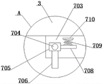
FIG. 7 is a schematic view of an outer ring structure of the present invention;
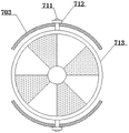
fig. 8 is a schematic view of a retainer ring mounting structure according to the present invention.
In the figure: 1. a base; 2. a support frame; 3. an upper cross beam; 4. an inclined stop block; 5. a drive mechanism; 501. a mounting frame; 502. a first motor; 503. a double-row transmission wheel; 504. a fixed mount; 505. a rotating shaft; 506. a first gear; 507. a single row of transmission wheels; 508. a second gear assembly; 509. mounting a bar; 510. a rack; 6. a stirring mechanism; 601. a stirring barrel; 602. a first separator; 603. a second motor; 604. a rotating rod; 605. a driving wheel; 606. a transmission rod; 607. a driven wheel; 608. feeding and discharging ports; 609. a limiting frame; 610. a baffle plate; 7. a feeding mechanism; 701. a charging barrel; 702. a second separator; 703. an outer ring; 704. a round bar; 705. a fixed block; 706. a support; 707. a poking plate; 708. a transverse plate; 709. a spring; 710. a top plate; 711. a connecting rod; 712. fixing a nut; 713. and (4) a baffle ring.
Detailed Description
In order to make the objects, technical solutions and advantages of the embodiments of the present application clearer, the technical solutions in the embodiments of the present application will be clearly and completely described below with reference to the drawings in the embodiments of the present application, and it is obvious that the described embodiments are some embodiments of the present application, but not all embodiments. The components of the embodiments of the present application, generally described and illustrated in the figures herein, can be arranged and designed in a wide variety of different configurations.
Thus, the following detailed description of the embodiments of the present application, as presented in the figures, is not intended to limit the scope of the claimed application, but is merely representative of selected embodiments of the application. All other embodiments, which can be derived by a person skilled in the art from the embodiments given herein without making any creative effort, shall fall within the protection scope of the present application.
It should be noted that, in the present application, the embodiments and features of the embodiments may be combined with each other without conflict.
It should be noted that: like reference numbers and letters refer to like items in the following figures, and thus, once an item is defined in one figure, it need not be further defined and explained in subsequent figures.
In the description of the embodiments of the present application, it should be noted that the indication of orientation or positional relationship is based on the orientation or positional relationship shown in the drawings, or the orientation or positional relationship which is usually placed when the product of the application is used, or the orientation or positional relationship which is usually understood by those skilled in the art, or the orientation or positional relationship which is usually placed when the product of the application is used, and is only for the convenience of describing the application and simplifying the description, but does not indicate or imply that the indicated device or element must have a specific orientation, be constructed in a specific orientation, and be operated, and thus, should not be construed as limiting the application. Furthermore, the terms "first," "second," "third," and the like are used solely to distinguish one from another and are not to be construed as indicating or implying relative importance.
In the description of the embodiments of the present application, it should also be noted that, unless otherwise explicitly stated or limited, the terms "disposed," "mounted," and "connected" are to be construed broadly, and may for example be fixedly connected, detachably connected, or integrally connected; may be directly connected or may be indirectly connected through an intermediate. The specific meaning of the above terms in the present application can be understood in a specific case by those of ordinary skill in the art.
Referring to fig. 1-8, the present invention provides a technical solution: the utility model provides an automatic continuous type concrete mixer of batching, including base 1, two sets of ann support frames 2 are installed to base 1's top symmetry, entablature 3 is installed at support frame 2's top, base 1's top surface just is located support frame 2 relative one side and installs oblique dog 4, actuating mechanism 5 is installed at base 1's top, and actuating mechanism 5's quantity is two sets of, the symmetry is installed at base 1's top surface, rabbling mechanism 6 is installed to two sets of actuating mechanism 5 relative one side, reinforced mechanism 7 is installed at entablature 3's top.
The driving mechanism 5 comprises an installation frame 501, the installation frame 501 is installed at the top of the base 1, a first motor 502 is installed at the back of the installation frame 501, a double-row transmission wheel 503 is installed at the power output end of the first motor 502, a fixed frame 504 is installed at the side edge of the installation frame 501, a rotating shaft 505 is installed inside the fixed frame 504, the rotating shaft 505 penetrates through the fixed frame 504, a first gear 506 is installed on the surface of the rotating shaft 505, a single-row transmission wheel 507 is installed at the end of the rotating shaft 505, a second gear assembly 508 is installed at the other side edge of the installation frame 501, an installation strip 509 is installed on the outer surface of the stirring mechanism 6, a rack 510 is installed on the surface of the installation strip 509, and the installation structure and the transmission structure of the second gear assembly 508 are the same as those of the first gear 506.
As a preferable embodiment of the present embodiment: the power rod is installed at the power take off end of first motor 502, and the power rod runs through mounting bracket 501 and extends to the outside, and double drive wheel 503 is installed on the extension section surface of power rod, and is connected through the transmission belt transmission between double drive wheel 503 and the single drive wheel 507, drives first gear 506 and second gear subassembly 508 rotation through first motor 502 for agitator 601 can realize the slope of left and right direction.
As a preferable embodiment of the present embodiment: the surface mounting of mount 504 has the bearing frame, and the internally mounted of bearing frame has the bearing of looks adaptation with pivot 505, and passes through the bearing rotational mounting between pivot 505 and the bearing frame, and pivot 505's length is longer, consequently needs to support through bearing frame, and then guarantees pivot 505's performance and life.
As a preferable embodiment of the present embodiment: rabbling mechanism 6 includes agitator 601, and the top of base 1 is provided with agitator 601, and the internally mounted of agitator 601 has first baffle 602, and the bottom surface mounting of agitator 601 has second motor 603, and the bull stick 604 is installed to the power take off end of second motor 603, and action wheel 605 is installed to the intermediate position department on bull stick 604 surface, drives two sets of puddlers through second motor 603 and rotates, and then realizes that two stations have improved efficiency simultaneously.
As a preferable embodiment of the present embodiment: the two sides of the first partition plate 602 are rotatably provided with the transmission rod 606, one end of the transmission rod 606 close to the driving wheel 605 is provided with the driven wheel 607, the two ends of the stirring barrel 601 are provided with the material inlet and outlet 608, one side opposite to the material inlet and outlet 608 is provided with the limiting frame 609, the inside of the material inlet and outlet 608 is provided with the baffle 610 in a sliding manner, and the stirring mechanism 6 is arranged, so that the stirring machine can adopt double-station simultaneous stirring in the using process, the stirring efficiency is improved, the feeding is convenient, the blanking is convenient, the practicability is high, and the development space is wide and the popularization value is high.
As a preferable embodiment of the present embodiment: the two sides of the first partition 602 are provided with mounting holes, and the bottom of the first partition 602 is provided with through holes adapted to the rotating rod 604, and the mounting holes are used for mounting one end of the rotating rod 604 to provide stable support.
As a preferable embodiment of the present embodiment: one end of the transmission rod 606 close to the material inlet/outlet 608 is rotatably mounted inside the limiting frame 609, one end of the rotating rod 604 is rotatably mounted inside the limiting frame 609, and the other end of the rotating rod 604 is rotatably mounted inside the first partition 602, so that the stability of the rotating rod 604 is ensured.
As a preferable aspect of the present embodiment: the feeding mechanism 7 comprises a feeding barrel 701, the top of the upper beam 3 is provided with the feeding barrel 701, a second partition plate 702 is arranged inside the feeding barrel 701, two groups of outer rings 703 are symmetrically arranged on the surface of the bottom of the feeding barrel 701, a round rod 704 is arranged on the surface of the outer rings 703, a fixed block 705 is rotatably arranged on the surface of the round rod 704, and a support 706 is arranged on the surface of the fixed block 705.
As a preferable embodiment of the present embodiment: the stirring plate 707 is installed at the top of support 706, and fixed block 705's surface mounting has diaphragm 708, and diaphragm 708's surface mounting has spring 709, and the other end of spring 709 installs roof 710, and the inside movable mounting of outer loop 703 has connecting rod 711, and the surface of connecting rod 711 is provided with the screw thread, and the surface screw thread of connecting rod 711 installs fixation nut 712, and fender ring 713 is installed to the end of connecting rod 711, through the reinforced mechanism 7 of face setting, the stirring efficiency of improvement concrete, labour saving and time saving.
As a preferable aspect of the present embodiment: the surface of the outer ring 703 is provided with a through groove matched with the connecting rod 711, the baffle ring 713 is arranged with the outer ring 703 through the connecting rod 711 and the fixing nut 712, and the blanking and the stop of the raw materials in the charging barrel 701 are controlled through the arranged baffle ring 713.
In embodiment 1, a bracket 706 is mounted on the surface of a fixed block 705, a poking plate 707 is mounted on the top of the bracket 706, a horizontal plate 708 is mounted on the surface of the fixed block 705, a spring 709 is mounted on the surface of the horizontal plate 708, and a top plate 710 is mounted at the other end of the spring 709.
In embodiment 2, the surface of the retainer ring 713 is divided into eight areas, four areas are used for blanking, the other four areas are used for blocking the blanking holes at the bottom of the charging barrel 701, when the charging device is used, the fixing nut 712 is loosened, the charging can be performed by rotating the retainer ring 713, and the retainer ring 713 is closed after the charging is completed.
The working principle is as follows: adding four raw materials into a feeding barrel 701, then driving a stirring barrel 601 to rotate through a first motor 502, opening a baffle plate 610 through a stirring plate 707 in the process that one end of the stirring barrel 601 rotates to the bottom of a feeding mechanism 7, loosening a fixing nut 712 when one end of the stirring barrel 601 is right opposite to the bottom of the feeding barrel 701, rotating the baffle ring 713 to feed materials, closing the baffle ring 713 after feeding, screwing the fixing nut 712, driving the stirring barrel 601 to reset through the reverse rotation of the first motor 502, closing the baffle plate 610 through the stirring plate 707 in the resetting process, stirring, then driving the stirring barrel 601 to reversely rotate through the first motor 502 to feed materials through the same steps at the other end, driving the stirring barrel 601 to deflect through the first motor 502 after stirring is completed, opening the baffle plate 610 to discharge materials, then driving the other end of the stirring barrel 501 to rotate to the bottom to discharge materials through the reverse rotation of the first motor 502, the other end rotates to repeat the steps for feeding, and the operation is repeated.
The above description is only a preferred embodiment of the present application and is not intended to limit the present application, and various modifications and changes may be made to the present application by those skilled in the art. Any modification, equivalent replacement, improvement and the like made within the spirit and principle of the present application shall be included in the protection scope of the present application.
Claims (8)
1. The utility model provides an automatic continuous type concrete mixer of batching, includes base (1), its characterized in that: the automatic feeding device is characterized in that two groups of supporting frames (2) are symmetrically installed at the top of the base (1), an upper cross beam (3) is installed at the top of each supporting frame (2), an inclined stop block (4) is installed on the surface of the top of the base (1) and on one side, opposite to the supporting frames (2), of the top of the base (1), two groups of driving mechanisms (5) are installed at the top of the base (1), the two groups of driving mechanisms are symmetrically installed on the surface of the top of the base (1), a stirring mechanism (6) is installed on one side, opposite to the two groups of driving mechanisms (5), and a feeding mechanism (7) is installed at the top of the upper cross beam (3);
the driving mechanism (5) comprises a mounting frame (501), the mounting frame (501) is installed at the top of the base (1), a first motor (502) is installed at the back face of the mounting frame (501), a double-row transmission wheel (503) is installed at the power output end of the first motor (502), a fixing frame (504) is installed at the side edge of the mounting frame (501), a rotating shaft (505) is installed inside the fixing frame (504), the rotating shaft (505) penetrates through the fixing frame (504), a first gear (506) is installed on the surface, located inside the fixing frame (504), of the rotating shaft (505), a single-row transmission wheel (507) is installed at the end of the rotating shaft (505), a second gear assembly (508) is installed at the other side edge of the mounting frame (501), a mounting bar (509) is installed on the outer surface of the stirring mechanism (6), and a rack (510) is installed on the surface of the mounting bar (509), the second gear assembly (508) has the same mounting structure and transmission structure as the first gear (506);
the stirring mechanism (6) comprises a stirring barrel (601), the stirring barrel (601) is arranged at the top of the base (1), a first partition plate (602) is installed inside the stirring barrel (601), a second motor (603) is installed on the surface of the bottom of the stirring barrel (601), a rotating rod (604) is installed at the power output end of the second motor (603), and a driving wheel (605) is installed in the middle position of the surface of the rotating rod (604);
reinforced mechanism (7) are including adding feed bin (701), add feed bin (701) is installed at the top of entablature (3), the internally mounted of adding feed bin (701) has second baffle (702), the bottom surface symmetry of adding feed bin (701) installs two sets of outer rings (703), the surface mounting of outer ring (703) has round bar (704), fixed block (705) are installed in the surface rotation of round bar (704), the surface mounting of fixed block (705) has support (706).
2. An automatically dispensing continuous concrete mixer according to claim 1, wherein: the power output end of the first motor (502) is provided with a power rod, the power rod penetrates through the mounting frame (501) and extends to the outside, the double-row driving wheel (503) is mounted on the surface of the extending section of the power rod, and the double-row driving wheel (503) is in transmission connection with the single-row driving wheel (507) through a transmission belt.
3. An automatically dispensing continuous concrete mixer according to claim 1, wherein: the surface of the fixing frame (504) is provided with a bearing frame, the bearing frame is internally provided with a bearing matched with the rotating shaft (505), and the rotating shaft (505) and the bearing frame are rotatably arranged through the bearing.
4. An automatically dispensing continuous concrete mixer according to claim 1, wherein: the both sides of first baffle (602) are rotated and are installed transfer line (606), the one end that transfer line (606) is close to action wheel (605) is installed from driving wheel (607), business turn over material mouth (608) are all installed at the both ends of agitator (601), spacing (609) are installed to the relative one side of business turn over material mouth (608), the inside slidable mounting of business turn over material mouth (608) has baffle (610).
5. An automatically dispensing continuous concrete mixer according to claim 1, wherein: mounting holes are formed in two sides of the first partition plate (602), and through holes matched with the rotating rods (604) are formed in the bottom of the first partition plate (602).
6. An automatically dispensing continuous concrete mixer according to claim 4, wherein: one end of the transmission rod (606) close to the material inlet and outlet (608) is rotatably arranged in the limiting frame (609).
7. An automatically dispensing continuous concrete mixer according to claim 1, wherein: the top of support (706) is installed and is dialled board (707), the surface mounting of fixed block (705) has diaphragm (708), the surface mounting of diaphragm (708) has spring (709), roof (710) are installed to the other end of spring (709), the inside movable mounting of outer ring (703) has connecting rod (711), the surface of connecting rod (711) is provided with the screw thread, and the surface threaded mounting of connecting rod (711) has fixation nut (712), fender ring (713) is installed to the end of connecting rod (711).
8. An automatically dispensing continuous concrete mixer according to claim 7, wherein: the surface of the outer ring (703) is provided with a through groove matched with the connecting rod (711), and the baffle ring (713) is installed with the outer ring (703) through the connecting rod (711) and the fixing nut (712).
Priority Applications (1)
| Application Number | Priority Date | Filing Date | Title |
|---|---|---|---|
| CN202110187068.5A CN112706292B (en) | 2021-02-18 | 2021-02-18 | Automatic continuous type concrete mixer of batching |
Applications Claiming Priority (1)
| Application Number | Priority Date | Filing Date | Title |
|---|---|---|---|
| CN202110187068.5A CN112706292B (en) | 2021-02-18 | 2021-02-18 | Automatic continuous type concrete mixer of batching |
Publications (2)
| Publication Number | Publication Date |
|---|---|
| CN112706292A CN112706292A (en) | 2021-04-27 |
| CN112706292B true CN112706292B (en) | 2022-09-09 |
Family
ID=75550166
Family Applications (1)
| Application Number | Title | Priority Date | Filing Date |
|---|---|---|---|
| CN202110187068.5A Active CN112706292B (en) | 2021-02-18 | 2021-02-18 | Automatic continuous type concrete mixer of batching |
Country Status (1)
| Country | Link |
|---|---|
| CN (1) | CN112706292B (en) |
Families Citing this family (1)
| Publication number | Priority date | Publication date | Assignee | Title |
|---|---|---|---|---|
| CN113664998B (en) * | 2021-07-30 | 2022-10-11 | 安徽三朋建材集团有限公司 | Mortar preparation system capable of simultaneously producing masonry mortar and surface mortar |
Citations (6)
| Publication number | Priority date | Publication date | Assignee | Title |
|---|---|---|---|---|
| AU2002951329A0 (en) * | 2002-09-11 | 2002-09-26 | Nepean Engineering Pty Ltd | A mixing apparatus for concrete |
| CN206663521U (en) * | 2017-04-12 | 2017-11-24 | 潘翔 | A kind of detachable concrete mixer |
| CN209552130U (en) * | 2018-07-30 | 2019-10-29 | 扬州中建建设机械有限公司 | A kind of New agitator for concrete mixing plant |
| CN210820187U (en) * | 2019-08-21 | 2020-06-23 | 芜湖实泰机械制造有限公司 | Cement mixer convenient to unloading |
| CN211466946U (en) * | 2019-08-21 | 2020-09-11 | 郑州医笃筑工智能科技有限公司 | Concrete mixer for municipal building |
| CN211762536U (en) * | 2019-12-31 | 2020-10-27 | 南京五环新型材料科技有限公司 | Concrete mixer for building engineering |
-
2021
- 2021-02-18 CN CN202110187068.5A patent/CN112706292B/en active Active
Patent Citations (6)
| Publication number | Priority date | Publication date | Assignee | Title |
|---|---|---|---|---|
| AU2002951329A0 (en) * | 2002-09-11 | 2002-09-26 | Nepean Engineering Pty Ltd | A mixing apparatus for concrete |
| CN206663521U (en) * | 2017-04-12 | 2017-11-24 | 潘翔 | A kind of detachable concrete mixer |
| CN209552130U (en) * | 2018-07-30 | 2019-10-29 | 扬州中建建设机械有限公司 | A kind of New agitator for concrete mixing plant |
| CN210820187U (en) * | 2019-08-21 | 2020-06-23 | 芜湖实泰机械制造有限公司 | Cement mixer convenient to unloading |
| CN211466946U (en) * | 2019-08-21 | 2020-09-11 | 郑州医笃筑工智能科技有限公司 | Concrete mixer for municipal building |
| CN211762536U (en) * | 2019-12-31 | 2020-10-27 | 南京五环新型材料科技有限公司 | Concrete mixer for building engineering |
Also Published As
| Publication number | Publication date |
|---|---|
| CN112706292A (en) | 2021-04-27 |
Similar Documents
| Publication | Publication Date | Title |
|---|---|---|
| CN211541798U (en) | Automatic concrete production device | |
| CN112706292B (en) | Automatic continuous type concrete mixer of batching | |
| CN211250807U (en) | High-discharging-efficiency autoclaved aerated concrete slurry stirring tank | |
| CN209775129U (en) | Cement stirring device | |
| CN111300654A (en) | Intermittent type formula ready-mixed mortar cement concrete agitating unit | |
| CN114307834A (en) | Quantitative mixing production equipment for water reducing agent | |
| CN211074175U (en) | Concrete autoloading agitating unit | |
| CN210999403U (en) | Concrete mixer capable of stirring uniformly | |
| CN214555070U (en) | Automatic screening device for concrete materials | |
| CN212417847U (en) | Feeding device of stirrer | |
| CN210791523U (en) | Mixing device for production of explosion-proof mortar | |
| CN210999395U (en) | Stirring's gravity formula concrete mixer | |
| CN214353451U (en) | Stirring efficient raw material mixing device for plastic bag production | |
| CN212795418U (en) | Gravel and sand agitating unit is used in concrete production | |
| CN208215669U (en) | A kind of agitating device of self-leveling cement | |
| CN220903735U (en) | Construction concrete compounding jar | |
| CN220052300U (en) | Mixing device for manufacturing concrete drain pipe | |
| CN220513954U (en) | Mixing box for building construction | |
| CN216139180U (en) | Efficient unloading mechanism for crude sand silo | |
| CN219076101U (en) | Proportioning machine for ready-mixed concrete | |
| CN219650258U (en) | Premixed masonry mortar mixing device | |
| CN212421746U (en) | Ecological soil cement utilizes earth agitating unit convenient to fall material | |
| CN220075121U (en) | Automatic concrete mixer of material loading | |
| CN208584662U (en) | A kind of novel architecture concrete uniform stirring equipment | |
| CN220129085U (en) | Feeding device for manufacturing concrete structural member |
Legal Events
| Date | Code | Title | Description |
|---|---|---|---|
| PB01 | Publication | ||
| PB01 | Publication | ||
| SE01 | Entry into force of request for substantive examination | ||
| SE01 | Entry into force of request for substantive examination | ||
| TA01 | Transfer of patent application right | ||
| TA01 | Transfer of patent application right |
Effective date of registration: 20220817 Address after: Tantou Village Group, Zhangjia Village, Renwan Town, Lengshuitan District, Yongzhou City, Hunan Province 425000 Applicant after: Yongzhou Dongping Building Materials Co., Ltd. Address before: No.36, group 6, Taipingjie village, Gulin Town, Gulin County, Luzhou City, Sichuan Province, 646500 Applicant before: Hu Bing |
|
| GR01 | Patent grant | ||
| GR01 | Patent grant |