CN112681453B - Bury formula integration fire pump station - Google Patents
Bury formula integration fire pump station Download PDFInfo
- Publication number
- CN112681453B CN112681453B CN202011347325.9A CN202011347325A CN112681453B CN 112681453 B CN112681453 B CN 112681453B CN 202011347325 A CN202011347325 A CN 202011347325A CN 112681453 B CN112681453 B CN 112681453B
- Authority
- CN
- China
- Prior art keywords
- box body
- wall
- plate
- water
- fixed
- Prior art date
- Legal status (The legal status is an assumption and is not a legal conclusion. Google has not performed a legal analysis and makes no representation as to the accuracy of the status listed.)
- Active
Links
Images


Abstract
The invention discloses a buried integrated fire-fighting pump station, which comprises: the base, the vertical box that is provided with of base upper surface, box top right side is provided with the access hole, bottom half left side wall transversely is provided with the inlet tube, the inside intermediate position of box transversely is provided with the platform, the platform upper surface is provided with the fixing base, the upper surface of fixing base is provided with first motor, the output of first motor is provided with the water pump, the water pump is located on the fixing base, the output of water pump is provided with the outlet pipe, and this device passes through the cooperation of rotary drum, even axle, chain and desilting mechanism isotructure and connects, has realized carrying out automatic cleaning to a large amount of precipitations of bottom half, has avoided the long-term deposit of some debris to corrode the bottom half wall, cleans effectually, and is efficient.
Description
Technical Field
The invention relates to the technical field of drainage equipment, in particular to a buried integrated fire pump station.
Background
The pump station is the only power source for providing potential energy and pressure energy for water and solving the problems of drainage and irrigation, water supply and water resource allocation under the condition of no self-flow. The integrated pump station mainly comprises a forming cylinder, a sewage pump, an overhaul platform, an escalator, a water inlet pipeline, a water outlet pipeline, an automatic coupling device, an automatic control system and the like. The device is mainly used for collecting and discharging municipal sewage, rainwater and the like, and is installed in a buried or semi-underground manner. The bottom of the existing integrated pump station barrel is mostly in a plane mode, water flow carries impurities to enter the barrel, and the impurities fall to the bottom under the action of dead weight to form sediment and are accumulated at the bottom. The impurity of the near regional of some water pump can be taken away because the effect of water flow state when the water pump extraction water, but the region far away from the water pump has the regional deposit of part all the time and can't be siphoned away, forms the dead angle, can form a large amount of deposits along with the lapse of time, corrodes the barrel, needs often to clear up, wastes time and energy, is mingled with a large amount of impurity in the water simultaneously, can influence pump body work for a long time, to above-mentioned problem, needs to improve current equipment.
Disclosure of Invention
The invention aims to solve the technical problem of providing a buried integrated fire pump station capable of automatically cleaning a large amount of sediments.
The technical problem to be solved by the invention is realized by adopting the following technical scheme: a buried integrated fire pump station, comprising:
the water pump comprises a base, wherein a box body is vertically arranged on the upper surface of the base, an access hole is formed in the right side of the top of the box body, a water inlet pipe is transversely arranged on the left side wall of the bottom of the box body, a platform is transversely arranged in the middle of the interior of the box body, a fixed seat is arranged on the upper surface of the platform, a first motor is arranged on the upper surface of the fixed seat, a water pump is arranged at the output end of the first motor, the water pump is located on the fixed seat, a water outlet pipe is arranged at the output end of the water pump, the water outlet pipe extends to the top of the box body, a water inlet pipe is arranged at the input end of the water pump, a water tank is connected to the right end of the water inlet pipe, a guide pipe is connected to the right side of the water tank, and the guide pipe extends to the lower part of the platform;
the self-cleaning mechanism is arranged at the bottom of the box body and comprises a shell arranged on the right side wall of the bottom of the box body, a second motor is arranged in the shell, the output end of the second motor is provided with a rotating shaft, the rotating shaft extends leftwards into the box body, the left end of the rotating shaft extends into the water inlet pipe, the surface of the rotating shaft is fixedly sleeved with a rotating cylinder, the outer wall of the rotating cylinder is provided with a special-shaped guide groove, the front side below the rotating cylinder is provided with a pair of first bearing seats corresponding to the inner wall of the bottom of the box body, the first bearing seats are vertically provided with fixed shafts, the top ends of the fixed shafts are respectively provided with fixed wheels, chains are meshed with each other between the fixed wheels, the upper surfaces of the chains are provided with fixed plates at equal intervals, the tops of the fixed plates are vertically provided with limiting rods, and the top ends of the limiting rods are positioned in the guide grooves, and the lower surfaces of the chains are provided with dredging mechanisms at equal intervals.
Further, desilting mechanism is including setting up the connecting plate of chain lower surface, setting are in the solid fixed cylinder of connecting plate bottom, the inside activity of solid fixed cylinder is provided with movable post, the top of activity post is provided with first spring, first spring top with connecting plate fixed connection, the bottom level of activity post is provided with the horizontal plate, the lower surface of horizontal plate evenly is provided with first brush, first brush with the bottom half inner wall offsets.
Further, the left end outer wall annular of pivot is provided with the connecting rod, the outer end of connecting rod is provided with the spacing ring, the spacing ring rotates to set up and is being located in the ring channel of inlet pipe inner wall, the limiting plate with connecting rod handing-over department transversely is provided with the cleaning plate, the cleaning plate inner wall is provided with the fourth brush, the fourth brush with the inlet pipe inner wall offsets.
Further, the guide groove is an integral groove.
Furthermore, an exhaust port is arranged on the left side of the top of the box body.
Further, the top of the shell is vertically provided with a wire pipe.
Furthermore, the front end of the water inlet pipe is provided with a filter cover.
The invention has the beneficial effects that: this device passes through the rotary drum, even axle, the cooperation of chain and desilting mechanism isotructure is connected, realized depositing in a large number and carrying out the automation to the bottom half and clean, the long-term deposit of having avoided some debris to corrode the bottom wall of the box, clean effectually, high efficiency, time saving and labor saving, in addition, through the slide, the second rack, the guide pillar and scrub the cooperation of mechanism isotructure and connect, realized scrubbing the high efficiency on filter screen surface, avoid impurity attached to filter screen surface influence filter effect, effectively avoid silt jam to influence the sewage lifting operation at the filter screen, water pump normal operating has been guaranteed.
Description of the drawings:
FIG. 1 is a schematic view of the overall structure of the present invention;
FIG. 2 is a top view of the chain position of the present invention;
FIG. 3 is a schematic structural diagram of the dredging mechanism of the present invention;
FIG. 4 is a schematic view showing the internal structure of the water tank of the present invention;
FIG. 5 is a schematic side view of the water inlet pipe of the present invention;
FIG. 6 is a schematic view of the internal structure of the water inlet pipe of the present invention;
FIG. 7 is a schematic view of the overall structure in embodiment 2 of the present invention;
FIG. 8 is a schematic structural view of the ash removal mechanism of the present invention;
FIG. 9 is a schematic structural view of the frame of the present invention;
FIG. 10 is a cross-sectional view of the frame of the present invention;
FIG. 11 is a schematic view of the construction of the skateboard of the present invention;
FIG. 12 is a cross-sectional view of the guide rail of the present invention;
FIG. 13 is a schematic view of the access door of the present invention;
fig. 14 is a schematic structural view of the driving mechanism of the present invention.
Reference numbers in the figures: 10. a base; 11. a box body; 12. a water inlet pipe; 121. a filter housing; 122. an annular groove; 13. an exhaust port; 14. a ladder; 15. an access hole; 20. a platform; 21. a fixed seat; 22. a first motor; 23. a water inlet pipe; 24. a water pump; 25. a water outlet pipe; 26. a water tank; 27. a conduit; 30. a housing; 301. a conduit; 31. a second motor; 32. a rotating shaft; 33. a rotating drum; 331. a guide groove; 34. a chain; 35. a fixed shaft; 36. a fixed wheel; 37. a first bearing housing; 38. a dredging mechanism; 381. a connecting plate; 382. a fixed cylinder; 383. a first spring; 384. a movable post; 385. a transverse plate; 386. a first brush; 39. a fixing plate; 391. a limiting rod; 40. a dust removal mechanism; 41. a frame; 411. a filter screen; 412. a partition plate; 413. a strip-shaped hole; 414. a first rack; 415. a limiting plate; 416. a limiting hole; 417. mounting a plate; 42. erecting a frame; 43. a guide plate; 431. a chute; 44. a guide rail; 441. a dovetail groove; 442. a slider; 45. a slide plate; 451. a guide hole; 46. a driving wheel; 47. a long plate; 48. a guide post; 49. a second rack; 50. a brushing mechanism; 51. a connecting shaft; 52. a second brush; 53. a transverse bar; 54. a third brush; 55. a second bearing housing; 56. fixing the rod; 57. a gear; 60. a limiting ring; 61. a connecting rod; 62. cleaning the plate; 63. a fourth brush; 70. an access door; 71. a fixed seat; 72. a fixed block; 73. a door body; 74. a connecting member; 75. a plate body; 751. a first hinge member; 76. a first rod body; 761. a second hinge member; 77. a second rod body; 771. a circular plate; 78. a shaft body; 80. a drive mechanism; 81. a sleeve; 82. a first piston; 83. a third rack; 84. a transmission gear; 85. a barrel; 86. a second piston; 87. a second spring.
The specific implementation mode is as follows:
in order to make the technical means, the creation characteristics, the achievement purposes and the effects of the invention easy to understand, the invention is further explained below by combining the specific drawings.
It will be understood that when an element is referred to as being "secured to" another element, it can be on the other element or intervening elements may also be present. When an element is referred to as being "connected" to another element, it can be directly connected to the other element or intervening elements may also be present. The terms "vertical," "horizontal," "left," "right," and similar expressions are used herein for illustrative purposes only and do not represent the only embodiments.
Example 1
As shown in fig. 1-6, the invention provides a buried integrated fire pump station, comprising:
the water-saving and water-saving device comprises a base 10, wherein a box body 11 is vertically arranged on the upper surface of the base 10, an access hole 15 is formed in the right side of the top of the box body 11, a water inlet pipe 12 is transversely arranged on the left side wall of the bottom of the box body 10, a platform 20 is transversely arranged in the middle of the interior of the box body 10, a fixed seat 21 is arranged on the upper surface of the platform 20, a first motor 22 is arranged on the upper surface of the fixed seat 21, a water pump 24 is arranged at the output end of the first motor 22, the water pump 24 is located on the fixed seat 21, a water outlet pipe 25 is arranged at the output end of the water pump 24, the water outlet pipe 25 extends to the top of the box body 10, a water inlet pipe 23 is arranged at the input end of the water pump 24, a water tank 26 is connected to the right end of the water inlet pipe 23, a guide pipe 27 is connected to the right side of the water tank 26, and the guide pipe 27 extends to the lower side of the platform 20;
the self-cleaning mechanism is arranged at the bottom of the box body 10, the self-cleaning mechanism comprises a shell 30 arranged at the right side wall of the bottom of the box body 10, a second motor 31 is arranged in the shell 30, the output end of the second motor 31 is provided with a rotating shaft 32, the rotating shaft 32 extends leftwards to the inside of the box body 10, the left end of the rotating shaft 32 extends into the water inlet pipe 12, a rotating drum 33 is fixedly sleeved on the surface of the rotating shaft 32, the outer wall of the rotating drum 33 is provided with a special-shaped guide groove 331, the front side below the rotating drum 33 is provided with a pair of first bearing seats 37 corresponding to the inner wall of the bottom of the box body 10, a fixed shaft 35 is vertically arranged on the first bearing seats 37, fixed wheels 36 are arranged at the top ends of the fixed shafts 35, chains 34 are meshed with each other between the fixed wheels 36, and fixed plates 39 are arranged on the upper surfaces of the chains 34 at equal intervals, a limiting rod 391 is vertically arranged at the top of the fixing plate 39, the top end of the limiting rod 391 is positioned in the guide groove 331, and the lower surface of the chain 34 is provided with dredging mechanisms 38 at equal intervals;
the dredging mechanism 38 comprises a connecting plate 381 arranged on the lower surface of the chain 34 and a fixed cylinder 382 arranged at the bottom of the connecting plate 381, a movable column 384 is movably arranged in the fixed cylinder 382, a first spring 383 is arranged at the top of the movable column 384, the top of the first spring 383 is fixedly connected with the connecting plate 381, a transverse plate 385 is horizontally arranged at the bottom of the movable column 384, a first brush 386 is uniformly arranged on the lower surface of the transverse plate 385, and the first brush 386 is abutted to the inner wall of the bottom of the box 10.
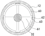
The left end outer wall annular of pivot 32 is provided with connecting rod 61, the outer end of connecting rod 61 is provided with spacing ring 60, spacing ring 60 rotates to set up and is being located in the ring channel 122 of inlet tube 12 inner wall, limiting plate 60 with connecting rod 61 handing-over department transversely is provided with cleaning plate 62, cleaning plate 62 inner wall is provided with fourth brush 63, fourth brush 63 with inlet tube 12 inner wall offsets.
The guide slot 331 is an integral slot, and in particular, the guide slot 331 can make the chain 34 rotate forward and backward under the cooperation of the limiting rod 391.
An exhaust port 13 is arranged on the left side of the top of the box body 10.
A conduit 301 is vertically arranged on the top of the housing 30, and the guide can be connected with the second motor 31 through the conduit 301.
The front end of the water inlet pipe 12 is provided with a filter cover 121.
Example 2
As shown in fig. 1 to 14, the present invention provides a buried integrated fire pump station, comprising:
the water-saving and water-saving device comprises a base 10, wherein a box body 11 is vertically arranged on the upper surface of the base 10, an access hole 15 is formed in the right side of the top of the box body 11, a water inlet pipe 12 is transversely arranged on the left side wall of the bottom of the box body 10, a platform 20 is transversely arranged in the middle of the interior of the box body 10, a fixed seat 21 is arranged on the upper surface of the platform 20, a first motor 22 is arranged on the upper surface of the fixed seat 21, a water pump 24 is arranged at the output end of the first motor 22, the water pump 24 is located on the fixed seat 21, a water outlet pipe 25 is arranged at the output end of the water pump 24, the water outlet pipe 25 extends to the top of the box body 10, a water inlet pipe 23 is arranged at the input end of the water pump 24, a water tank 26 is connected to the right end of the water inlet pipe 23, a guide pipe 27 is connected to the right side of the water tank 26, and the guide pipe 27 extends to the lower side of the platform 20;
the self-cleaning mechanism is arranged at the bottom of the box body 10, the self-cleaning mechanism comprises a shell 30 arranged at the right side wall of the bottom of the box body 10, a second motor 31 is arranged in the shell 30, the output end of the second motor 31 is provided with a rotating shaft 32, the rotating shaft 32 extends leftwards to the inside of the box body 10, the left end of the rotating shaft 32 extends into the water inlet pipe 12, a rotating drum 33 is fixedly sleeved on the surface of the rotating shaft 32, the outer wall of the rotating drum 33 is provided with a special-shaped guide groove 331, the front side below the rotating drum 33 is provided with a pair of first bearing seats 37 corresponding to the inner wall of the bottom of the box body 10, a fixed shaft 35 is vertically arranged on the first bearing seats 37, fixed wheels 36 are arranged at the top ends of the fixed shafts 35, chains 34 are meshed with each other between the fixed wheels 36, and fixed plates 39 are arranged on the upper surfaces of the chains 34 at equal intervals, a limiting rod 391 is vertically arranged at the top of the fixing plate 39, the top end of the limiting rod 391 is positioned in the guide groove 331, and the lower surface of the chain 34 is provided with dredging mechanisms 38 at equal intervals;
the ash cleaning mechanism 40 is arranged above the self-cleaning mechanism, the ash cleaning mechanism 40 comprises a frame 41 transversely arranged on the inner wall of the box body 10, a mounting plate 417 is arranged on the left side of the frame 41, a partition plate 412 is transversely arranged in the middle of the frame 41, filter screens 411 are arranged on two sides of the partition plate 412, a strip-shaped hole 413 is arranged in the middle of the partition plate 412, a first rack 414 is arranged on the inner wall of the strip-shaped hole 413 along the long edge, a limit plate 415 is transversely arranged at the bottom of the partition plate 412, a limit hole 416 is transversely arranged on the limit plate 415, the limit hole 416 corresponds to the position of the strip-shaped hole 413, a pair of vertical frames 42 is vertically arranged at the bottom of the mounting plate 417, a guide rail 44 is transversely arranged between the vertical frames 42 corresponding to the bottom of the mounting plate 417, and a dovetail groove 441 is formed in the middle position of the surface of the guide rail 44 along the long edge, a sliding block 442 is slidably arranged in the dovetail groove 441, a sliding plate 45 is transversely arranged on the outer wall of the sliding block 442, a guide hole 451 is obliquely arranged on the surface of the sliding plate 45, a pair of guide plates 43 is longitudinally arranged at the bottom end of the stand 42, a sliding groove 431 is arranged on the inner wall of each guide plate 43, a second rack 49 is slidably arranged in the sliding groove 431, a guide post 48 is vertically arranged at the middle position of the back surface of the second rack 49, the guide post 48 is inserted in the guide hole 451, a transmission wheel 46 is arranged on the left side of the rotating shaft 32, the second rack 49 is meshed with the transmission wheel 46, a long plate 47 is transversely arranged on the right side wall of the sliding plate 45, and the long plate 47 is provided with a brushing mechanism 50 at equal intervals;
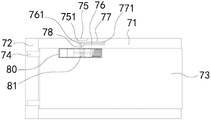
the access door, the access door sets up access opening 15 top, the access door is including setting up fixing base 71, the setting that is in access opening 15 outer edge are in the door body 73 at fixing base 71 top, the left end upper surface of fixing base 71 is provided with a pair of fixed block 72, the inboard of fixed block 72 is rotated through connecting piece 74 and is provided with the door body 73, upper surface one side of fixing base 71 is provided with plate body 75, plate body 75 inboard is provided with first body of rod 77 through first articulated elements 751, the front end of first body of rod 77 is through second articulated elements 771 parallel arrangement second body of rod 76, the front end of second body of rod 76 is provided with plectane 761, the outer wall of plectane 761 is fixed and is provided with axis body 78, axis body 78 is connected with actuating mechanism 80, actuating mechanism 80 is including setting up the barrel 85 on door body 73 outer edge in surface, the inside left end activity of barrel 85 is provided with first piston 82, the inside right-hand member activity of barrel 85 is provided with second piston 86, be provided with third rack 83 between first piston 82 and the second piston 86 top, the axis body 78 sets up the below of third rack 83, and the axis body 78 with third rack 83 mutually perpendicular, the fixed cover of axis body 78 outer wall is equipped with sleeve 81, sleeve 81 outer wall intermediate position is provided with driving gear 84, driving gear 84 with third rack 83 intermeshing, second piston 86 right side wall with be provided with second spring 87 between the barrel 85 inner wall.
The dredging mechanism 38 comprises a connecting plate 381 arranged on the lower surface of the chain 34 and a fixed cylinder 382 arranged at the bottom of the connecting plate 381, a movable column 384 is movably arranged in the fixed cylinder 382, a first spring 383 is arranged at the top of the movable column 384, the top of the first spring 383 is fixedly connected with the connecting plate 381, a transverse plate 385 is horizontally arranged at the bottom of the movable column 384, a first brush 386 is uniformly arranged on the lower surface of the transverse plate 385, and the first brush 386 is abutted to the inner wall of the bottom of the box 10.
The left end outer wall annular of pivot 32 is provided with connecting rod 61, the outer end of connecting rod 61 is provided with spacing ring 60, spacing ring 60 rotates to set up and is being located in the ring channel 122 of inlet tube 12 inner wall, limiting plate 60 with connecting rod 61 handing-over department transversely is provided with cleaning plate 62, cleaning plate 62 inner wall is provided with fourth brush 63, fourth brush 63 with inlet tube 12 inner wall offsets.
The guide groove 331 is an integral groove.
An exhaust port 13 is arranged on the left side of the top of the box body 10.
A conduit 301 is vertically arranged on the top of the housing 30, and the guide can be connected with the second motor 31 through the conduit 301.
The front end of the water inlet pipe 12 is provided with a filter cover 121.
The working process is as follows: firstly, the second motor 31 is started, the second motor 31 drives the rotating shaft 32 to rotate forward and backward, the rotating shaft 32 drives the rotating drum 33 to rotate forward and backward, the limiting rod 391 can be movably arranged in the guide groove 331 under the rotation of the rotating drum 33, so as to realize the movement of the limiting rod 391, finally, the limiting rod 391 drives the chain 34 to rotate, the chain 34 drives the dredging mechanism 38 to rotate, so as to realize the dredging of the bottom wall of the box 10, meanwhile, the left end of the rotating shaft 32 drives the limiting ring 60 to rotate, the limiting ring 60 drives the cleaning plate 62 to rotate, so that the cleaning plate 62 drives the fourth brush 63 to clean the inner wall of the water inlet pipe 12, so as to avoid the blockage of the water inlet pipe 12, when the filter screen 411 needs to be cleaned, the driving wheel 46 drives the second rack 49 to move back and forth, the second rack 49 drives the guide post 48 to move back and forth in the guide hole 451, so that the sliding plate 45 realizes the left and right reciprocating movement under the limiting action of the guide rail 44, thereby drive long board 47 and remove about, and then realize that scrubbing mechanism 50 removes about on the filter screen, realize the cleaning performance, in addition, when connecting axle 51 removes about, gear 57 and the first rack 414 intermeshing of connecting axle 51 outer wall to realize connecting axle 51 can realize the rotation function when removing, promoted the cleaning performance.
This device passes through the rotary drum, even axle, the cooperation of chain and desilting mechanism isotructure is connected, realized depositing in a large number and carrying out the automation and clean to the bottom half, some long-term deposit of debris has been avoided corroding the bottom wall of the box, clean effectually, high efficiency, time saving and labor saving, in addition, through the slide, the second rack, guide pillar and the cooperation of scrubbing mechanism isotructure are connected, the high efficiency that has realized the filter screen surface is scrubbed, avoid impurity to adhere to on the filter screen surface to influence the filter effect, effectively avoid silt jam to influence sewage lifting operation at the filter screen, the water pump normal operating has been guaranteed, in addition, through the fixing base, the cooperation of connecting rod and actuating mechanism isotructure is connected, can realize access door self-closing, guarantee that the access hole seals for a long time, the security performance is high, effectively reduce the risk that personnel fall from the access hole. The foregoing shows and describes the general principles and broad features of the present invention and advantages thereof. It will be understood by those skilled in the art that the present invention is not limited to the embodiments described above, which are described in the specification and illustrated only to illustrate the principle of the present invention, but that various changes and modifications may be made therein without departing from the spirit and scope of the present invention, which fall within the scope of the invention as claimed. The scope of the invention is defined by the appended claims and equivalents thereof.
Claims (6)
1. The utility model provides a bury formula integration fire control pump station which characterized in that includes:
the water pump comprises a base, wherein a box body is vertically arranged on the upper surface of the base, an access hole is formed in the right side of the top of the box body, a water inlet pipe is transversely arranged on the left side wall of the bottom of the box body, a platform is transversely arranged in the middle of the interior of the box body, a fixed seat is arranged on the upper surface of the platform, a first motor is arranged on the upper surface of the fixed seat, a water pump is arranged at the output end of the first motor, the water pump is located on the fixed seat, a water outlet pipe is arranged at the output end of the water pump, the water outlet pipe extends to the top of the box body, a water inlet pipe is arranged at the input end of the water pump, a water tank is connected to the right end of the water inlet pipe, a guide pipe is connected to the right side of the water tank, and the guide pipe extends to the lower part of the platform;
the self-cleaning mechanism is arranged at the bottom of the box body and comprises a shell arranged on the right side wall of the bottom of the box body, a second motor is arranged in the shell, the output end of the second motor is provided with a rotating shaft, the rotating shaft extends leftwards into the box body, the left end of the rotating shaft extends into the water inlet pipe, the surface of the rotating shaft is fixedly sleeved with a rotating cylinder, the outer wall of the rotating cylinder is provided with a special-shaped guide groove, the inner wall of the bottom of the box body is provided with a pair of first bearing seats corresponding to the front side below the rotating cylinder, the first bearing seats are vertically provided with fixed shafts, the top ends of the fixed shafts are provided with fixed wheels, chains are meshed with each other, the upper surfaces of the chains are provided with fixed plates at equal intervals, the tops of the fixed plates are vertically provided with limiting rods, and the top ends of the limiting rods are positioned in the guide grooves, the lower surfaces of the chains are provided with dredging mechanisms at equal intervals;
the left end outer wall annular of pivot is provided with the connecting rod, the outer end of connecting rod is provided with the spacing ring, the spacing ring rotates to be set up and is being located in the ring channel of inlet tube inner wall, the limiting plate with connecting rod handing-over department transversely is provided with the cleaning plate, the cleaning plate inner wall is provided with the fourth brush, the fourth brush with the inlet tube inner wall offsets.
2. The buried integrated fire pump station according to claim 1, wherein the dredging mechanism comprises a connecting plate arranged on the lower surface of the chain and a fixed cylinder arranged at the bottom of the connecting plate, a movable column is movably arranged in the fixed cylinder, a first spring is arranged at the top of the movable column, the top of the first spring is fixedly connected with the connecting plate, a transverse plate is horizontally arranged at the bottom of the movable column, first brushes are uniformly arranged on the lower surface of the transverse plate, and the first brushes abut against the inner wall of the bottom of the box body.
3. The underground integrated fire pump station according to claim 1, wherein the guide groove is an integral groove.
4. The underground integrated fire pump station according to claim 1, wherein an exhaust port is arranged on the left side of the top of the box body.
5. The underground integrated fire pump station according to claim 1, wherein a conduit is vertically arranged at the top of the housing.
6. The underground integrated fire pump station according to claim 1, wherein a filter hood is arranged at the front end of the water inlet pipe.
Priority Applications (1)
| Application Number | Priority Date | Filing Date | Title |
|---|---|---|---|
| CN202011347325.9A CN112681453B (en) | 2020-11-26 | 2020-11-26 | Bury formula integration fire pump station |
Applications Claiming Priority (1)
| Application Number | Priority Date | Filing Date | Title |
|---|---|---|---|
| CN202011347325.9A CN112681453B (en) | 2020-11-26 | 2020-11-26 | Bury formula integration fire pump station |
Publications (2)
| Publication Number | Publication Date |
|---|---|
| CN112681453A CN112681453A (en) | 2021-04-20 |
| CN112681453B true CN112681453B (en) | 2022-04-22 |
Family
ID=75446818
Family Applications (1)
| Application Number | Title | Priority Date | Filing Date |
|---|---|---|---|
| CN202011347325.9A Active CN112681453B (en) | 2020-11-26 | 2020-11-26 | Bury formula integration fire pump station |
Country Status (1)
| Country | Link |
|---|---|
| CN (1) | CN112681453B (en) |
Citations (6)
| Publication number | Priority date | Publication date | Assignee | Title |
|---|---|---|---|---|
| JP5577481B2 (en) * | 2010-01-15 | 2014-08-27 | 虎男 井上 | Pumping mud method and pumping equipment |
| CN204326234U (en) * | 2014-07-24 | 2015-05-13 | 南京贝德环保设备制造有限公司 | A kind of integrated pump station with self-cleaning function |
| CN204590919U (en) * | 2015-03-18 | 2015-08-26 | 金钢狼有限公司 | A kind of door closer |
| CN108396693A (en) * | 2017-08-07 | 2018-08-14 | 朱壮壮 | A kind of mounted road cleaning agency |
| CN207856394U (en) * | 2017-10-18 | 2018-09-14 | 广东东华园林绿化工程有限公司 | A kind of precipitation pool structure for river sewage processing |
| CN211499143U (en) * | 2019-07-22 | 2020-09-15 | 盐城方行集团有限公司 | Prefabricated pump station with structure of making an uproar is fallen |
-
2020
- 2020-11-26 CN CN202011347325.9A patent/CN112681453B/en active Active
Patent Citations (6)
| Publication number | Priority date | Publication date | Assignee | Title |
|---|---|---|---|---|
| JP5577481B2 (en) * | 2010-01-15 | 2014-08-27 | 虎男 井上 | Pumping mud method and pumping equipment |
| CN204326234U (en) * | 2014-07-24 | 2015-05-13 | 南京贝德环保设备制造有限公司 | A kind of integrated pump station with self-cleaning function |
| CN204590919U (en) * | 2015-03-18 | 2015-08-26 | 金钢狼有限公司 | A kind of door closer |
| CN108396693A (en) * | 2017-08-07 | 2018-08-14 | 朱壮壮 | A kind of mounted road cleaning agency |
| CN207856394U (en) * | 2017-10-18 | 2018-09-14 | 广东东华园林绿化工程有限公司 | A kind of precipitation pool structure for river sewage processing |
| CN211499143U (en) * | 2019-07-22 | 2020-09-15 | 盐城方行集团有限公司 | Prefabricated pump station with structure of making an uproar is fallen |
Also Published As
| Publication number | Publication date |
|---|---|
| CN112681453A (en) | 2021-04-20 |
Similar Documents
| Publication | Publication Date | Title |
|---|---|---|
| CN112156522A (en) | Prevent to block up and quality of water purification preliminary treatment pipeline that can dredge automatically | |
| CN210562554U (en) | Sewage pipeline blocks sediment scrubbing device | |
| CN209426735U (en) | Engineering slag-soil truck cleaning device | |
| CN214497823U (en) | Filtering mechanism of sewage pump station | |
| CN214574496U (en) | Sponge city construction's rainfall flood processing system | |
| CN207360285U (en) | A kind of car washer | |
| CN112681453B (en) | Bury formula integration fire pump station | |
| CN112681454B (en) | Bottom self-cleaning buried fire pump station | |
| CN112663728B (en) | Buried fire pump station with access hole capable of being automatically closed | |
| CN112922134A (en) | Dredging device for urban construction underground drainage pipe network | |
| CN211411104U (en) | Novel environmental protection sewage treatment device | |
| CN216339956U (en) | Assembled waste fitting discharging for building | |
| CN114920425B (en) | Constructed wetland purification method rainwater retrieval and utilization device | |
| CN217175007U (en) | River course clean-up equipment for hydraulic engineering | |
| CN220527990U (en) | Photovoltaic support with rainwater collection structure | |
| CN213530011U (en) | Drainage pipe belt cleaning device for deep basal pit | |
| CN218323106U (en) | Water supply and drainage system for stone production | |
| CN211947940U (en) | Bridge drainage equipment for municipal bridge engineering | |
| CN216360780U (en) | Ditch lateral wall dredging device with flushing mechanism for hydraulic engineering | |
| CN220414467U (en) | Basement drainage equipment with scrubbing function | |
| CN220266803U (en) | Prefabricated pump station with desilting structure | |
| CN217340309U (en) | Automatic cleaning device for building electromechanical equipment | |
| CN220666132U (en) | Unpowered dirt cleaning device | |
| CN219710447U (en) | Rainwater collection device of urban pipe network | |
| CN215085491U (en) | Sewage treatment device with multistage particulate matter precipitation mechanism |
Legal Events
| Date | Code | Title | Description |
|---|---|---|---|
| PB01 | Publication | ||
| PB01 | Publication | ||
| SE01 | Entry into force of request for substantive examination | ||
| SE01 | Entry into force of request for substantive examination | ||
| GR01 | Patent grant | ||
| GR01 | Patent grant | ||
| CP03 | Change of name, title or address |
Address after: Factory Building 1 # in Taoshan Industrial Park, Gangji Town, Changfeng County, Hefei City, Anhui Province, 231139 Patentee after: Anhui Haocheng Water Supply Equipment Manufacturing Co.,Ltd. Address before: 231131 room 2901, building 1, kanghuiyuan, C2 District, Century City, west of Mengcheng North Road, Shuangdun Town, Changfeng County, Hefei City, Anhui Province Patentee before: Anhui Haocheng Water Supply Engineering Co.,Ltd. |
|
| CP03 | Change of name, title or address |