CN112670873B - Be used for high heat dissipation switch board of electric power - Google Patents
Be used for high heat dissipation switch board of electric power Download PDFInfo
- Publication number
- CN112670873B CN112670873B CN202110133558.7A CN202110133558A CN112670873B CN 112670873 B CN112670873 B CN 112670873B CN 202110133558 A CN202110133558 A CN 202110133558A CN 112670873 B CN112670873 B CN 112670873B
- Authority
- CN
- China
- Prior art keywords
- fixed
- vertical
- light partition
- main body
- heat dissipation
- Prior art date
- Legal status (The legal status is an assumption and is not a legal conclusion. Google has not performed a legal analysis and makes no representation as to the accuracy of the status listed.)
- Active
Links
Images


Classifications
-
- Y—GENERAL TAGGING OF NEW TECHNOLOGICAL DEVELOPMENTS; GENERAL TAGGING OF CROSS-SECTIONAL TECHNOLOGIES SPANNING OVER SEVERAL SECTIONS OF THE IPC; TECHNICAL SUBJECTS COVERED BY FORMER USPC CROSS-REFERENCE ART COLLECTIONS [XRACs] AND DIGESTS
- Y02—TECHNOLOGIES OR APPLICATIONS FOR MITIGATION OR ADAPTATION AGAINST CLIMATE CHANGE
- Y02A—TECHNOLOGIES FOR ADAPTATION TO CLIMATE CHANGE
- Y02A20/00—Water conservation; Efficient water supply; Efficient water use
- Y02A20/108—Rainwater harvesting
Landscapes
- Cooling Or The Like Of Electrical Apparatus (AREA)
Abstract
The invention discloses a power distribution cabinet with high heat dissipation, which comprises a main body, supporting legs, a sealing door, a mounting box, a mounting cavity, a cooling box, a threaded pipe, a heat dissipation fan, a filtering part and a collecting part, wherein the four corners of the bottom end of the main body are respectively fixed with a vertical supporting leg, the front part of the main body is hinged with a vertical sealing door, the inside of the main body is fixed with a vertical mounting box, the mounting cavity is formed between the main body and the mounting box, and the bottom end of the mounting box is fixed with a horizontal cooling box. The invention uses the gravity and buoyancy of the rainwater as a power source, thereby realizing the automatic collection and automatic storage of the rainwater, and realizing the automatic lifting of the light partition plate and the automatic flushing of the dust filtering net, thereby realizing the automatic switching between the internal circulation and the external circulation according to different external environments, further preventing the blockage of the dust filtering net, ensuring the heat dissipation effect and avoiding the corrosion of external moisture to electric appliances and circuits.
Description
Technical Field
The invention relates to a power distribution cabinet, in particular to a power distribution cabinet with high heat dissipation for electric power.
Background
The power distribution box, also called power control box, is one type of distribution box. The distribution box transfer case distribution box and the illumination distribution box are final-stage equipment of a distribution system. The distribution box is to assemble the switch equipment, the measuring instrument, the protection electrical appliance and the auxiliary equipment in the closed or semi-closed metal cabinet or on the screen according to the electrical wiring requirement to form the low-voltage distribution device.
Some of the power distribution cabinets used in production and life are installed outdoors, the power distribution cabinets often need to be affected by natural factors such as wind, rain and the like, the filter screen on the power distribution cabinets is easy to be blocked due to dust wrapped in the air, so that the heat dissipation effect is affected, and the electric appliances and circuits inside the power distribution cabinets are corroded due to damp, so that the power utilization safety is affected, and therefore, the power distribution cabinets must be regularly checked and cleaned by professionals, so that a large amount of manpower is consumed, a certain danger exists, and the defects of the traditional power distribution cabinets used for high heat dissipation are highlighted.
Disclosure of Invention
The invention aims to provide a power distribution cabinet with high heat dissipation for electric power, so as to solve the technical problems.
The invention adopts the following technical scheme for realizing the purposes:
the utility model provides a be used for high heat dissipation switch board of electric power, includes main part, supporting leg, sealing door, mounting box, installation cavity, cooler bin, screwed pipe, radiator fan, filtration portion, collection part, main part bottom four corners respectively is fixed with a vertical supporting leg, the main part front portion articulates there is a vertical sealing door, the inside vertical mounting box that is fixed with of main part, the installation cavity has been constituted between main part and the mounting box, the mounting box bottom is fixed with a horizontally cooler bin, the inside packing of cooler bin has the coolant liquid, the cooler bin is inside to be fixed with a plurality of vertical screwed pipes, each the screwed pipe is linked together mounting box inner chamber and installation cavity, the mounting box top is fixed with a horizontally radiator fan, a filtration portion is installed to the installation cavity internally mounted, a vertical collection portion is installed on the main part top.
On the basis of the technical scheme, the filtering part comprises ventilation windows, separation plates, short communicating pipes, long communicating pipes, vent pipes, lower threading holes, dust filtering nets, water filtering nets, sliding grooves, light partition plates and lifting holes, wherein vertical ventilation windows are respectively fixed at the left end and the right end of the main body, a horizontal separation plate is respectively fixed at the left end and the right end of each installation cavity, a plurality of vertical short communicating pipes and a plurality of vertical long communicating pipes are symmetrically fixed at the top end of each separation plate, a plurality of vertical vent pipes are symmetrically fixed at the top end of each separation plate, two vertical lower threading holes are symmetrically penetrated at the top end of each partition plate, two vertical dust filtering nets and vertical water filtering nets are symmetrically fixed at the bottom end of each vent pipe, two vertical sliding grooves are symmetrically fixed at the left end and the right end of each installation cavity, a vertical light partition plate is respectively connected in each sliding groove at the left end and the right end of each installation cavity, and two horizontal lifting holes are respectively penetrated at the upper end of each light partition plate.
On the basis of the technical scheme, the collecting part comprises a water storage tank, fixed pulleys, light partition cylinders, light supporting frames, hollow triangular cylinders, stirring paddles, a winch, a collecting barrel, a filter plate, a guide inclined plate, a drain pipe, a slope, a water outlet and guide plates, wherein vertical water storage tanks are respectively fixed at the left end and the right end of the main body, the two water storage tanks are respectively communicated with each short communicating pipe and each long communicating pipe, two vertical fixed pulleys are respectively fixed at the left end and the right end of the top of the mounting cavity, two vertical light partition cylinders are respectively and slidably connected in the water storage tanks, two vertical light supporting frames are respectively fixed at the top ends of the light partition cylinders, a horizontal hollow triangular cylinder is respectively fixed at the top ends of the light supporting frames, two horizontal stirring paddles are respectively and rotatably connected in the middle of the water storage tanks through bearings, a horizontal winch is respectively fixed at the front end and the rear end of the stirring paddles, a vertical collecting barrel is respectively fixed at the top end of the collecting barrel, two vertical collecting barrels are respectively fixed at the front end and the rear end of the inner wall of the collecting barrel, two vertical drain pipes are respectively fixed at the front end and the rear end of the inner wall of the collecting barrel, a horizontal drain pipe is fixedly connected with a horizontal drain pipe respectively.
On the basis of the technical scheme, a hoisting rope is wound on the winch drum respectively, two horizontal upper threading holes are respectively penetrated through the inner wall of the water storage tank, each hoisting rope is connected with the hoisting holes on the two light partition plates in a binding manner after passing through the upper threading holes, the fixed pulleys and the lower threading holes, and the two light partition plates can be driven to slide up and down along the sliding grooves through the hoisting ropes after the stirring paddles rotate.
Compared with the prior art, the invention has the following advantages: the invention uses the gravity and buoyancy of the rainwater as a power source, thereby realizing the automatic collection and automatic storage of the rainwater, and realizing the automatic lifting of the light partition plate and the automatic flushing of the dust filtering net, thereby realizing the automatic switching between the internal circulation and the external circulation according to different external environments, further preventing the blockage of the dust filtering net, ensuring the heat dissipation effect, avoiding the corrosion of external moisture to electric appliances and circuits, avoiding the blockage caused by long-time cleaning of the dust filtering net, ensuring the electricity safety, reducing the use of labor force and being more efficient.
Drawings
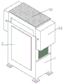
Fig. 1 is a schematic structural view of the present invention.
Fig. 2 is a schematic cross-sectional view of the body of the present invention.
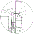
Fig. 3 is a schematic installation view of the heat dissipating fan of the present invention.
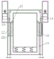
Fig. 4 is a schematic view of the installation of the lightweight partition panel of the present invention.
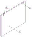
Fig. 5 is a schematic structural view of the light partition panel of the present invention.
Fig. 6 is an installation view of the hoist rope of the present invention.
FIG. 7 is a schematic view of a lightweight partition cylinder according to the present invention.
Fig. 8 is a schematic side sectional view of the collecting vessel of the present invention.
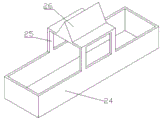
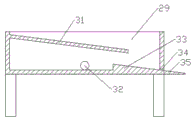
In the figure: 1. the main body, 2, supporting legs, 3, closing doors, 4, installation box, 5, installation cavity, 6, cooling box, 7, threaded pipe, 8, heat dissipation fan, 9, filtering part, 10, collecting part, 11, ventilation window, 12, partition plate, 13, short communication pipe, 14, long communication pipe, 15, ventilation pipe, 16, lower threading hole, 17, dust filtering net, 18, water filtering net, 19, chute, 20, light partition plate, 21, hoisting hole, 22, water storage tank, 23, fixed pulley, 24, light partition cylinder, 25, light support frame, 26, hollow triangle cylinder, 27, stirring paddle, 28, hinge cylinder, 29, collecting barrel, 30, filter plate, 31, guiding sloping plate, 32, drain pipe, 33, slope, 34, water outlet, 35, guiding plate, 36, hoisting rope, 37 and upper threading hole.
Detailed Description
The invention is described in further detail below with reference to the drawings and the specific examples.
As shown in fig. 1-8, a power distribution cabinet with high heat dissipation for electric power comprises a main body 1, supporting legs 2, a sealing door 3, a mounting box 4, a mounting cavity 5, a cooling box 6, threaded pipes 7, a heat dissipation fan 8, a filtering part 9 and a collecting part 10, wherein the four corners of the bottom end of the main body 1 are respectively fixed with a vertical supporting leg 2, the front part of the main body 1 is hinged with the vertical sealing door 3, a vertical mounting box 4 is fixed inside the main body 1, the mounting cavity 5 is formed between the main body 1 and the mounting box 4, a horizontal cooling box 6 is fixed at the bottom end of the mounting box 4, cooling liquid is filled inside the cooling box 6, a plurality of vertical threaded pipes 7 are fixed inside the cooling box 6, each threaded pipe 7 is used for communicating the inner cavity of the mounting box 4 with the mounting cavity 5, the top end of the mounting box 4 is fixed with a horizontal heat dissipation fan 8, the inside the mounting cavity 5 is provided with a filtering part 9, and the top end of the main body 1 is provided with a vertical collecting part 10.
The filtering part 9 comprises a ventilation window 11, a partition plate 12, a short communication pipe 13, a long communication pipe 14, a ventilation pipe 15, a lower threading hole 16, a dust filtering net 17, a water filtering net 18, a chute 19, a light partition plate 20 and a hoisting hole 21, wherein a vertical ventilation window 11 is respectively fixed at the left end and the right end of the main body 1, a horizontal partition plate 12 is respectively fixed at the left part and the right part of the installation cavity 5, a plurality of vertical short communication pipes 13 and a plurality of vertical long communication pipes 14 are symmetrically fixed at the top ends of the partition plate 12, a plurality of vertical ventilation pipes 15 are symmetrically fixed at the top ends of the partition plate 12, two vertical lower threading holes 16 are symmetrically penetrated at the top ends of the partition plate 12, each ventilation pipe 15 is communicated with the upper part and the lower part of the installation cavity 5, two vertical dust filtering nets 17 and vertical water filtering nets 18 are symmetrically fixed at the bottom ends of the two vertical chute 19 are symmetrically fixed at the left part and the right part of the installation cavity 5, a vertical light partition plate 20 is respectively slidingly connected in the chute 19 at the left part and the right part of the installation cavity 5, and two horizontal hoisting holes 21 are respectively penetrated at the upper part and lower part of the light partition plate 20.
The collecting part 10 comprises a water storage tank 22, fixed pulleys 23, light partition cylinders 24, light support frames 25, hollow triangular cylinders 26, stirring paddles 27, a winch 28, a collecting barrel 29, a filter plate 30, a guide inclined plate 31, drain pipes 32, a slope 33, a water outlet 34 and guide plates 35, wherein vertical water storage tanks 22 are respectively fixed at the left end and the right end of the main body 1, the water storage tanks 22 are respectively communicated with each short communicating pipe 13 and each long communicating pipe 14, two vertical fixed pulleys 23 are respectively fixed at the left end and the right end of the top end of the mounting cavity 5, a vertical light partition cylinder 24 is respectively connected inside the water storage tanks 22 in a sliding manner, a vertical light support frame 25 is respectively fixed at the top end of the light partition cylinder 24, a horizontal hollow triangular cylinder 26 is respectively fixed at the top end of the light support frames 25, a horizontal stirring paddle 27 is respectively connected at the middle part of the water storage tank 22 through bearings, a horizontal drum 28 is respectively fixed at the front and rear end of the two inclined plates 27, a vertical collecting barrel 29 is respectively fixed at the top end of the main body 1, a horizontal drain pipe 29 is respectively fixed at the rear end of the inclined plates 29 is fixedly connected with the front end of the water storage tank 29, a horizontal inclined plates 32 are respectively fixed at the rear end of the inclined plates 29, and the water storage tank 32 is respectively connected with the horizontal inclined plates 32.
The winch 28 is wound with a hoisting rope 36, the inner walls of the two water storage tanks 22 are respectively penetrated with two horizontal upper threading holes 37, each hoisting rope 36 is bound and connected with the hoisting holes 21 on the two light partition plates 20 after passing through the upper threading holes 37, the fixed pulleys 23 and the lower threading holes 16, and the two light partition plates 20 can be driven to slide up and down along the sliding grooves 19 by the hoisting ropes 36 after the stirring paddles 27 rotate.
The working principle of the invention is as follows: when the power supply of the heat radiation fan 8 is connected, the heat radiation fan 8 starts to rotate, so that the air at the upper part of the installation cavity 5 can be conveyed to the inner cavity of the installation box 4 and then conveyed to the bottom of the installation cavity 5 through the threaded pipe 7, in the process, the hot air in the installation cavity 4 returns to the bottom of the installation cavity 5 under the cooling of cooling liquid when passing through the threaded pipe 7, then returns to the inside of the installation box 4 through the filtration of the water filtering net 18, thereby achieving the purpose of circulating cooling, when the dust filtering net 17 and the water filtering net 18 are separated by the separating plate, the inner circulating cooling of the installation cavity 5 and the installation box 4 can be realized, when the dust filtering net 17 and the water filtering net 18 cannot be separated by the light separating plate 20, the outer circulating cooling of the outside and the installation cavity 5 and the installation box 4 can be realized, and when the rainfall begins to fall onto the guide inclined plate 31 through the filter plate 30, the accumulated dust is wrapped and discharged through the slope 33 and the water outlet 34, so that the effect of removing the accumulated dust is realized, the filter plate 30 can filter out small blocks of impurities such as leaves, stones and the like, the blockage of the water outlet 34 can be prevented, when the rainwater gradually increases, the accumulated dust flows over the slope 33 and falls onto the stirring paddles 27 along the water outlet pipe 32, the stirring paddles 27 rotate in opposite directions, the lifting ropes 36 are wound by the winch 28, the lifting of the light partition plate 20 is realized, the dust filter net 17 and the water filter net 18 are partitioned, the internal circulation cooling can be realized, the corrosion of external moisture to the moisture in the installation box 4 can be avoided, when the rainwater in the water storage box 22 begins to accumulate, the rainwater firstly flows out of the short communicating pipe 13, the dust filter net 17 is subjected to primary flushing, and then the rainwater is accumulated continuously, the hollow triangular cylinder 26 drives the light partition cylinder 24 to rise under the action of the buoyancy force, so that the short communicating pipe 13 is blocked, the rapid accumulation of the rainwater in the water storage tank 22 is realized, then the hollow triangular cylinder 26 rises to the bottom of the stirring paddle 27 along with the continuous accumulation of the rainwater, so that the rotation of the stirring paddle 27 can be limited, and the light partition plate 20 partitions the dust filtering net 17 and the water filtering net 18 at the moment, even if the rainfall stops at the moment, the reverse rotation of the stirring paddle 27 can not be caused, the phenomenon that the light partition plate 20 falls immediately after the lasting rainfall stops can not be caused, so that the moisture corrosion of the internal circuit of the installation tank 4 and electric appliances caused by the evaporation of the rainwater after the rainfall can be prevented, when the rainwater in the water storage tank 22 continues to accumulate, the rainwater can wash the dust filtering net 17 again through the long communicating pipe 14, so as to clean the dust filter net 17 and prevent the blockage thereof, while when rainfall stops, the rainwater in the water storage tank 22 begins to evaporate slowly, so that the hollow triangular cylinder 26 descends slowly, when the hollow triangular cylinder is completely separated from the stirring paddle 27, a certain time is required, and the stirring paddle 27 rotates reversely under the gravity action of the light partition plate 20, so as to convert the external circulation, and the evaporation period of the external rainwater can be skipped in the previous time period, so that the evaporation period of the external rainwater can be prevented, and the moisture corrosion of the internal circuit and the electric appliances of the installation tank 4 caused by the evaporation of the rainwater after rainfall can be prevented, and when the rainfall does not exist for a long time, the slow descent of the rainwater in the water storage tank 22 causes the slow descent of the light partition cylinder 24, so that the short communicating pipe 13 is communicated, and then the accumulated rainwater washes the dust filter net 17, so as to clean the dust filter net 17, thus, the clogging phenomenon of the dust filter net 17 caused by long-time uncleaned is prevented, and thus, a good heat dissipation effect is ensured.
The foregoing is a preferred embodiment of the present invention, and it will be apparent to those skilled in the art from this disclosure that changes, modifications, substitutions and alterations can be made without departing from the principles and spirit of the invention.
Claims (1)
1. The utility model provides a be used for high heat dissipation switch board of electric power, includes main part (1), supporting leg (2), closing door (3), install bin (4), installation cavity (5), cooling box (6), screwed pipe (7), heat dissipation fan (8), filtration portion (9), collection part (10), its characterized in that: the utility model discloses a dust filter, including main part (1), cooling tank (6), filter screen (19), filter screen (20), filter screen (11), partition plate (12), cooling tank (6) are inside to be filled with coolant liquid, cooling tank (6) are inside to be fixed with a plurality of vertical screwed pipes (7), each screwed pipe (7) are linked together with install box (4) inner chamber and install chamber (5), install box (4) top and be fixed with a horizontally radiator fan (8), install box (5 internally mounted has a filter part (9), install a vertically collecting part (10) on main part (1) top, filter part (9) include ventilation window (11), division plate (12), short (13), long (14), breather pipe (16), down through wires (16), filter screen (19), a left side filter screen (20) are fixed with two through holes (20) respectively, two parts respectively are fixed with a horizontally division board (12) about installation cavity (5), two division board (12) top symmetry is fixed with a plurality of vertically short communicating pipe (13) and a plurality of vertically long communicating pipe (14), two division board (12) top symmetry is fixed with a plurality of vertical breather pipe (15), two division board (12) top symmetry runs through and has two vertically down through wires hole (16), each breather pipe (15) are linked together two upper and lower parts of installation cavity (5), two division board (12) bottom symmetry is fixed with two vertically dust filter net (17) and vertical drainage net (18), two vertical spouts (19) are fixed with in two parts symmetry about installation cavity (5), each sliding connection has a vertically light partition board (20) in spout (19) of two parts about installation cavity (5), two light partition board (20) are last to be run through respectively to have two horizontally hoist and mount hole (21), collecting part (10) are including water tank (22), fixed pulley (23), light partition board (24), light weight (24), hollow prop (26), hollow prop (32), a guide drum (32), a three-way drum (30), a collection drum (32), a three-way drum (30) The utility model discloses a water-saving type water-saving device, which comprises a water outlet (34) and a guide plate (35), wherein a vertical water storage tank (22) is respectively fixed at the left end and the right end of a main body (1), the two water storage tanks (22) are respectively communicated with each short communicating pipe (13) and each long communicating pipe (14), two vertical fixed pulleys (23) are respectively fixed at the left end and the right end of the top end of a mounting cavity (5), a vertical light partition cylinder (24) is respectively and slidingly connected inside the water storage tank (22), a vertical light support frame (25) is respectively fixed at the top end of the light partition cylinder (24), a horizontal hollow triangular cylinder (26) is respectively fixed at the top end of the light support frame (25), a horizontal stirring paddle (27) is respectively and rotatably connected at the middle part of the water storage tank (22) through a bearing, a horizontal cylinder (28) is respectively fixed at the front part and the rear part of the stirring paddle (27), a vertical collecting cylinder (29) is fixed at the top end of the main body (1), a horizontal filter plate (30) is mounted at the top end of the collecting cylinder (29), a horizontal filter plate (30) is respectively fixed at the front end of the collecting cylinder (29), a horizontal drain pipe (32) is fixed at the front end of the collecting cylinder (29), the utility model discloses a light partition board, including collecting vessel (29), fixed pulley (23), lower through wires hole (16), collecting vessel (29) rear end is fixed with a horizontally outlet (34), collecting vessel (29) rear end is fixed with a horizontally deflector (35), two drain pipe (32) are linked together with two water storage tank (22) upper portions respectively, two twine respectively on winch (28) have a hoist and mount rope (36), two water storage tank (22) inner wall has two horizontally last through wires hole (37) respectively to run through, each hoist and mount rope (36) are binded with hoist and mount hole (21) on two light partition board (20) behind last through wires hole (37), fixed pulley (23) and lower through wires hole (16), two stir oar (27) and rotate the back and can drive two light partition board (20) and slide from top to bottom along each spout (19) through hoist and mount rope (36).
Priority Applications (1)
| Application Number | Priority Date | Filing Date | Title |
|---|---|---|---|
| CN202110133558.7A CN112670873B (en) | 2021-02-01 | 2021-02-01 | Be used for high heat dissipation switch board of electric power |
Applications Claiming Priority (1)
| Application Number | Priority Date | Filing Date | Title |
|---|---|---|---|
| CN202110133558.7A CN112670873B (en) | 2021-02-01 | 2021-02-01 | Be used for high heat dissipation switch board of electric power |
Publications (2)
| Publication Number | Publication Date |
|---|---|
| CN112670873A CN112670873A (en) | 2021-04-16 |
| CN112670873B true CN112670873B (en) | 2023-05-05 |
Family
ID=75414981
Family Applications (1)
| Application Number | Title | Priority Date | Filing Date |
|---|---|---|---|
| CN202110133558.7A Active CN112670873B (en) | 2021-02-01 | 2021-02-01 | Be used for high heat dissipation switch board of electric power |
Country Status (1)
| Country | Link |
|---|---|
| CN (1) | CN112670873B (en) |
Families Citing this family (5)
| Publication number | Priority date | Publication date | Assignee | Title |
|---|---|---|---|---|
| CN113422303B (en) * | 2021-07-21 | 2023-10-31 | 安徽得润电气技术有限公司 | Container transformer substation capable of automatically dehumidifying and cleaning filter screen in rainy days |
| CN113824028B (en) * | 2021-09-24 | 2023-08-18 | 山东国恒机电配套有限公司 | Intelligent energy-saving electrical cabinet for optimizing electric energy |
| CN113908666B (en) * | 2021-10-12 | 2024-03-22 | 衡阳市盛亚化工科技有限公司 | Chlorinated paraffin environmental protection production system |
| CN113782305B (en) * | 2021-11-11 | 2022-02-15 | 江苏新特变科技股份有限公司 | Energy-saving heat dissipation type outdoor dry-type transformer |
| CN117424089B (en) * | 2023-03-23 | 2024-04-26 | 昆山盛英电气有限公司 | Power distribution cabinet structure |
Citations (6)
| Publication number | Priority date | Publication date | Assignee | Title |
|---|---|---|---|---|
| JP2005098572A (en) * | 2003-09-24 | 2005-04-14 | Matsushita Electric Ind Co Ltd | Cooling device |
| CN106058652A (en) * | 2016-06-17 | 2016-10-26 | 国网山东省电力公司东明县供电公司 | Power distribution cabinet for humid and dusty outdoor environment |
| CN106329335A (en) * | 2016-11-14 | 2017-01-11 | 仲炳华 | Dustproof electric cabinet |
| CN207603052U (en) * | 2017-11-06 | 2018-07-10 | 山东安澜电力科技有限公司 | A kind of electric automatization power distribution cabinet |
| CN209571700U (en) * | 2019-02-23 | 2019-11-01 | 上海容贝实业有限公司 | A kind of hanging rain-proof control cabinet in open air |
| CN111884061A (en) * | 2020-09-01 | 2020-11-03 | 陈伟 | Waterproof type electric power cabinet |
-
2021
- 2021-02-01 CN CN202110133558.7A patent/CN112670873B/en active Active
Patent Citations (6)
| Publication number | Priority date | Publication date | Assignee | Title |
|---|---|---|---|---|
| JP2005098572A (en) * | 2003-09-24 | 2005-04-14 | Matsushita Electric Ind Co Ltd | Cooling device |
| CN106058652A (en) * | 2016-06-17 | 2016-10-26 | 国网山东省电力公司东明县供电公司 | Power distribution cabinet for humid and dusty outdoor environment |
| CN106329335A (en) * | 2016-11-14 | 2017-01-11 | 仲炳华 | Dustproof electric cabinet |
| CN207603052U (en) * | 2017-11-06 | 2018-07-10 | 山东安澜电力科技有限公司 | A kind of electric automatization power distribution cabinet |
| CN209571700U (en) * | 2019-02-23 | 2019-11-01 | 上海容贝实业有限公司 | A kind of hanging rain-proof control cabinet in open air |
| CN111884061A (en) * | 2020-09-01 | 2020-11-03 | 陈伟 | Waterproof type electric power cabinet |
Also Published As
| Publication number | Publication date |
|---|---|
| CN112670873A (en) | 2021-04-16 |
Similar Documents
| Publication | Publication Date | Title |
|---|---|---|
| CN112670873B (en) | Be used for high heat dissipation switch board of electric power | |
| CN207265481U (en) | A kind of water-proof type is taken out stitches production formula distribution box | |
| CN213068980U (en) | Outdoor rainproof and anti-creeping ammeter box | |
| CN216251879U (en) | Self-moving anti-seepage outdoor power distribution cabinet | |
| CN208797444U (en) | A kind of box-type substation of utilization of new energy resources | |
| CN104164892B (en) | A kind of cable tunnel multifunctional examining well | |
| CN111952848A (en) | Outdoor high-low voltage power distribution cabinet | |
| CN116073268A (en) | Preassembled transformer substation | |
| CN216290029U (en) | Cable branch box capable of preventing rainwater from entering | |
| CN215419000U (en) | Outdoor high-voltage board of rain-proof snow weather | |
| CN115714306A (en) | Dampproofing effectual electric power cabinet | |
| CN211184770U (en) | Waterproof and dustproof electricity saver | |
| CN215600794U (en) | Self-moving type anti-seepage outdoor power distribution cabinet | |
| CN214355578U (en) | Drainage system for electrical equipment and electrical equipment using drainage system | |
| CN114976954A (en) | Intelligent detection equipment based on multi-power-supply multi-connection framework of power distribution network | |
| CN112186529B (en) | Power distribution cabinet | |
| CN211790705U (en) | Outdoor cable distribution box with moisture-proof function | |
| CN208908684U (en) | A kind of green house of vegetables structure for the rainwater that converges | |
| CN216530149U (en) | Block terminal that radiating effect is good | |
| CN212114322U (en) | Switch board for construction site | |
| CN212810940U (en) | Outdoor power cabinet | |
| CN219181117U (en) | Cable branch box with protection function | |
| CN220368307U (en) | Waterproof power distribution cabinet | |
| CN219304209U (en) | Waterproof sealing structure of power distribution cabinet | |
| CN211526544U (en) | Heat conduction air port for geothermal heating |
Legal Events
| Date | Code | Title | Description |
|---|---|---|---|
| PB01 | Publication | ||
| PB01 | Publication | ||
| SE01 | Entry into force of request for substantive examination | ||
| SE01 | Entry into force of request for substantive examination | ||
| TA01 | Transfer of patent application right |
Effective date of registration: 20230410 Address after: 515065 In front of Tiezhou Neighborhood Committee, Yuzhou Road, Longhu District, Shantou City, Guangdong Province Applicant after: Guangdong yuanshengda Electrical Appliance Co.,Ltd. Address before: Henan University of science and technology, 263 Kaiyuan Avenue, Luolong District, Luoyang City, Henan Province Applicant before: Zheng Jiji |
|
| TA01 | Transfer of patent application right | ||
| GR01 | Patent grant | ||
| GR01 | Patent grant |