CN112652500A - Load switch-fuse combined electrical apparatus - Google Patents
Load switch-fuse combined electrical apparatus Download PDFInfo
- Publication number
- CN112652500A CN112652500A CN201910969984.7A CN201910969984A CN112652500A CN 112652500 A CN112652500 A CN 112652500A CN 201910969984 A CN201910969984 A CN 201910969984A CN 112652500 A CN112652500 A CN 112652500A
- Authority
- CN
- China
- Prior art keywords
- tripping
- switch
- load switch
- fuse
- control switch
- Prior art date
- Legal status (The legal status is an assumption and is not a legal conclusion. Google has not performed a legal analysis and makes no representation as to the accuracy of the status listed.)
- Pending
Links
Images




Classifications
-
- H—ELECTRICITY
- H01—ELECTRIC ELEMENTS
- H01H—ELECTRIC SWITCHES; RELAYS; SELECTORS; EMERGENCY PROTECTIVE DEVICES
- H01H31/00—Air-break switches for high tension without arc-extinguishing or arc-preventing means
- H01H31/02—Details
- H01H31/12—Adaptation for built-in fuse
-
- H—ELECTRICITY
- H01—ELECTRIC ELEMENTS
- H01H—ELECTRIC SWITCHES; RELAYS; SELECTORS; EMERGENCY PROTECTIVE DEVICES
- H01H3/00—Mechanisms for operating contacts
- H01H3/22—Power arrangements internal to the switch for operating the driving mechanism
- H01H3/30—Power arrangements internal to the switch for operating the driving mechanism using spring motor
- H01H3/3005—Charging means
-
- H—ELECTRICITY
- H01—ELECTRIC ELEMENTS
- H01H—ELECTRIC SWITCHES; RELAYS; SELECTORS; EMERGENCY PROTECTIVE DEVICES
- H01H3/00—Mechanisms for operating contacts
- H01H3/22—Power arrangements internal to the switch for operating the driving mechanism
- H01H3/30—Power arrangements internal to the switch for operating the driving mechanism using spring motor
- H01H3/3047—Power arrangements internal to the switch for operating the driving mechanism using spring motor adapted for operation of a three-position switch, e.g. on-off-earth
Landscapes
- Driving Mechanisms And Operating Circuits Of Arc-Extinguishing High-Tension Switches (AREA)
Abstract
The invention relates to the technical field of high-voltage electrical equipment, in particular to a load switch-fuse combined electrical apparatus. The load switch-fuse combination comprises: a fixed mount; a load switch; the spring operating mechanism is used for controlling the opening and closing operations of the load switch and comprises an energy storage motor for driving a closing spring to store energy; a fuse; the mechanical tripping mechanism is arranged between the fuse and the load switch and drives the spring operating mechanism to open when an ejector pin of the fuse is ejected out; the combined electrical apparatus still includes: the control switch is used for controlling the power supply line where the energy storage motor is located to be disconnected; the trigger piece is arranged opposite to the control switch; one of the control switch and the trigger piece is arranged on the mechanical tripping mechanism, the other one is arranged on the fixed frame, and when the mechanical tripping mechanism controls the load switch to be switched off, the trigger piece is driven to act relative to the control switch so as to trigger the control switch and disconnect a power supply circuit where the energy storage motor is located.
Description
Technical Field
The invention relates to the technical field of high-voltage electrical equipment, in particular to a load switch-fuse combined electrical apparatus.
Background
The safety and reliability of equipment in a power system have high requirements, so that the interlocking device is widely applied to the fields of machinery, electricity and the like. The load switch-fuse combined electrical appliance is a combined switch device which is controlled by a load switch and is fused and protected by a fuse. When short-circuit current occurs, the fuse can drive the load switch to be tripped so as to enable the load switch to be switched off, and particularly as shown in the patent of the Chinese utility model with the publication number of CN206179757U, the utility model discloses a load switch-fuse combined electrical apparatus, wherein the combined electrical apparatus comprises a fixing frame, a switching-on/off unit (namely, a load switch), an isolating switch, a grounding switch and a fuse, the load switch and the fuse are connected in series, and the spring operating mechanism further comprises a spring operating mechanism, and the spring operating mechanism drives the load switch to be switched on/off. Meanwhile, the mechanical tripping mechanism is arranged and specifically comprises a push plate arranged at the thimble of the fuse, and the push plate is in transmission connection with a tripping half shaft (namely a brake separating half shaft) of the spring operating mechanism through a series of link mechanisms. When the short-circuit protection switch is used, when short-circuit current occurs, the thimble of the fuse collides with the push plate, the push plate drives the tripping half shaft to rotate after a series of transmissions, and the tripping spring is released to drive the load switch to trip.
The load switch-fuse combined electrical apparatus in the prior art can drive the load switch to trip and open when short-circuit current occurs, and control the power transmission line to be disconnected. However, as is known, after a spring operating mechanism of the load switch is opened, the motor automatically drives the energy storage spring to store energy, and after receiving a closing signal, the energy storage spring is released to drive a moving contact of the load switch to be connected with a stationary contact of the load switch, so as to place the load switch at a closing position. The problem that produces from this lies in, after taking place short-circuit current, the fuse drives load switch dropout separating brake, but, the motor can make energy storage spring energy storage again after the separating brake, has the risk that energy storage spring drove load switch combined floodgate again, causes the threat to operating personnel's personal safety, and the electric transmission line secondary combined floodgate also produces the influence to the electrical apparatus on the electric transmission line easily simultaneously.
Disclosure of Invention
The invention aims to provide a load switch-fuse combined electrical appliance, which aims to solve the technical problem that in the prior art, after a load switch is switched off, the risk of reclosing exists, and the personal safety of an operator is threatened.
In order to achieve the purpose, the technical scheme of the load switch-fuse combined electrical appliance is as follows: a load switch-fuse combination comprising:
a fixed mount;
a load switch;
the spring operating mechanism is used for controlling the opening and closing operations of the load switch and comprises an energy storage motor for driving a closing spring to store energy;
a fuse;
the mechanical tripping mechanism is arranged between the fuse and the load switch and drives the spring operating mechanism to open when an ejector pin of the fuse is ejected out;
the combined electrical apparatus still includes:
the control switch is used for controlling the power supply line where the energy storage motor is located to be disconnected;
the trigger piece is arranged opposite to the control switch;
one of the control switch and the trigger piece is arranged on the mechanical tripping mechanism, the other one of the control switch and the trigger piece is arranged on the fixed frame, and when the mechanical tripping mechanism controls the load switch to be switched off, the trigger piece acts relative to the control switch to trigger the control switch and disconnect a power supply circuit where the energy storage motor is located.
The invention has the beneficial effects that: through setting up control switch and trigger, can control the disconnection of power supply line that energy storage motor belongs to when mechanical tripping device control load switch separating brake, prevent that energy storage motor from driving the combined floodgate spring energy storage once more, and then avoid appearing the produced risk of combined electrical apparatus combined floodgate once more, improve combined electrical apparatus's safety in utilization, effectively protect the electrical apparatus on the transmission line. In addition, the trigger part is arranged on the mechanical tripping mechanism, a power source and a transmission mechanism are not required to be additionally arranged to drive the trigger part to move, the original mechanism is utilized to realize a new function, the cost is lower, and the structure is simpler.
Furthermore, the spring operating mechanism is provided with a tripping half shaft, the mechanical tripping mechanism comprises a tripping connecting shaft arranged on one side of the tripping half shaft, the tripping connecting shaft is rotatably arranged on the fixing frame, one end of the tripping connecting shaft is connected with the tripping half shaft through a tripping connecting rod, the tripping connecting shaft can be pushed by a thimble of the fuse to rotate, the trigger is fixed at one end of the tripping connecting shaft where the tripping connecting rod is located, and the control switch is fixed at a position, corresponding to the trigger, on the fixing frame. The tripping connecting rod and the triggering piece are arranged on the same side of the tripping connecting shaft, so that the space can be saved.
Furthermore, the end part of the end of the tripping connecting shaft is provided with a screw hole, and the trigger piece is connected in the screw hole of the tripping connecting shaft. The trigger piece is installed in a threaded connection mode, and installation is convenient.
Furthermore, control switch is mechanical trigger formula control switch, and control switch's trigger point arranges in control switch's perpendicular to dropout connecting axle axis one side, the trigger is L shape plate body, and one of them side of L shape plate body links to each other with the dropout connecting axle, and the another side is on a parallel with dropout connecting axle axis and is used for roof pressure control switch's trigger point. One side of the trigger piece is parallel to the axis of the tripping connecting shaft and can be in top pressure contact with a trigger point vertical to the axis of the tripping connecting shaft better.
Furthermore, the control switch is detachably arranged on the fixed frame through a control switch fixing plate. The control switch can be detachably connected, so that the position can be conveniently replaced and adjusted.
Furthermore, the control switch is connected in series in a power supply line of the energy storage motor.
Furthermore, the combined electrical apparatus comprises a three-phase load switch, a load switch rotating shaft which drives the three-phase load switch to act simultaneously, a three-phase grounding switch and a grounding switch rotating shaft which drives the three-phase grounding switch to act simultaneously, and the mechanical tripping mechanism is arranged at one end of the fuse where the grounding switch rotating shaft is located. In the both ends of fuse, the spare part of load switch place one end is more, and the space of staying is less, and the spare part of earthing switch place one end is less, and the space of staying is great, arranges mechanical tripping device in earthing switch place one end, can utilize the space better, and it is also more convenient to arrange.
Furthermore, the spring operating mechanism is provided with a tripping half shaft, the mechanical tripping mechanism comprises a tripping connecting shaft arranged on one side of the tripping half shaft, the tripping half shaft and the tripping connecting shaft extend in parallel, the tripping connecting shaft is rotatably arranged on the fixing frame, one end of the tripping connecting shaft is connected with the tripping half shaft through a tripping connecting rod, the tripping connecting shaft can be pushed by a thimble of the fuse to rotate, the mechanical tripping mechanism further comprises a torsional spring used for resetting the tripping connecting shaft and the tripping connecting rod, the torsional spring is sleeved on the tripping connecting shaft, and two ends of the torsional spring are respectively pressed on the tripping connecting shaft and the fixing frame. After the torsion spring is arranged, the automatic reset can be realized after parts are replaced, manual operation is not needed, and the operation is more convenient.
Furthermore, the mechanical tripping mechanism comprises a tripping connecting plate sleeved on the tripping half shaft in a rotation stopping manner, the tripping connecting plate is an L-shaped piece, one edge of the tripping connecting plate is used for being connected with a tripping connecting rod, a long hole for the tripping connecting rod to penetrate through is formed in the edge of the tripping connecting plate, the tripping connecting rod penetrates through the edge of the tripping connecting plate, and the end part of the tripping connecting plate is provided with a brake separating pushing piece used for pushing the tripping connecting plate to perform brake separating operation. The tripping connecting rod penetrates through the tripping connecting plate, and the long hole in the tripping connecting plate plays a role in guiding the tripping connecting rod.
Furthermore, a limit stop piece is also arranged on the other side of the corresponding side of the tripping connecting plate on the tripping connecting rod, and a space is reserved between the separating brake pushing piece and the limit stop piece, so that the tripping connecting plate and the tripping connecting rod can move relatively. After the limiting and stopping piece is arranged, the tripping connecting plate can be prevented from being separated from the tripping connecting rod when rotating along with the tripping half shaft in normal use, and meanwhile, the tripping half shaft can be prevented from driving the mechanical tripping mechanism to act, so that the control switch is triggered.
Drawings
FIG. 1 is a schematic diagram of an embodiment of the load switch-fuse combination of the present invention;
FIG. 2 is an enlarged view taken at A in FIG. 1;
FIG. 3 is a schematic diagram of the mechanical trip mechanism and trip half shaft of the load switch-fuse combination electrical apparatus embodiment of the present invention;
FIG. 4 is a schematic diagram of a mechanical trip mechanism (no trip link shown) for an embodiment of the load switch-fuse combination of the present invention;
FIG. 5 is an enlarged view at B in FIG. 4;
FIG. 6 is an assembled schematic view of the trip half shaft and trip link plate of FIG. 3;
FIG. 7 is an assembled schematic view of the trip half shaft, trip link plate, and trip link of FIG. 3;
fig. 8 is a schematic view of the trip paddle component of fig. 3;
FIG. 9 is a schematic diagram of the fuse and trip paddle components of an embodiment of the load switch-fuse combination of the present invention;
description of reference numerals: 1-a fixed mount; 2-a grounding switch; 3-a mechanical tripping mechanism; 4-a fuse; 5-a load switch; 6-load switch rotating shaft; 7-an isolating switch; 8-a spring operating mechanism; 9-a grounding switch rotating shaft; 10-a trip pusher plate member; 11-an insulating link; 12-tripping connecting shaft; 13-trip link; 14-trip half shaft; 15-tripping half shaft sleeve; 16-tripping half-shaft torsion spring; 17-a brake separating plate; 18-trip link plate; 19-tripping the connecting shaft sleeve; 20-tripping connecting rod crank arm; 21-tripping connecting shaft torsion spring; 22-trip push plate mounting plate; 23-tripping push plate; 24-a pin shaft; 25-insulating connecting rod crank arm; 26-magnetic blow switch press plate; 27-a magnetic blow switch mounting plate; 28-magnetic blow switch; 29-a first nut; 30-a second nut; 31-melting card; 32-ejector pins; and 33, tripping a connecting shaft crank arm.
Detailed Description
The following further describes embodiments of the present invention with reference to the drawings.
The load switch-fuse combined electrical apparatus can realize mechanical and electrical double interlocking, when the power transmission line has abnormal conditions such as short-circuit current and the like, the thimble of the fuse stretches out, the load switch is arranged at the position of the opening, and simultaneously, the energy storage motor of the spring operating mechanism can be disconnected, so that the secondary energy storage closing is prevented.
One embodiment of the load switch-fuse combination is shown in fig. 1 to 9, and hereinafter referred to as a load switch-fuse combination as a combination.
As shown in fig. 1, the combined electrical apparatus includes a fixing frame 1, a three-phase load switch 5, a three-phase grounding switch 2 and a three-phase isolating switch 7 are installed on the fixing frame 1, and an operating mechanism is correspondingly arranged, the operating mechanism includes a grounding switch operating mechanism for controlling the switching on and off of the grounding switch 2, the grounding switch operating mechanism includes a grounding switch rotating shaft 9, and the switching on and off of the three-phase grounding switch 2 is controlled through the grounding switch rotating shaft 9. The operating mechanism also comprises an isolating switch operating mechanism for controlling the three-phase isolating switch 7 to be switched on and switched off. The operating mechanism further comprises a spring operating mechanism 8 for controlling the three-phase load switch 5 to be switched on and switched off, the spring operating mechanism 8 comprises a load switch rotating shaft 6, and the three-phase load switch is controlled to be switched on and switched off through the load switch rotating shaft 6. The combined electrical apparatus also comprises a three-phase fuse 4, the fuse 4 is connected with a load switch 5 in series, and the other end of the fuse 4 is used for outgoing lines. As can be seen from fig. 1, the load switch rotary shaft 6 and the ground switch rotary shaft 9 extend in parallel. The above contents are contents in the prior art, and are not described herein again.
In order to ensure that the load switch 5 can be rapidly opened after the fuse 4 is fused, the invention designs mechanical tripping and electrical interlocking. As shown in fig. 3 and 4, the mechanical trip mechanism 3 includes a trip push plate member 10 rotatably mounted on the fixing frame 1 and a trip connecting shaft 12, the trip push plate member 10 and the trip connecting shaft 12 are connected through an insulating connecting rod 11, and a trip connecting rod 13 is connected to the trip connecting shaft 12. When the tripping push plate component 10 is assembled and used, the tripping push plate component corresponds to the fuse 4, and the tripping connecting rod 13 is connected with the tripping half shaft 14.
As shown in fig. 6 and 7, how the trip link 13 is connected to the trip half shaft 14, the trip half shaft 14 is provided with a tripping plate 17, the tripping plate 17 is used for being pushed by a manual button or an electromagnet, and during normal operation, the tripping plate 17 drives the trip half shaft 14 to perform tripping operation. The tripping half shaft 14 is mounted on the fixing frame 1 through a tripping half shaft sleeve 15, and meanwhile, a tripping half shaft torsion spring 16 is arranged between the tripping half shaft 14 and the fixing frame 1, so that the automatic reset of the tripping half shaft 14 is realized. The mechanical trip mechanism 3 includes a trip link plate 18 fixedly mounted on the other end of the trip half shaft 14, and as can be seen from fig. 6 and 7, the trip link plate 18 is an L-shaped plate and has two sides, one of which is fixedly mounted on the trip half shaft 14, and the other of which is provided with a long hole for the trip link 13 to pass through. As shown in fig. 7, the trip link 13 penetrates one side of the trip half shaft 14, and a first nut 29 and a second nut 30 are fixed to the trip link 13, and the first nut 29 and the second nut 30 are located on both sides of one side of the trip link plate 18. As can be seen from fig. 7, the first nut 29 and the second nut 30 are two nuts, one is a stop nut, and the other is a back nut. A greater distance between the first nut 29 and the second nut 30 enables the trip link 13 to move relative to the trip link plate 18.
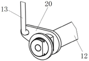
The connection mode of the tripping connecting rod 13 and the tripping connecting shaft 12 is shown in fig. 5, a tripping connecting rod crank arm 20 is fixedly sleeved on the tripping connecting shaft 12, and the tripping connecting rod 13 is hinged on the end part of the tripping connecting rod crank arm 20.
The structure of the trip push plate component 10 and the position relation with the fuse 4 are shown in fig. 8 and 9, the trip push plate component 10 includes a trip push plate mounting plate 22, the trip push plate mounting plate 22 is mounted on the fixing frame 1 by means of bolt connection, the trip push plate mounting plate 22 has two parallel support arms, a pin shaft 24 is rotatably mounted in the two support arms, a trip push plate 23 and an insulating connecting rod crank arm 25 are respectively fixed on the pin shaft 24, as shown in fig. 3 and 4, the insulating connecting rod crank arm 25 is hinged with one end of the insulating connecting rod 11 during assembly, the other end of the insulating connecting rod 11 is hinged with a trip connecting shaft crank arm 33, and the trip connecting shaft crank arm 33 is fixed on the trip connecting shaft 12. As shown in fig. 9, after the installation, the trip push plate 23 corresponds to the ejector pin 32 of the fuse 4, and the fuse 4 is fixed to the load switch 5 by the fuse clip 31. When the fuse 4 is fused, the thimble 32 pushes the trip push plate 23 to swing.
After the parts of the combined electrical apparatus are replaced, the combined electrical apparatus can be normally used, and in order to reset the mechanical tripping mechanism 3, as shown in fig. 4, a tripping connecting shaft torsion spring 21 is sleeved on the tripping connecting shaft 12, and the other end of the tripping connecting shaft torsion spring 21 is respectively abutted against or fixed on the tripping connecting shaft 12 and the fixing frame 1. The other end of the tripping connecting shaft 12 is sleeved with a tripping connecting shaft sleeve 19, and the tripping connecting shaft sleeve 19 is rotatably arranged on the fixed frame 1.
The mechanical tripping mechanism 3 of the invention is used as follows: when the load switch 5 is normally switched on and off, the thimble 32 retracts, and the tripping half shaft 14 in the spring operating mechanism 8 of the load switch 5 is normally rotated to trip. When short-circuit current occurs to the power transmission line, the fuse 4 is fused and the ejector pin 32 is ejected out, the ejector pin 32 pushes the tripping push plate 23 to rotate, the tripping push plate 23 drives the insulating connecting rod connecting lever 25 to swing through the pin shaft 24, the insulating connecting rod connecting lever 25 drives the insulating connecting rod 11 to translate, the insulating connecting rod 11 drives the tripping connecting shaft 12 to rotate through the tripping connecting shaft connecting lever 33, the tripping connecting shaft 12 rotates to drive the tripping connecting rod 13 to move towards the direction of the tripping half shaft 14, the first nut 29 on the tripping connecting rod 13 pushes the tripping connecting plate 18, and the tripping connecting plate 18 drives the tripping half shaft 14 to rotate, so that brake opening is realized. And the trip connecting shaft torsion spring 21 and the trip half shaft torsion spring 16 can reset the components.
In the present invention, an electrical interlock portion is arranged in addition to the mechanical trip mechanism 3. As shown in fig. 2, a magnetic blow switch 28 is mounted on the fixed frame 1, and the magnetic blow switch 28 is fixedly mounted on the fixed frame 1 through a magnetic blow switch mounting plate 27. As can be seen from fig. 1 and 6, in practice, the blow-switch 28 and the trip link plate 18 are disposed on both sides of the holder 1, and the blow-switch 28 is disposed at the same height as the trip connecting shaft 12. The magnetic blow-out switch 28 is a normally closed switch and is connected in series in the power supply line of the energy storage motor, and during normal use, the magnetic blow-out switch 28 can be considered as a passage, so that the power supply line is not affected. The magnetic blow switch 28 has an elastic contact which is located on one side of the tripping connecting shaft 12, and in order to ensure that the load switch 5 can control the power supply line of the energy storage motor to be disconnected after switching off and prevent the closing spring from storing energy again, a magnetic blow switch pressing plate 26 is installed at one end of the tripping connecting shaft 12. A threaded hole is formed in one end of the tripping connecting shaft 12, and the magnetic blow-out switch pressing plate 26 is fixed on the tripping connecting shaft 12 by screws. As shown in fig. 2, in order to better trigger the elastic contacts of the push-pull switch 28, the push-pull switch pressing plate 26 is designed as an L-shaped plate, wherein one side of the L-shaped plate is fixed on the trip connecting shaft 12, and the other side of the L-shaped plate extends along the arrangement direction of the plurality of elastic contacts, so that the plurality of elastic contacts can be triggered simultaneously.
The use of the mechanical trip mechanism 3 has been described above, and the trip connecting shaft torsion spring 21 is capable of holding the magnetic blow switch pressure plate 26 in a state of being separated from the magnetic blow switch 28 in normal use. The tripping connecting shaft 12 drives the tripping connecting rod 13 to act, and simultaneously drives the magnetic blow switch pressing plate 26 to rotate, and the magnetic blow switch 28 is pressed, so that the magnetic blow switch 28 controls the power supply line of the energy storage motor to be disconnected, the energy storage motor is prevented from driving the closing spring to store energy again, and the condition of secondary closing is avoided. At the same time, the trip link shaft torsion spring 21 can bring the blow switch pressure plate 26 to disengage the blow switch 28 again.
In this embodiment, the first nut 29 is used to push the trip link plate 18 to form a trip pushing member, the second nut 30 is used to prevent the trip link plate 18 from being pulled out from the trip link rod 13 to form a limit stop member, a certain distance is provided between the trip pushing member and the limit stop member to prevent the trip link plate 18 from being clamped, and meanwhile, the trip half shaft 14 is prevented from driving the mechanical trip mechanism to operate during normal switching on and off operations, so as to trigger the magnetic blow switch 28. In other embodiments, the structures of the separating brake pushing member and the limiting and stopping member may be changed according to actual conditions, for example, a fixing block fixed on the tripping connecting rod may be adopted.
In this embodiment, the mechanical tripping mechanism is integrally disposed at the side where the grounding switch is located, and in other embodiments, the mechanical tripping mechanism may be disposed at the side where the load switch is located.
In this embodiment, the magnetic blow-out switch pressing plate 26 actually constitutes a trigger for triggering the magnetic blow-out switch 28 to be turned off, and the magnetic blow-out switch pressing plate 26 is an L-shaped plate body, so that one side of the L-shaped plate body can be better utilized to press and trigger the magnetic blow-out switch.
In this embodiment, the magnetic blow switch 28 is connected in series in the power supply line of the energy storage motor, the magnetic blow switch 28 is a normally closed switch, and the magnetic blow switch 28 is triggered to disconnect the power supply line, and essentially, the magnetic blow switch 28 is a control switch, and the control switch is not necessarily connected in series in the power supply line of the energy storage motor, and may also control the power supply line to disconnect by controlling an existing switch in the power supply line, for example, when the control switch is triggered, a signal is sent to a switch on the power supply line or the energy storage motor, so as to disconnect the power supply line. The control switch can be a common travel switch without magnetic blow function or a common mechanical trigger switch. Or, in practice, the control switch may also be a non-contact switch, for example, the control switch is designed as a proximity switch, when the member to be triggered approaches the proximity switch, the proximity switch is triggered to send a signal of disconnection to the power supply line, and at this time, the form of the trigger depends on the type of the control switch.
Of course, in the above embodiments, the control switch is disposed on the fixing frame, and the trigger is disposed on the mechanical tripping mechanism, in other embodiments, the positions of the two may be interchanged.
In the embodiment, the screw hole is formed in the tripping connecting shaft, the trigger piece is installed in the screw hole, the structure is simpler, in other embodiments, the trigger piece can be integrally sleeved on the tripping connecting shaft, and the trigger piece is installed in a mode similar to a crank arm.
In other embodiments, the installation position of the trigger on the tripping connecting shaft can be changed according to actual conditions, and after the position of the trigger is changed, the control switch is changed accordingly.
In this embodiment, the trigger is mounted on the trip connecting shaft, and in other embodiments, one of the trigger and the control switch may be mounted on the trip connecting rod, or the position of the other of the trigger and the control switch may be changed along with the position of the trip push plate member. Namely, one of the trigger piece and the control switch is arranged on the mechanical tripping mechanism, and the position is not limited as long as the requirements of insulation and installation are met.
It should be noted that the overall concept of the present invention is that the mechanical tripping mechanism and the electrical control energy storage motor cannot rotate, and based on the concept, the specific structural form of the mechanical tripping mechanism can be changed according to the actual situation, for example, the mechanical tripping mechanism in the background art is adopted.
Claims (10)
1. A load switch-fuse combination comprising:
a fixed mount;
a load switch;
the spring operating mechanism is used for controlling the opening and closing operations of the load switch and comprises an energy storage motor for driving a closing spring to store energy;
a fuse;
the mechanical tripping mechanism is arranged between the fuse and the load switch and drives the spring operating mechanism to open when an ejector pin of the fuse is ejected out;
the method is characterized in that: the combined electrical apparatus still includes:
the control switch is used for controlling the power supply line where the energy storage motor is located to be disconnected;
the trigger piece is arranged opposite to the control switch;
one of the control switch and the trigger piece is arranged on the mechanical tripping mechanism, the other one of the control switch and the trigger piece is arranged on the fixed frame, and when the mechanical tripping mechanism controls the load switch to be switched off, the trigger piece acts relative to the control switch to trigger the control switch and disconnect a power supply circuit where the energy storage motor is located.
2. The load switch-fuse combination of claim 1, wherein: the spring operating mechanism is provided with a tripping half shaft, the mechanical tripping mechanism comprises a tripping connecting shaft arranged on one side of the tripping half shaft, the tripping connecting shaft is rotatably arranged on the fixing frame, one end of the tripping connecting shaft is connected with the tripping half shaft through a tripping connecting rod, the tripping connecting shaft can be pushed by a thimble of the fuse to rotate, the trigger is fixed at one end of the tripping connecting shaft where the tripping connecting rod is located, and the control switch is fixed at a position, corresponding to the trigger, on the fixing frame.
3. The load switch-fuse combination of claim 2, wherein: the end part of the end of the tripping connecting shaft is provided with a screw hole, and the trigger piece is connected in the screw hole of the tripping connecting shaft.
4. The load switch-fuse combination of claim 3, wherein: the control switch is a mechanical trigger type control switch, the trigger point of the control switch is arranged on one side of the control switch, which is perpendicular to the axis of the tripping connecting shaft, the trigger piece is an L-shaped plate body, one side of the L-shaped plate body is connected with the tripping connecting shaft, and the other side of the L-shaped plate body is parallel to the axis of the tripping connecting shaft and is used for jacking the trigger point of the control switch.
5. A load switch-fuse combination according to any one of claims 2-4, wherein: the control switch is detachably arranged on the fixed frame through the control switch fixing plate.
6. A load switch-fuse combination according to any one of claims 1-4, wherein: and the control switch is connected in series in a power supply line of the energy storage motor.
7. A load switch-fuse combination according to any one of claims 1-4, wherein: the combined electrical apparatus comprises a three-phase load switch, a load switch rotating shaft, a three-phase grounding switch and a grounding switch rotating shaft, wherein the load switch rotating shaft simultaneously drives the three-phase load switch to act, the grounding switch rotating shaft simultaneously drives the three-phase grounding switch to act, and a mechanical tripping mechanism is arranged at one end of the fuse where the grounding switch rotating shaft is located.
8. The load switch-fuse combination of claim 1, wherein: the mechanical tripping mechanism also comprises a torsional spring used for resetting the tripping connecting shaft and the tripping connecting rod, the torsional spring is sleeved on the tripping connecting shaft, and two ends of the torsional spring are respectively propped against the tripping connecting shaft and the fixing frame.
9. The load switch-fuse combination of claim 8, wherein: the mechanical tripping mechanism comprises a tripping connecting plate sleeved on a tripping half shaft in a rotation stopping manner, the tripping connecting plate is an L-shaped piece, one edge of the tripping connecting plate is used for being connected with a tripping connecting rod, a long hole for the tripping connecting rod to penetrate through is formed in the edge of the tripping connecting plate, the tripping connecting rod penetrates through the edge of the tripping connecting plate, and the end part of the tripping connecting plate is provided with a tripping pushing piece used for pushing the tripping connecting plate to perform tripping operation.
10. The load switch-fuse combination of claim 9, wherein: the other side of the corresponding side of the tripping connecting plate on the tripping connecting rod is also provided with a limiting and stopping piece, and a space is reserved between the separating brake pushing piece and the limiting and stopping piece, so that the tripping connecting plate and the tripping connecting rod can move relatively.
Priority Applications (1)
| Application Number | Priority Date | Filing Date | Title |
|---|---|---|---|
| CN201910969984.7A CN112652500A (en) | 2019-10-12 | 2019-10-12 | Load switch-fuse combined electrical apparatus |
Applications Claiming Priority (1)
| Application Number | Priority Date | Filing Date | Title |
|---|---|---|---|
| CN201910969984.7A CN112652500A (en) | 2019-10-12 | 2019-10-12 | Load switch-fuse combined electrical apparatus |
Publications (1)
| Publication Number | Publication Date |
|---|---|
| CN112652500A true CN112652500A (en) | 2021-04-13 |
Family
ID=75343058
Family Applications (1)
| Application Number | Title | Priority Date | Filing Date |
|---|---|---|---|
| CN201910969984.7A Pending CN112652500A (en) | 2019-10-12 | 2019-10-12 | Load switch-fuse combined electrical apparatus |
Country Status (1)
| Country | Link |
|---|---|
| CN (1) | CN112652500A (en) |
-
2019
- 2019-10-12 CN CN201910969984.7A patent/CN112652500A/en active Pending
Similar Documents
| Publication | Publication Date | Title |
|---|---|---|
| CN210778385U (en) | Load switch-fuse combined electrical apparatus | |
| CN112652500A (en) | Load switch-fuse combined electrical apparatus | |
| KR100730036B1 (en) | Load breake switch | |
| CN107578937A (en) | A kind of high-voltage combined electrical apparatus disconnecting switch and breaker interlocking mechanism | |
| KR101922156B1 (en) | Ground switch for distributing board | |
| CN210865978U (en) | Interlocking device of circuit breaker mechanism and three-station operating mechanism | |
| CN202633146U (en) | Fixed high-voltage switch cabinet interlocking mechanism | |
| CN210073696U (en) | High-voltage isolating switch | |
| KR20090055981A (en) | Circuit breaker for gas insulated switchgear | |
| CN106252167B (en) | A kind of novel ZW32 breakers inrush control device | |
| CN104900442A (en) | Lightning arrester-combined grounding switch and method thereof | |
| KR200283349Y1 (en) | Manually operated switch prevention means of gas insulated switchgear | |
| CN204167155U (en) | A kind of switch cubicle with interlock | |
| KR101869720B1 (en) | Gas insulated switchgear | |
| CN217182123U (en) | Opening operation mechanism of circuit breaker and circuit breaker | |
| CN210443486U (en) | Cabinet door linkage device with grounding switch keeping closing state | |
| CN216980480U (en) | Vehicle-mounted direct current circuit breaker with indirect tripping function | |
| CN215417983U (en) | Modular isolator fuse group | |
| CN220796616U (en) | Micro-breaker and auxiliary contact linkage mechanism | |
| CN215009272U (en) | General type quick arc extinguisher that can move open | |
| CN212322935U (en) | Take manual separating brake mechanism feed combination switch | |
| CN215869239U (en) | Circuit breaker tripping structure | |
| CN219759495U (en) | Anti-collision intelligent spring-operated circuit breaker | |
| CN217768157U (en) | Breaker closing position interlocking structure | |
| CN220691916U (en) | Isolating switch operating mechanism |
Legal Events
| Date | Code | Title | Description |
|---|---|---|---|
| PB01 | Publication | ||
| PB01 | Publication | ||
| SE01 | Entry into force of request for substantive examination | ||
| SE01 | Entry into force of request for substantive examination |