System for producing silane, monochlorosilane, dichlorosilane and hexachlorodisilane
Technical Field
The invention relates to the technical field of chemical synthesis, in particular to a system for producing silane, monochlorosilane, dichlorosilane and hexachlorodisilane
Background
The silane is mainly used for preparing super or ultra large scale integrated circuits, chips, flat panel displays, amorphous silicon thin film solar cells, high purity polysilicon growth, silicon nitride, silicon carbide micro powder and the like. There are three major processes for the production of silane: silicon-magnesium alloy method process and metal hydride process.
Monochlorosilane is an inorganic silicon compound of the formula SiH 3 Cl, english name: monochlorosoline, abbreviated as MCS in english, is widely used in semiconductor chip industry and solar energy industry as more intermediate for synthesizing TSA compounds. TSA is used as a silicon source precursor, has the advantages of strong volatility, no carbon and no chlorine, can enter a reactor in a gaseous form without heating, simultaneously reduces the doping of carbon in the deposition process, and eliminates solid NH in the deposition process 4 Formation of Cl. TSA, which can be used as a silicon source or nitrogen source in a variety of processes, is currently used to produce advanced memory and logic chips, and the demand for TSA increases significantly as device feature sizes shrink to 14nm technology nodes and below. The TSA synthesis methods reported so far are mainly prepared by Monochlorosilane (MCS) and ammonia. With the continuous expansion of the application of TSA and other compounds, intermediate monochlorosilane also has wider market prospect. At present, the synthesis method of monochlorosilane mainly comprises a silane and dichlorosilane neutralization method and a dichlorosilane disproportionation method.
Dichlorosilane is an inorganic silicon compound of the formula SiH 2 Cl 2 And English names are: dichlorosilane, abbreviated in english as DCS. DCS has wide application and is one of the common special gases in the current integrated circuit industry and semiconductor chips. Dichlorosilane is mainly used in epitaxial growth and thin film deposition processes in the preparation process of integrated circuits at present, and can also be used as a silylation reagent and an organic compound for synthesizing silicon. DCS can be combined with N 2 O or NH 3 Reacting to generate silicon oxide or silicon nitride to form a dielectric layer or a passivation layer; can react with tungsten hexafluoride or stannic chloride to generate metal silicide, form good ohmic contact, reduce the resistivity of the device and improve the running speed of the integrated circuit. Another major use of DCS is as a silicon source gas for selective epitaxial growth of SiGe layers. The preparation method of DCS mainly comprises three methods, namely a chlorination method, a disproportionation method and a hydrogenation method, wherein the trichlorosilane disproportionation method is more applied.
Hexachlorodisilane (HCDS) is an inorganic compound of the formula Si2Cl6, known under the english name Hexachlorodisilane. Hexachlorodisilane, a high purity silicon-based semiconductor material, is a key raw material for high-end chip design, wafer fabrication, memory and logic chip design, is the "blood" of large-scale integrated circuits, and has been widely used in the fabrication of advanced semiconductor memory and logic chips. The localization of critical and high-end materials is required to be solved in the localization process of integrated circuits, and high-purity HCDS plays a crucial role in critical semiconductor film structures. The high-purity HCDS is a key raw material in the preparation process of preparing high-quality silicon nitride and high-end silicon oxide thin film materials at low temperature, and is widely applied to preparation of thin film intermediate dielectric layers, polycrystalline silicon interconnection line surrounding layers and grid transistor spacing layers. HCDS contains two silicon atoms and has been recognized by the semiconductor industry as the preferred choice of silicon source precursor.
At the present stage, silicon powder silicon tetrachloride method, chloro-disilane synthesis method, silicon or silicon alloy chlorination synthesis method and the like are adopted as the synthetic method of hexachlorodisilane; the silicon powder method for producing hexachlorodisilane has the advantages of cheap raw materials, but the selectivity is low, and the development of hexachlorodisilane is limited due to the expensive catalyst; the chloro-disilane also has the advantage of cheap raw materials, but the chloro-disilane is generally recovered for the polycrystalline silicon raffinate, the raw material source is unstable, and the large-scale production cannot be realized; the products of the silicon or silicon alloy method have metal pollution, and the separation process is more complicated
However, there is currently no dichlorosilane and hexachlorodisilane system and method that can produce silane, monochlorosilane simultaneously.
Therefore, how to provide a system and a method for simultaneously producing silane, monochlorosilane, dichlorosilane and hexachlorodisilane is a problem to be solved by those skilled in the art.
Disclosure of Invention
In view of the above, the present invention provides a system and a method for producing silane, monochlorosilane, dichlorosilane and hexachlorodisilane, wherein the system can simultaneously separate and purify silane, monochlorosilane, dichlorosilane and hexachlorodisilane, and improves production efficiency and purity.
In order to achieve the purpose, the invention adopts the following technical scheme:
a system for producing silane, monochlorosilane, dichlorosilane, and hexachlorodisilane, comprising: the system comprises a raw material synthesis system, a silane synthesis system, a monochlorosilane synthesis system, a dichlorosilane synthesis system and a hexachlorodisilane synthesis system; the raw material synthesis system comprises a hydrogenation system, a first disproportionation tower, a second disproportionation tower, a first condenser and a second condenser; the first condenser is fixed at the top end of the first disproportionation tower and is communicated with the first disproportionation tower; the second condenser is fixed at the top end of the second disproportionation tower and is communicated with the second disproportionation tower; the inlet of the hydrogenation system is communicated with the hexachlorodisilane synthesis system; the top end outlet is communicated with the inlet of the first disproportionation tower; an outlet at the top end of the first disproportionation tower is communicated with an inlet of the second disproportionation tower, and an outlet at the bottom end of the first disproportionation tower is communicated with an inlet of the hexachlorodisilane synthesis system; an outlet at the bottom end of the disproportionation tower II is communicated with an inlet of the disproportionation tower I, and an outlet at the top end of the disproportionation tower II is communicated with an inlet of the silane synthesis system; the outlet at the bottom end of the silane synthesis system is communicated with the inlet of the monochlorosilane synthesis system; a tail gas outlet of the monochlorosilane synthesis system is communicated with an inlet of the silane synthesis system; the outlet at the bottom end of the monochlorosilane synthesis system is communicated with the inlet of the dichlorosilane synthesis system; an outlet at the bottom end of the dichlorosilane synthesis system is communicated with an inlet of the first disproportionation tower; and the tail gas outlets of the hexachlorodisilane synthesis system and the dichlorosilane synthesis system are communicated with the inlet of the monochlorosilane synthesis system.
As a preferred embodiment of the present invention, the silane synthesis system includes: the system comprises a silane crude separation tower, a silane rectifying tower I, a silane rectifying tower II, three condensers III and a silane storage tank; the three condensers III are respectively fixed at the top ends of the silane crude separation tower, the silane rectifying tower I and the silane rectifying tower II and are communicated with the silane crude separation tower, the silane rectifying tower I and the silane rectifying tower II; the inlet of the silane crude separation tower is communicated with the top outlet of the disproportionation tower II; the top end outlet of the silane crude separation tower is communicated with the inlet of the first silane rectifying tower; an outlet at the bottom end of the first silane rectifying tower is communicated with an inlet of the second silane rectifying tower; the top end outlet of the second silane rectifying tower is communicated with the silane storage tank; an outlet at the bottom end of the silane rectifying tower II and a tail gas outlet of the chlorosilane synthesis system are respectively communicated with an inlet of the silane crude separation tower; and the outlet at the bottom end of the silane crude separation tower is communicated with the inlet of the monochlorosilane synthesis system.
As a preferred embodiment of the present invention, the silane synthesis system further includes: a silane buffer tank; the inlet of the silane buffer tank is communicated with the outlet of the silane crude separation tower; and the outlet of the silane buffer tank is communicated with the inlet of the first silane rectifying tower.
As a preferred technical solution of the present invention, the monochlorosilane synthesis system includes: the system comprises a monochlorosilane rectifying tower I, a monochlorosilane rectifying tower II, a monochlorosilane rectifying tower III, a monochlorosilane storage tank and three condensers IV; the three condensers IV are respectively fixed at the top ends of the first chlorosilane rectifying tower, the second chlorosilane rectifying tower and the third chlorosilane rectifying tower and are communicated with the top ends of the first chlorosilane rectifying tower, the second chlorosilane rectifying tower and the third chlorosilane rectifying tower; the top end outlet of each condenser IV is communicated with the silane crude separation tower; the bottom outlet of the silane crude separation tower, the bottom outlet of the monochlorosilane rectification tower III and the tail gas outlet of the dichlorosilane synthesis system are respectively communicated with the inlet of the monochlorosilane rectification tower I; the outlet at the bottom end of the first chlorosilane rectifying tower is communicated with the inlet of the dichlorosilane synthesis system, and the outlet at the top end of the first chlorosilane rectifying tower is communicated with the inlet of the second chlorosilane rectifying tower; an outlet at the bottom end of the monochlorosilane rectifying tower II is communicated with an inlet of the monochlorosilane rectifying tower III; and the top outlet of the monochlorosilane rectifying tower III is communicated with the monochlorosilane storage tank.
As a preferred embodiment of the present invention, the dichlorosilane synthesis system includes: the system comprises a dichlorosilane rectifying tower I, a dichlorosilane rectifying tower II, a dichlorosilane rectifying tower III, a dichlorosilane storage tank and 3 condensers V; each condenser five is respectively fixed at the top ends of the dichlorosilane rectifying tower I, the dichlorosilane rectifying tower II and the dichlorosilane rectifying tower III and communicated with the top ends of the dichlorosilane rectifying tower I, the dichlorosilane rectifying tower II and the dichlorosilane rectifying tower III; and the top outlet of each condenser five is communicated with the inlet of the chlorosilane rectification tower I; an outlet at the bottom end of the first chlorosilane rectifying tower is communicated with an inlet of the first dichlorosilane rectifying tower; an outlet at the bottom end of the first dichlorosilane rectifying tower is communicated with an inlet of the first disproportionation tower; the top outlet of the first dichlorosilane rectifying tower is communicated with the inlet of the second dichlorosilane rectifying tower; an outlet at the bottom end of the dichlorosilane rectifying tower II is communicated with an inlet of the dichlorosilane rectifying tower III; an outlet at the bottom end of the dichlorosilane rectifying tower III is communicated with an inlet of the dichlorosilane rectifying tower I; and the top end outlet of the third dichlorosilane rectifying tower is communicated with the dichlorosilane storage tank.
As a preferred embodiment of the present invention, the hexachlorodisilane synthesis system includes: the system comprises a vaporizer, a hexachlorodisilane rectifying tower I, a light component storage tank, a hexachlorodisilane rectifying tower II, a hexachlorodisilane storage tank and two condensers; the gas outlet of the vaporizer is communicated with the inlet of the first hexachlorodisilane rectifying tower; an outlet at the top end of the hexachlorodisilane rectifying tower I is communicated with an inlet of the light component storage tank; an outlet at the bottom end of the light component storage tank is communicated with an inlet of the hexachlorodisilane rectifying tower II; an outlet at the bottom end of the hexachlorodisilane rectifying tower I is communicated with an inlet of the hexachlorodisilane rectifying tower II; an outlet at the top end of the hexachlorodisilane rectifying tower II is communicated with an inlet of the hexachlorodisilane storage tank; the bottom outlet of the first disproportionation tower and the bottom outlet of the second hexachlorodisilane rectification tower are respectively communicated with the liquid inlet of the vaporizer; and each condenser VI is respectively fixed at the top ends of the hexachlorodisilane rectifying tower I and the hexachlorodisilane rectifying tower II and is communicated with the hexachlorodisilane rectifying tower I and the hexachlorodisilane rectifying tower II.
As the preferable technical scheme of the invention, the first condenser, the second condenser, the third condenser, the fourth condenser, the fifth condenser and the sixth condenser are all tube type heat exchangers, and a liquid level detection device is arranged in the tube type heat exchangers.
As a preferred technical solution of the present invention, the bottoms of the silane crude separation column, the silane rectification column i, the silane rectification column ii, the monochlorosilane rectification column i, the monochlorosilane rectification column ii, the monochlorosilane rectification column iii, the dichlorosilane rectification column i, the dichlorosilane rectification column ii, the dichlorosilane rectification column iii, the hexachlorodisilane rectification column i, and the hexachlorodisilane rectification column ii are provided with jackets for heating.
The method for producing silane, monochlorosilane, dichlorosilane and hexachlorodisilane by using the system comprises the following steps:
1) feeding raw materials of hydrogen, silicon powder and silicon tetrachloride into the hydrogenation system, and synthesizing trichlorosilane through catalysis of a catalyst; the reaction temperature is controlled at 800 ℃ and the reaction pressure is controlled at 0.1-2MPa, the catalyst is transition metal salt and can be one of nickel, iron, copper, cobalt and zinc;
2) the silicon trichloride enters a first disproportionation tower to carry out disproportionation reaction, the TCS and the DCS are generated through the catalysis of a first disproportionation tower catalyst, the generated mixed gas is rectified by the first disproportionation tower, and the heavy fraction silicon tetrachloride and the hexachlorodisilane enter a vaporizer from a tower kettle to be separated; light fractions (MCS, silane and the like) enter the buffer tank from the upper part of the disproportionation tower I to obtain a mixture; the device comprises a disproportionation tower, a catalyst layer, a chlorosilane fractionation section, a rectification section and a condenser, wherein the catalyst layer is arranged in the middle inside a first disproportionation tower; wherein the catalyst layer is filled with a tertiary amine catalyst, the reaction temperature of the first disproportionation tower is controlled to be 20-150 ℃, the reaction pressure is controlled to be 0.1-2MPa, the inlet temperature of the first condenser is controlled to be-130 to-50 ℃, and the outlet temperature is controlled to be-120 to-60 ℃;
3) the mixture enters a second disproportionation tower from a buffer tank, the mixture is catalyzed by a catalyst to generate monosilane and monochlorosilane, the generated mixed gas is rectified by the second disproportionation tower, a light fraction enters a crude monosilane separation tower from the upper part of the second disproportionation tower, and a heavy fraction trichlorosilane circularly enters the first disproportionation tower from a tower kettle to continue to react; the middle inside the second disproportionation tower is provided with a catalyst layer, a chlorosilane fractionation section is arranged below the catalyst layer, a rectification section is arranged above the catalyst layer, and a condenser is arranged at the top of the tower. Wherein the catalyst layer is filled with a tertiary amine catalyst, the reaction temperature of the second disproportionation tower is controlled at 20-150 ℃, the reaction pressure is controlled at 0.1-2MPa, the inlet temperature of the condenser is controlled at-130 to-50 ℃, and the outlet temperature is controlled at-120 to-60 ℃;
4) the light components rectified from the upper part of the second disproportionation tower enter a silane crude separation tower, are rectified and separated by a silane crude separation tower, the light component silane is discharged from the upper part of the silane crude separation tower and enters a silane buffer tank, and the heavy component DCS and MCS enter a first chlorosilane rectification tower from the tower kettle of the crude separation tower; wherein the reaction pressure of the silane crude separation tower is controlled to be 0.1-2MPa, the reaction temperature is controlled to be-99-50 ℃, the inlet temperature of a condenser is controlled to be-130-50 ℃, and the outlet temperature is controlled to be-120-60 ℃;
5) crude silane enters a first silane rectifying tower from a silane buffer tank for light component removal treatment to remove light components such as hydrogen, nitrogen and methane in silane components, and the silane enters a second silane rectifying tower from a first silane rectifying tower kettle; wherein the reaction pressure of the first silane rectifying tower is controlled to be 0.1-3MPa, the reaction temperature is controlled to be-99-50 ℃, the inlet temperature of a condenser is controlled to be-130-50 ℃, and the outlet temperature is controlled to be-120-60 ℃;
6) silane enters a second silane rectifying tower from the first silane rectifying tower kettle to be subjected to heavy removal and purification treatment, heavy components disilane and chlorosilane in the silane components are removed, the silane enters a silane storage tank from the upper part of the second silane rectifying tower, and the heavy components enter a first chlorosilane rectifying tower to be continuously separated and purified; wherein the reaction pressure of the second silane rectifying tower is controlled to be 0.1-3MPa, the reaction temperature is controlled to be-99-50 ℃, the inlet temperature of a condenser is controlled to be-130-50 ℃, and the outlet temperature is controlled to be-120-60 ℃;
7) feeding the material from the silane crude separation tower and the material from the silane rectifying tower II into a first chlorosilane rectifying tower for removing the heavy components, feeding the heavy components into a first dichlorosilane rectifying tower from a tower kettle for continuous reaction, feeding the light components into the first chlorosilane rectifying tower from the upper part of the tower for removing the light components, and feeding the other light components into the silane crude separation tower through the top of the tower; wherein the reaction pressure of the monochlorosilane rectification tower I is controlled to be 0.1-3MPa, the reaction temperature is controlled to be-50-150 ℃, the inlet temperature of the condenser is controlled to be-50-100 ℃, and the outlet temperature is controlled to be-50-100 ℃;
8) the components are subjected to light component removal treatment in a monochlorosilane rectifying tower II to remove residual trace silane and hydrogen light components, the light components circularly enter a silane crude separation tower, and heavy components MCS and the like enter a monochlorosilane rectifying tower III from a tower kettle to be purified; wherein the reaction pressure of the monochlorosilane rectification tower II is controlled to be 0.1-3MPa, the reaction temperature is controlled to be-50-150 ℃, the inlet temperature of the condenser is controlled to be-50-100 ℃, and the outlet temperature is controlled to be-50-100 ℃;
9) purifying the components in a monochlorosilane rectifying tower III, further rectifying and purifying the generated MCS, feeding the product MCS into a monochlorosilane storage tank from the upper part of the tower, and circulating the heavy components into a monochlorosilane rectifying tower I; wherein the reaction pressure of the monochlorosilane rectification tower II is controlled to be 0.1-3MPa, the reaction temperature is controlled to be-50-150 ℃, the inlet temperature of the condenser is controlled to be-50-100 ℃, and the outlet temperature is controlled to be-50-100 ℃;
10) the material from the first chlorosilane rectifying tower enters a first dichlorosilane rectifying tower for removing the heavy component, the heavy component circulates to a first disproportionation tower from a tower kettle to continue to react, the light component enters a second dichlorosilane rectifying tower from the upper part of the tower to be subjected to light component removal treatment, and other light components enter the first chlorosilane rectifying tower through the top of the tower; wherein the reaction pressure of the dichlorosilane rectifying tower I is controlled to be 0.1-3MPa, the reaction temperature is controlled to be-50-150 ℃, the inlet temperature of the condenser is controlled to be-50-100 ℃, and the outlet temperature is controlled to be-50-100 ℃;
11) the components enter a dichlorosilane rectification tower II to be subjected to light component removal treatment, so that residual trace monochlorosilane, silane and hydrogen light components are removed, the light components circularly enter the monochlorosilane rectification tower I, and the heavy component DCS enters the dichlorosilane rectification tower II from a tower kettle to be subjected to purification treatment; wherein the reaction pressure of the dichlorosilane rectifying tower II is controlled to be 0.1-3MPa, the reaction temperature is controlled to be-50-150 ℃, the inlet temperature of the condenser is controlled to be-50-100 ℃, and the outlet temperature is controlled to be-50-100 ℃;
12) purifying the components in a third dichlorosilane rectifying tower, further rectifying and purifying the generated DCS, enabling the product DCS to enter a dichlorosilane storage tank from the upper part of the tower, and circulating the heavy components to a first dichlorosilane rectifying tower; wherein the reaction pressure of the dichlorosilane rectifying tower III is controlled to be 0.1-3MPa, the reaction temperature is controlled to be-50-150 ℃, the inlet temperature of the condenser is controlled to be-50-100 ℃, and the outlet temperature is controlled to be-50-100 ℃;
13) the material enters a vaporizer from the tower kettle of a disproportionation tower I to be primarily separated by hexachlorodisilane, the vaporizer is heated, so that light components in the material are separated, the light components enter a hexachlorodisilane tower I from the upper part of the vaporizer, and heavy components are discharged from the tower kettle; the main components of the light components are hexachlorodisilane and silicon tetrachloride; the bottom of the vaporizer is provided with a jacket, the inlet temperature of the jacket is controlled to be 100-300 ℃, the outlet temperature is controlled to be 50-250 ℃, and the pressure is controlled to be 0.1-2 MPa;
14) gas enters a hexachlorodisilane rectifying tower I from the upper part of a vaporizer for separation, the hexachlorodisilane rectifying tower I mainly performs light component removal treatment, a tower top condenser is arranged at the tower top for condensing and refluxing light components such as silicon tetrachloride and the like, and the light components are collected in a storage tank for recovery and are circulated to a hydrogenation system for continuous reaction; the heavy component hexachlorodisilane enters a hexachlorodisilane rectifying tower II to be continuously purified and separated; wherein the working pressure of the first hexachlorodisilane rectifying tower is controlled to be 0.1-3.0Mpa, the working temperature is controlled to be 100-300 ℃, the inlet temperature of the condenser is controlled to be 0-200 ℃, and the outlet temperature is controlled to be 0-200 ℃;
15) rectifying and purifying the liquid entering the second hexachlorodisilane rectifying tower, wherein hexachlorodisilane enters a hexachlorodisilane storage tank from the upper part of the tower, heavy components circulate to a vaporizer in a tower kettle, and other light components are distilled off from the tower top; wherein, the temperature of the second hexachlorodisilane rectifying tower is controlled between 60 and 300 ℃, the temperature of the top of the tower is controlled between 60 and 300 ℃, the pressure is controlled between 0.1 and 2.0Mpa, the inlet temperature of a condenser at the top of the tower is controlled between 0 and 200 ℃, and the outlet temperature is controlled between 0 and 200 ℃.
Drawings
In order to more clearly illustrate the embodiments of the present invention or the technical solutions in the prior art, the drawings used in the description of the embodiments or the prior art will be briefly described below, it is obvious that the drawings in the following description are only embodiments of the present invention, and for those skilled in the art, other drawings can be obtained according to the provided drawings without creative efforts.
Fig. 1 is a schematic diagram of a system structure provided by the invention.
Detailed Description
The technical solutions in the embodiments of the present invention will be clearly and completely described below with reference to the drawings in the embodiments of the present invention, and it is obvious that the described embodiments are only a part of the embodiments of the present invention, and not all of the embodiments. All other embodiments, which can be derived by a person skilled in the art from the embodiments given herein without making any creative effort, shall fall within the protection scope of the present invention.
Example 1
A system for producing silane, monochlorosilane, dichlorosilane, and hexachlorodisilane, comprising: the system comprises a raw material synthesis system, a silane synthesis system, a monochlorosilane synthesis system, a dichlorosilane synthesis system and a hexachlorodisilane synthesis system; the raw material synthesis system comprises a hydrogenation system 1, a first disproportionation tower 2, a second disproportionation tower 3, a first condenser 4 and a second condenser 5; wherein, the first condenser 4 is fixed at the top end of the first disproportionation tower 2 and is communicated with the first disproportionation tower 2; the second condenser 5 is fixed at the top end of the second disproportionation tower 3 and is communicated with the second disproportionation tower 3; the inlet of the hydrogenation system 1 is communicated with a hexachlorodisilane synthesis system; the top outlet is communicated with the inlet of the disproportionation tower I2; an outlet at the top end of the first disproportionation tower 2 is communicated with an inlet of the second disproportionation tower 3, and an outlet at the bottom end of the first disproportionation tower is communicated with an inlet of a hexachlorodisilane synthesis system; the outlet at the bottom end of the disproportionation tower II 3 is communicated with the inlet of the disproportionation tower I2, and the outlet at the top end is communicated with the inlet of the silane synthesis system;
the outlet at the bottom end of the silane synthesis system is communicated with the inlet of the monochlorosilane synthesis system; a tail gas outlet of the monochlorosilane synthesis system is communicated with an inlet of the silane synthesis system; the outlet at the bottom end of the monochlorosilane synthesis system is communicated with the inlet of the dichlorosilane synthesis system; an outlet at the bottom end of the dichlorosilane synthesis system is communicated with an inlet of the disproportionation tower I2; and the tail gas outlets of the hexachlorodisilane synthesis system and the dichlorosilane synthesis system are both communicated with the inlet of the monochlorosilane synthesis system.
Wherein, silane synthesis system includes: the system comprises a silane crude separation tower 6, a silane rectifying tower I7, a silane rectifying tower II 8, three condensers III 9 and a silane storage tank 10; the three condensers III 9 are respectively fixed at the top ends of the silane crude separation tower 6, the silane rectifying tower I7 and the silane rectifying tower II 8 and are communicated with the top ends; the inlet of the silane crude separation tower 6 is communicated with the top outlet of the disproportionation tower II 3; the top outlet of the silane crude separation tower 6 is communicated with the inlet of the first silane rectification tower 7; an outlet at the bottom end of the first silane rectifying tower 7 is communicated with an inlet of the second silane rectifying tower 8; the top outlet of the second silane rectifying tower 8 is communicated with a silane storage tank 10; the bottom outlet of the second silane rectifying tower 8 and the tail gas outlet of the monochlorosilane synthesis system are respectively communicated with the inlet of the crude silane separating tower 6; an outlet at the bottom end of the silane crude separation tower 6 is communicated with an inlet of a chlorosilane synthesis system;
the silane synthesis system further comprises: a silane buffer tank 11; the inlet of the silane buffer tank 11 is communicated with the outlet of the silane crude separation tower 6; an outlet of the silane buffer tank 11 is communicated with an inlet of the first silane rectifying tower 7;
the monochlorosilane synthesis system comprises: the system comprises a monochlorosilane rectifying tower I12, a monochlorosilane rectifying tower II 13, a monochlorosilane rectifying tower III 14, a monochlorosilane storage tank 15 and three condensers IV 16; wherein, the three condensers IV 16 are respectively fixed at the top ends of a first chlorosilane rectifying tower 12, a second chlorosilane rectifying tower 13 and a third chlorosilane rectifying tower 14 and are communicated with the top ends; the top end outlet of each condenser IV 16 is communicated with the silane crude separation tower 6; the bottom outlet of the silane crude separation tower 6, the bottom outlet of the monochlorosilane rectification tower III 14 and the tail gas outlet of the dichlorosilane synthesis system are respectively communicated with the inlet of the monochlorosilane rectification tower I12; the outlet at the bottom end of the first chlorosilane rectifying tower 12 is communicated with the inlet of the dichlorosilane synthesis system, and the outlet at the top end of the first chlorosilane rectifying tower 12 is communicated with the inlet of the second chlorosilane rectifying tower 13; an outlet at the bottom end of the second chlorosilane rectifying tower 13 is communicated with an inlet of the third chlorosilane rectifying tower 14; the top outlet of the monochlorosilane rectifying tower III 14 is communicated with a monochlorosilane storage tank 15;
the dichlorosilane synthesis system comprises: the system comprises a dichlorosilane rectifying tower I17, a dichlorosilane rectifying tower II 18, a dichlorosilane rectifying tower III 19, a dichlorosilane storage tank 20 and 3 condenser V21;
each condenser five 21 is respectively fixed at the top ends of the dichlorosilane rectifying tower I17, the dichlorosilane rectifying tower II 18 and the dichlorosilane rectifying tower III 19 and is communicated with the top ends; and the top outlet of each condenser five 21 is communicated with the inlet of the chlorosilane rectification tower one 12; an outlet at the bottom end of the first chlorosilane rectifying tower 12 is communicated with an inlet of the first dichlorosilane rectifying tower 17; an outlet at the bottom end of the dichlorosilane rectifying tower I17 is communicated with an inlet of the disproportionation tower I2; the top outlet of the dichlorosilane rectifying tower I17 is communicated with the inlet of the dichlorosilane rectifying tower II 18; an outlet at the bottom end of the second dichlorosilane rectifying tower 18 is communicated with an inlet of a third dichlorosilane rectifying tower 19; an outlet at the bottom end of the dichlorosilane rectifying tower III 19 is communicated with an inlet of the dichlorosilane rectifying tower I17; the top outlet of the third dichlorosilane rectifying tower 19 is communicated with a dichlorosilane storage tank 20;
the hexachlorodisilane synthesis system comprises: the system comprises a vaporizer 22, a hexachlorodisilane rectifying tower I23, a light component storage tank 24, a hexachlorodisilane rectifying tower II 25, a hexachlorodisilane storage tank 26 and two condensers VI 27; wherein, a gas outlet of the vaporizer 22 is communicated with an inlet of a hexachlorodisilane rectifying tower I23; an outlet at the top end of the hexachlorodisilane rectifying tower I23 is communicated with an inlet of the light component storage tank 24; an outlet at the bottom end of the light component storage tank 24 is communicated with an inlet of a second hexachlorodisilane rectifying tower 25; an outlet at the bottom end of the hexachlorodisilane rectifying tower I23 is communicated with an inlet of a hexachlorodisilane rectifying tower II 25; an outlet at the top end of the second hexachlorodisilane rectifying tower 25 is communicated with an inlet of a hexachlorodisilane storage tank 26; the bottom outlet of the first disproportionation tower 2 and the bottom outlet of the second hexachlorodisilane rectification tower 25 are respectively communicated with the liquid inlet of the vaporizer 22; each six condenser 27 is respectively fixed at the top ends of a first hexachlorodisilane rectifying tower 23 and a second hexachlorodisilane rectifying tower 25 and is communicated with the top ends of the first hexachlorodisilane rectifying tower and the second hexachlorodisilane rectifying tower;
the first condenser 4, the second condenser 5, the third condenser 9, the fourth condenser 16, the fifth condenser 21 and the sixth condenser 27 are all tube type heat exchangers, and a liquid level detection device is arranged in the tube type heat exchangers;
the bottoms of the silane crude separation tower 6, the silane rectifying tower I7, the silane rectifying tower II 8, the monochlorosilane rectifying tower I12, the monochlorosilane rectifying tower II 13, the monochlorosilane rectifying tower III 14, the dichlorosilane rectifying tower I17, the dichlorosilane rectifying tower II 18, the dichlorosilane rectifying tower III 19, the hexachlorodisilane rectifying tower I23 and the hexachlorodisilane rectifying tower II 25 are provided with jackets for heating.
Example 2
A method of producing silane, monochlorosilane, dichlorosilane, and hexachlorodisilane using the system of example 1, the procedure being as follows:
1) feeding raw materials of hydrogen, silicon powder and silicon tetrachloride into a hydrogenation system, and synthesizing trichlorosilane through catalysis of a catalyst; the reaction temperature is controlled at 800 ℃ and the reaction pressure is controlled at 0.1-2MPa, the catalyst is transition metal salt and can be one of nickel, iron, copper, cobalt and zinc;
2) the silicon trichloride enters a first disproportionation tower for disproportionation reaction, the TCS and DCS are generated through the catalysis of a catalyst of the first disproportionation tower, the generated mixed gas is rectified by the first disproportionation tower, and the heavy fraction silicon tetrachloride and hexachlorodisilane enter a vaporizer from a tower kettle for separation; the light fraction enters a buffer tank from the upper part of a disproportionation tower to obtain a mixture; the device comprises a disproportionation tower, a catalyst layer, a chlorosilane fractionation section, a rectification section and a condenser, wherein the catalyst layer is arranged in the middle inside a first disproportionation tower; wherein the catalyst layer is filled with a tertiary amine catalyst, the reaction temperature of the first disproportionation tower is controlled to be 20-150 ℃, the reaction pressure is controlled to be 0.1-2MPa, the inlet temperature of the first condenser is controlled to be-130 to-50 ℃, and the outlet temperature is controlled to be-120 to-60 ℃;
3) the mixture enters a second disproportionation tower from a buffer tank, the mixture is catalyzed by a catalyst to generate monosilane and monochlorosilane, the generated mixed gas is rectified by the second disproportionation tower, a light fraction enters a crude monosilane separation tower from the upper part of the second disproportionation tower, and a heavy fraction trichlorosilane circularly enters the first disproportionation tower from a tower kettle to continue to react; a catalyst layer is arranged in the middle of the inner part of the second disproportionation tower, a chlorosilane fractionation section is arranged below the catalyst layer, a rectification section is arranged above the catalyst layer, and a condenser is arranged at the top of the tower; wherein the catalyst layer is filled with a tertiary amine catalyst, the reaction temperature of the second disproportionation tower is controlled at 20-150 ℃, the reaction pressure is controlled at 0.1-2MPa, the inlet temperature of the condenser is controlled at-130 to-50 ℃, and the outlet temperature is controlled at-120 to-60 ℃;
4) light components rectified from the upper part of the second disproportionation tower enter a silane crude separation tower, are rectified and separated by the silane crude separation tower, light component silane is discharged from the upper part of the silane crude separation tower and enters a silane buffer tank, and heavy components DCS and MCS enter a first chlorosilane rectification tower from the tower kettle of the crude separation tower; wherein the reaction pressure of the silane crude separation tower is controlled to be 0.1-2MPa, the reaction temperature is controlled to be-99-50 ℃, the inlet temperature of a condenser is controlled to be-130-50 ℃, and the outlet temperature is controlled to be-120-60 ℃;
5) crude silane enters a first silane rectifying tower from a silane buffer tank for light component removal treatment to remove light components such as hydrogen, nitrogen and methane in silane components, and the silane enters a second silane rectifying tower from a first silane rectifying tower kettle; wherein the reaction pressure of the first silane rectifying tower is controlled to be 0.1-3MPa, the reaction temperature is controlled to be-99-50 ℃, the inlet temperature of a condenser is controlled to be-130-50 ℃, and the outlet temperature is controlled to be-120-60 ℃;
6) silane enters a second silane rectifying tower from the first silane rectifying tower kettle to be subjected to heavy removal and purification treatment, heavy components disilane and chlorosilane in the silane components are removed, the silane enters a silane storage tank from the upper part of the second silane rectifying tower, and the heavy components enter a first chlorosilane rectifying tower to be continuously separated and purified; wherein the reaction pressure of the second silane rectifying tower is controlled to be 0.1-3MPa, the reaction temperature is controlled to be-99-50 ℃, the inlet temperature of a condenser is controlled to be-130-50 ℃, and the outlet temperature is controlled to be-120-60 ℃;
7) the material from the silane crude separation tower and the material from the silane rectifying tower II enter a first chlorosilane rectifying tower for removing the heavy components, the heavy components enter a first dichlorosilane rectifying tower from a tower kettle for continuous reaction, the light components enter the first chlorosilane rectifying tower from the upper part of the tower for removing the light components, and other light components enter the silane crude separation tower through the top of the tower; wherein the reaction pressure of the monochlorosilane rectification tower I is controlled to be 0.1-3MPa, the reaction temperature is controlled to be-50-150 ℃, the inlet temperature of the condenser is controlled to be-50-100 ℃, and the outlet temperature is controlled to be-50-100 ℃;
8) performing light component removal treatment on the components in a second monochlorosilane rectification tower to remove residual trace silane and hydrogen light components, circularly introducing the light components into a silane crude separation tower, and introducing heavy components MCS and the like into a third monochlorosilane rectification tower from a tower kettle to perform purification treatment; wherein the reaction pressure of the monochlorosilane rectification tower II is controlled to be 0.1-3MPa, the reaction temperature is controlled to be-50-150 ℃, the inlet temperature of the condenser is controlled to be-50-100 ℃, and the outlet temperature is controlled to be-50-100 ℃;
9) purifying the components in a monochlorosilane rectifying tower III, further rectifying and purifying the generated MCS, feeding the product MCS into a monochlorosilane storage tank from the upper part of the tower, and circulating the heavy components into a monochlorosilane rectifying tower I; wherein the reaction pressure of the monochlorosilane rectification tower II is controlled to be 0.1-3MPa, the reaction temperature is controlled to be-50-150 ℃, the inlet temperature of the condenser is controlled to be-50-100 ℃, and the outlet temperature is controlled to be-50-100 ℃;
10) the material from the first chlorosilane rectifying tower enters a first dichlorosilane rectifying tower for removing the heavy component, the heavy component circulates to a first disproportionation tower from a tower kettle to continue to react, the light component enters a second dichlorosilane rectifying tower from the upper part of the tower to be subjected to light component removal treatment, and other light components enter the first chlorosilane rectifying tower through the top of the tower; wherein the reaction pressure of the dichlorosilane rectifying tower I is controlled to be 0.1-3MPa, the reaction temperature is controlled to be-50-150 ℃, the inlet temperature of a condenser is controlled to be-50-100 ℃, and the outlet temperature is controlled to be-50-100 ℃;
11) the components enter a dichlorosilane rectifying tower II to be subjected to light component removal treatment, so that residual trace monochlorosilane, silane and hydrogen light components are removed, the light components circularly enter the monochlorosilane rectifying tower I, and the heavy component DCS enters the dichlorosilane rectifying tower II from a tower kettle to be purified; wherein the reaction pressure of the dichlorosilane rectifying tower II is controlled to be 0.1-3MPa, the reaction temperature is controlled to be-50-150 ℃, the inlet temperature of the condenser is controlled to be-50-100 ℃, and the outlet temperature is controlled to be-50-100 ℃;
12) purifying the components in a third dichlorosilane rectifying tower, further rectifying and purifying the generated DCS, enabling the product DCS to enter a dichlorosilane storage tank from the upper part of the tower, and circulating the heavy components to a first dichlorosilane rectifying tower; wherein the reaction pressure of the dichlorosilane rectifying tower III is controlled to be 0.1-3MPa, the reaction temperature is controlled to be-50-150 ℃, the inlet temperature of the condenser is controlled to be-50-100 ℃, and the outlet temperature is controlled to be-50-100 ℃;
13) the material enters a vaporizer from the tower kettle of a disproportionation tower I to be primarily separated by hexachlorodisilane, the vaporizer is heated, so that light components in the material are separated, the light components enter a hexachlorodisilane tower I from the upper part of the vaporizer, and heavy components are discharged from the tower kettle; the main components of the light components are hexachlorodisilane and silicon tetrachloride; the bottom of the vaporizer is provided with a jacket, the inlet temperature of the jacket is controlled to be 100-300 ℃, the outlet temperature is controlled to be 50-250 ℃, and the pressure is controlled to be 0.1-2 MPa;
14) gas enters a hexachlorodisilane rectifying tower I from the upper part of a vaporizer for separation, the hexachlorodisilane rectifying tower I mainly performs light component removal treatment, a tower top condenser is arranged at the tower top for condensing and refluxing light components such as silicon tetrachloride and the like, and the light components are collected in a storage tank for recovery and are circulated to a hydrogenation system for continuous reaction; the heavy component hexachlorodisilane enters a hexachlorodisilane rectifying tower II to be continuously purified and separated; wherein the working pressure of the first hexachlorodisilane rectifying tower is controlled to be 0.1-3.0Mpa, the working temperature is controlled to be 100-300 ℃, the inlet temperature of a condenser is controlled to be 0-200 ℃, and the outlet temperature is controlled to be 0-200 ℃;
15) rectifying and purifying the liquid entering the second hexachlorodisilane rectifying tower, wherein hexachlorodisilane enters a hexachlorodisilane storage tank from the upper part of the tower, heavy components circulate to a vaporizer in a tower kettle, and other light components are distilled off from the tower top; wherein, the temperature of the second hexachlorodisilane rectifying tower is controlled between 60 and 300 ℃, the temperature of the top of the tower is controlled between 60 and 300 ℃, the pressure is controlled between 0.1 and 2.0Mpa, the inlet temperature of a condenser at the top of the tower 35 is controlled between 0 and 200 ℃, and the outlet temperature is controlled between 0 and 200 ℃.
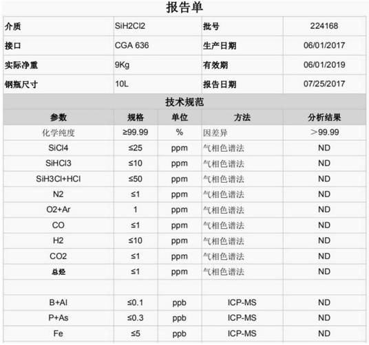
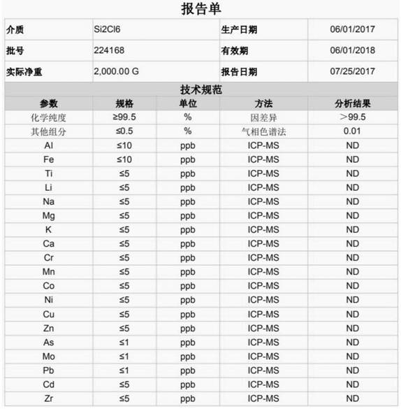
Silane, monochlorosilane, dichlorodisilane and hexachlorodisilane are prepared by the system and the method, and the prepared products are detected, and the results are shown in tables 1-4; it is found that the purity of the prepared silane is 99.9999%, the purity of monochlorosilane is as high as 97%, dichlorodisilane is 99.99% and hexachlorodisilane is 99.5%.
TABLE 1
TABLE 2
TABLE 3
TABLE 4
The embodiments in the present description are described in a progressive manner, each embodiment focuses on differences from other embodiments, and the same and similar parts among the embodiments are referred to each other. The device disclosed by the embodiment corresponds to the method disclosed by the embodiment, so that the description is simple, and the relevant points can be referred to the method part for description.
The previous description of the disclosed embodiments is provided to enable any person skilled in the art to make or use the present invention. Various modifications to these embodiments will be readily apparent to those skilled in the art, and the generic principles defined herein may be applied to other embodiments without departing from the spirit or scope of the invention. Thus, the present invention is not intended to be limited to the embodiments shown herein but is to be accorded the widest scope consistent with the principles and novel features disclosed herein.