CN112622973B - Spiral progressive cutting type impact energy dissipation method and device for vehicle - Google Patents
Spiral progressive cutting type impact energy dissipation method and device for vehicle Download PDFInfo
- Publication number
- CN112622973B CN112622973B CN202011487137.6A CN202011487137A CN112622973B CN 112622973 B CN112622973 B CN 112622973B CN 202011487137 A CN202011487137 A CN 202011487137A CN 112622973 B CN112622973 B CN 112622973B
- Authority
- CN
- China
- Prior art keywords
- cutting
- energy
- absorbing
- energy absorption
- end plate
- Prior art date
- Legal status (The legal status is an assumption and is not a legal conclusion. Google has not performed a legal analysis and makes no representation as to the accuracy of the status listed.)
- Active
Links
Images


Classifications
-
- B—PERFORMING OPERATIONS; TRANSPORTING
- B61—RAILWAYS
- B61F—RAIL VEHICLE SUSPENSIONS, e.g. UNDERFRAMES, BOGIES OR ARRANGEMENTS OF WHEEL AXLES; RAIL VEHICLES FOR USE ON TRACKS OF DIFFERENT WIDTH; PREVENTING DERAILING OF RAIL VEHICLES; WHEEL GUARDS, OBSTRUCTION REMOVERS OR THE LIKE FOR RAIL VEHICLES
- B61F19/00—Wheel guards; Bumpers; Obstruction removers or the like
- B61F19/04—Bumpers or like collision guards
Abstract
The invention discloses a spiral progressive cutting type impact energy dissipation method and device for a vehicle, wherein the energy dissipation device comprises the following components: a crushing energy-absorbing sleeve; the rear end plate is arranged at one end of the crushing type energy absorption sleeve, a through hole is formed in the rear end plate, and a cutting tool is arranged on the inner side wall of the through hole; the front end plate is arranged at one end of the crushing type energy absorption sleeve opposite to the rear end plate; cutting energy-absorbing dabber is located in the conquassation formula energy-absorbing sleeve inner chamber, and cutting energy-absorbing dabber one end is rotationally worn to establish in the through-hole, and the cutting energy-absorbing dabber other end is rotationally installed at the front end inboard, offers on the cutting energy-absorbing dabber lateral wall with cutting tool matched with spiral guiding groove. The energy dissipation device combines crushing type energy absorption and cutting type energy absorption and forms a spiral cutting mode; under the condition of the same external dimension of the energy absorption structure and the same collision translation space, the cutting stroke of the cutting tool is improved, and the energy absorption and energy absorption rate of the energy dissipation device are improved.
Description
Technical Field
The invention relates to the technical field of traffic safety protection, in particular to a spiral progressive cutting type impact energy dissipation method and device for a vehicle.
Background
For many years, rail transit becomes a widely used transportation mode by virtue of the advantages of economy, large transportation volume, quickness, environmental protection, energy conservation, little influence of climate and the like. Although rail transit has higher safety performance compared with other transportation means such as buses and cars, vehicle collision accidents happen occasionally due to the influence of various factors such as driving speed, driving density, manual operation misappropriation, equipment failure, technical loopholes and operation environment in the actual operation process. In order to ensure the safety performance of locomotive collision and reduce the damage degree to a locomotive body and passengers when the collision occurs, a locomotive safety protection device, namely an energy absorption device, is produced.
At present, an energy absorption part is installed at the end part of a vehicle, the design method is common in all countries in the world, and an energy absorption device applied to rail traffic safety is mainly a crushing piece, impact energy is quickly converted into plastic strain energy and heat energy through large plastic deformation (crushing) of thin-wall metal at the moment of collision, and the purpose of absorbing the impact energy is achieved. However, the energy absorption device of the crushing member completely depends on the shaping and large deformation of the crushing member to absorb energy, so that the crushing member has large volume and very limited energy absorption and energy absorption strokes, and brings great damage to a locomotive and passengers when the locomotive is subjected to violent impact.
Along with the improvement of the running speed of a locomotive, the traditional energy absorption mode of a crushing piece cannot meet the requirements of track traffic safety protection which is developed day by day, a novel direct cutting energy absorption device based on a metal cutting machining principle is provided, and huge collision kinetic energy is converted into cutting metal acting and heat energy to be consumed through the relative cutting motion of a cutting tool and an energy absorption element, so that the energy absorption density and the energy absorption efficiency of the energy absorption device are greatly improved, and the safety protection effect on the locomotive is realized. But is influenced by the single linear stroke path of the energy-absorbing cutting tool, the size of the energy-absorbing device in the cutting direction is larger, and the equipment volume and the energy-absorbing effect still need to be further improved.
The anti-creeper as one of the vehicle collision protection safety devices can prevent the two adjacent carriages from being folded after the vehicle collides, and can absorb partial energy to protect the safety of passengers to the maximum extent. However, due to the influence of the distance and the structure of adjacent carriages, the energy absorption efficiency and the effect of the anti-creeper adopting the thin-wall metal crushing energy absorption mode are limited, and the anti-creeper cannot further meet the development requirements of high speed and light weight in the field of rail transit.
In view of this, it is an urgent technical problem to be solved by those skilled in the art to improve and optimize the train collision energy-absorbing buffering anti-climbing device and improve the energy-absorbing rate and energy-absorbing rate of the energy-absorbing device.
Disclosure of Invention
The invention mainly aims to provide a vehicle spiral progressive cutting type impact energy dissipation method and device, and at least solves the problems that an energy absorption device in the prior art is small in energy absorption and low in energy absorption efficiency.
In order to achieve the above object, according to one aspect of the present invention, a spiral progressive cutting type impact energy dissipation method for a vehicle is provided, in which a crushing type energy absorption structure and a spiral cutting type energy absorption structure are combined to absorb collision kinetic energy by both crushing type energy absorption and spiral cutting type energy absorption.
Furthermore, the spiral cutting type energy absorption structure is sleeved inside the crushing type energy absorption structure, so that a guide support is provided for the crushing type energy absorption structure, and the overall size of the energy absorption structure is reduced.
Furthermore, a spiral guide structure is arranged on the spiral cutting type energy absorption structure, the cutting tool corresponds to the spiral guide structure in position, the spiral cutting type energy absorption structure rotates spirally while the cutting tool does not move during collision, and the cutting tool cuts the energy absorption structure spirally along the spiral guide structure.
According to another aspect of the present invention, there is provided a helical progressive cutting impact energy dissipation device for a vehicle, comprising:
a crushing energy-absorbing sleeve;
the rear end plate is arranged at one end of the crushing type energy absorption sleeve, a through hole is formed in the rear end plate, and a cutting tool is arranged on the inner side wall of the through hole;
the front end plate is arranged at one end of the crushing type energy absorption sleeve opposite to the rear end plate;
the cutting energy-absorbing mandrel is arranged in an inner cavity of the crushing energy-absorbing sleeve, one end of the cutting energy-absorbing mandrel is rotatably arranged in the through hole in a penetrating mode, the other end of the cutting energy-absorbing mandrel is rotatably arranged on the inner side of the front end plate, and a spiral guide groove matched with a cutting tool is formed in the outer side wall of the cutting energy-absorbing mandrel.
Furthermore, a plurality of cutting tools are uniformly arranged on the inner side wall of the through hole along the circumferential direction, a plurality of spiral guide grooves are formed in the outer side wall of the cutting energy-absorbing mandrel along the circumferential direction, and each cutting tool is matched with one spiral guide groove.
Further, the cutting tool comprises a cutting part, the cutting part is connected with the inner side wall of the through hole, a guide pillar is arranged on the outer side of the cutting part, the diameter of the guide pillar is smaller than the width of the cutting part, the guide pillar is contained in the spiral guide groove, and the width of the spiral guide groove is smaller than the width of the cutting part.
Further, the spiral guide groove is provided at a start portion thereof with a cutter cutting groove in which the cutting cutter is accommodated.
Further, the cutter cutting groove is a wedge-shaped groove, and the depth of the cutter cutting groove is gradually reduced from one end far away from the spiral guide groove to one end close to the spiral guide groove.
Furthermore, a plurality of layers of cutting tools are axially arranged on the inner side wall of the through hole, each layer of cutting tools comprises a plurality of cutting tools which are uniformly distributed along the circumferential direction, and the cutting tools on different layers are spirally arranged in accordance with the spiral guide groove.
Furthermore, the width of the cutting part of the first layer of cutting tool close to the front end plate is narrowest, the widths of the cutting parts of other layers are gradually increased in sequence, and the cutting depths of the multilayer cutting tools are consistent.
Further, a bearing is arranged on the inner side of the front end plate, and the cutting energy absorption core shaft is rotatably arranged on the inner side of the front end plate through the bearing.
Furthermore, an annular rib is arranged on the inner side of the rear end plate along the circumferential direction of the through hole, the annular rib extends towards the front end plate along the axial direction of the cutting energy-absorbing mandrel, and the cutting energy-absorbing mandrel is rotatably arranged in the annular rib in a penetrating mode.
Furthermore, a honeycomb energy absorption structure is filled between the crushing type energy absorption sleeve and the cutting energy absorption mandrel, and the honeycomb energy absorption structure is a periodic cell structure.
Furthermore, the outer side of the front end plate is provided with an anti-climbing tooth.
By applying the technical scheme of the invention, the crushing type energy absorption sleeve is arranged, the cutting energy absorption mandrel is arranged in the crushing type energy absorption sleeve, one end of the cutting energy absorption mandrel is rotatably arranged in the through hole in a penetrating way, the other end of the cutting energy absorption mandrel is rotatably arranged at the inner side of the front end plate, the cutting tool is arranged on the inner side wall of the through hole, and the spiral guide groove matched with the cutting tool is arranged on the outer side wall of the cutting energy absorption mandrel; when a vehicle has a collision accident, the front end plate is compressed backwards by the impact force, and the crushing type energy absorption sleeve is crushed; meanwhile, the fixed cutting tool carries out spiral cutting on the cutting energy-absorbing core shaft along the spiral guide groove, so that the cutting energy-absorbing core shaft carries out axial movement and spiral movement of circumferential rotation. The vehicle spiral progressive cutting type impact energy dissipation device combines crushing type energy absorption and cutting type energy absorption, converts single axial translation of a traditional cutting energy absorption device into axial and circumferential spiral combined motion, improves the cutting stroke of a cutting tool under the same energy absorption structure outline dimension and the same collision translation space, and accordingly improves the energy absorption rate and the energy absorption rate of the energy dissipation device. Meanwhile, the cutting energy-absorbing core shaft can provide a guiding effect for the crushing type energy-absorbing sleeve, and the energy-absorbing stability of the structure is improved.
In addition to the objects, features and advantages described above, other objects, features and advantages of the present invention are also provided. The present invention will be described in further detail below with reference to the accompanying drawings.
Drawings
The accompanying drawings, which are incorporated in and constitute a part of this application, illustrate embodiments of the invention and, together with the description, serve to explain the invention and not to limit the invention. In the drawings:
fig. 1 is a cross-sectional view of an energy dissipation device of embodiment 2 of the present invention.
Fig. 2 is a partially enlarged view of a portion B in fig. 1.
Fig. 3 is a partially enlarged view of C in fig. 1.
Fig. 4 is an isometric view of an energy dissipation device of example 2 of the invention.
Fig. 5 is a sectional view taken along the plane a-a in fig. 4.
Fig. 6 is an isometric view of another orientation of the energy dissipation device of example 2 of the present invention.
Fig. 7 is a partial enlarged view of fig. 6 at D.
Fig. 8 is a structural view of a rear end plate in the energy dissipating device of embodiment 2 of the present invention.
Fig. 9 is a partial enlarged view at E in fig. 8.
FIG. 10 is a structural view of the energy absorbing core cut in the energy dissipating device of example 2 of the present invention as it is squared.
Fig. 11 is a partial enlarged view of fig. 10 at F.
Fig. 12 is a structural view of the energy dissipation device according to example 2 of the present invention when the cutting energy absorbing core is erected.
Fig. 13 is an assembly structural view of a cutting energy absorbing mandrel and a rear end plate in the energy dissipation device of example 2 of the present invention.
Fig. 14 is an assembly structure view of the energy dissipation device of example 2 of the present invention in another direction of the cutting energy absorption mandrel and the rear end plate.
Fig. 15 is a structural view of a front end plate and a climbing prevention tooth in the energy dissipation device of embodiment 2 of the present invention.
Fig. 16 is a structural view of the front end plate and the anticreeper teeth in the energy consuming device of embodiment 2 of the present invention in another direction.
Fig. 17 is an assembly structural view of a cutting energy-absorbing mandrel, a front end plate and a climbing prevention tooth in the energy dissipation device of example 2 of the present invention.
Fig. 18 is a structural view of a crushable energy absorber sleeve in an energy dissipating device of example 2 of this invention.
Fig. 19 is a schematic structural view of a cutting tool on a rear end plate in the energy dissipating device according to embodiment 3 of the present invention in a multi-layer state.
Fig. 20 is a partial enlarged view at G in fig. 19.
Fig. 21 is a cross-sectional view of an energy dissipation device of embodiment 4 of the present invention.
Fig. 22 is a schematic cross-sectional view of an energy dissipation device of embodiment 4 of the present invention.
Wherein the figures include the following reference numerals:
1. a crushing energy-absorbing sleeve; 2. a rear end plate; 3. a front end plate; 4. cutting the energy absorption mandrel; 5. anti-climbing teeth; 6. a honeycomb energy-absorbing structure; 21. a through hole; 22. a cutting tool; 23. an annular flange; 31. a bearing; 41. a spiral guide groove; 221. a cutting portion; 222. a guide post; 411. the cutter cuts the groove.
Detailed Description
In order to facilitate an understanding of the invention, the invention will be described more fully and in detail below with reference to the accompanying drawings and preferred embodiments, but the scope of the invention is not limited to the specific embodiments below. It should be noted that the embodiments and features of the embodiments may be combined with each other without conflict.
Unless otherwise defined, all terms of art used hereinafter have the same meaning as commonly understood by one of ordinary skill in the art. The use of the words "a" or "an" and the like in the description and claims of the present patent application do not denote a limitation of quantity, but rather denote the presence of at least one. The terms "connected" and "coupled" and the like are not restricted to direct connections, but may be indirectly connected through other intermediate connections. "upper", "lower", "left", "right", and the like are used merely to indicate relative positional relationships, and when the absolute position of the object being described is changed, the relative positional relationships are changed accordingly.
Example 1:
according to the vehicle spiral progressive cutting type impact energy dissipation method, a crushing type energy absorption structure and a spiral cutting type energy absorption structure are combined, and collision kinetic energy is absorbed together through two modes of crushing type energy absorption and spiral cutting type energy absorption. The design method combines a crushing type energy absorption mode and a spiral cutting type energy absorption mode, converts single axial translation of the traditional cutting energy absorption device into axial and circumferential spiral combined motion, and improves the energy absorption rate and the energy absorption rate of the device.
Furthermore, the spiral cutting type energy absorption structure is sleeved inside the crushing type energy absorption structure, so that a guide support is provided for the crushing type energy absorption structure, and the overall size of the energy absorption structure is reduced. By the arrangement, under the condition of the same overall dimension of the energy absorption structure and the same collision translation space, the energy absorption and energy absorption rate of the energy dissipation device are further improved.
Specifically, a spiral guide structure is arranged on the spiral cutting type energy absorption structure, the cutting tool corresponds to the spiral guide structure in position, the spiral cutting type energy absorption structure rotates while the cutting tool does not move during collision, and the cutting tool spirally cuts the energy absorption structure along the spiral guide structure.
Example 2:
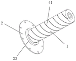
referring to fig. 1 to 18, a vehicle spiral progressive cutting impact energy dissipation device according to an embodiment of the present invention mainly includes a crushing energy absorption sleeve 1, a rear end plate 2, a front end plate 3, and a cutting energy absorption mandrel 4. The rear end plate 2 is arranged at one end of the crushing type energy-absorbing sleeve 1, and the front end plate 3 is arranged at one end of the crushing type energy-absorbing sleeve 1 opposite to the rear end plate 2; a through hole 21 is formed in the rear end plate 2, and a cutting tool 22 is mounted on the inner side wall of the through hole 21; the cutting energy-absorbing mandrel 4 is arranged in the inner cavity of the crushing energy-absorbing sleeve 1, one end of the cutting energy-absorbing mandrel 4 is rotatably arranged in the through hole 21 in a penetrating way, the other end of the cutting energy-absorbing mandrel 4 is rotatably arranged on the inner side of the front end plate 3, and the outer side wall of the cutting energy-absorbing mandrel 4 is provided with a spiral guide groove 41 matched with the cutting tool 22.
The spiral progressive cutting type impact energy dissipation device for the vehicle is characterized in that a crushing type energy absorption sleeve 1 is arranged, a cutting energy absorption mandrel 4 is arranged in the crushing type energy absorption sleeve 1, one end of the cutting energy absorption mandrel 4 is rotatably arranged in a through hole 21 in a penetrating mode, the other end of the cutting energy absorption mandrel 4 is rotatably arranged on the inner side of a front end plate 3, a cutting tool 22 is arranged on the inner side wall of the through hole 21, and a spiral guide groove 41 matched with the cutting tool 22 is formed in the outer side wall of the cutting energy absorption mandrel 4; the energy dissipation device is arranged on the body of the rail vehicle through the rear end plate 2, and when the vehicle has a collision accident, the front end plate 3 is compressed backwards under the impact force to crush the crushing type energy absorption sleeve 1; at the same time, the fixed cutting tool 22 spirally cuts the cutting power core 4 along the spiral guide groove 41, so that the cutting power core 4 makes a spiral combined motion of axial movement and circumferential rotation, and the cut cutting power core 4 protrudes from the through hole 21. The energy dissipation device combines crushing type energy absorption and cutting energy absorption, converts single axial translation of the traditional cutting energy absorption device into axial and circumferential spiral combined motion, and improves the cutting stroke of the cutting tool 22 under the same energy absorption structure outline dimension and the same collision translation space, thereby improving the energy absorption and energy absorption rate of the energy dissipation device. In addition, the cutting energy-absorbing mandrel 4 in the energy dissipation device is also a guide part of the crushing energy-absorbing sleeve 1, so that the centering crushing precision of the crushing energy-absorbing sleeve 1 is greatly improved, the generation of unfavorable structural crushing phenomena such as unbalance loading and the like is reduced, and the energy-absorbing efficiency of the crushing energy-absorbing sleeve 1 is improved. The energy dissipation device has large integral compression energy absorption stroke and high axial space utilization rate.
Specifically, referring to fig. 1, 2, 6 and 7, in the present embodiment, a plurality of cutting tools 22 are uniformly installed on the inner side wall of the through hole 21 along the circumferential direction thereof, a plurality of spiral guide grooves 41 are opened on the outer side wall of the cutting energy absorbing core 4 along the circumferential direction thereof, and each cutting tool 22 is matched with one spiral guide groove 41. Further, the number of the cutting inserts 22 is at least 3, and the number of the spiral guide grooves 41 corresponds to the number of the cutting inserts 22. The size of the cutting tool 22 can be designed and installed according to the cutting energy absorption required by the device.
Further, referring to fig. 7 and 9, in the present embodiment, the cutting tool 22 includes a cutting part 221, the cutting part 221 is connected with an inner sidewall of the through-hole 21, a guide post 222 is provided outside the cutting part 221, a diameter of the guide post 222 is smaller than a width of the cutting part 221, the guide post 222 is received in the spiral guide groove 41, and the width of the spiral guide groove 41 is smaller than the width of the cutting part 221. By providing a guide post 222 at the front end of the cutting tool 22, the guide post 222 is engaged with the spiral guide groove 41; meanwhile, the side edge of the cutting tool 22 is a cutting part 221, and the absorption of the main external energy of the energy dissipation device is completed through the combination of the cutting action of the cutting energy absorption mandrel 4 and the crushing action of the crushing energy absorption sleeve 1 through the cutting part 221. The opening depth and width of the spiral guide groove 41 are determined by the guide post 222.
The pitch of the spiral guide groove 41 is determined by the critical condition that the cutting energy absorbing core 4 can be changed into the spiral motion when the cutting tool 22 moves axially relative to the cutting energy absorbing core 4, and the pitch is measured by analyzing the stress relation of the cutting tool 22The helix angle θ is calculated and the pitch is then determined based on the distance of the cutting insert 22 from the center point of rotation. Helix angle θ, cutting force FCutting forceWith impact thrust FImpact forceThe following relationship should be satisfied theoretically:
Fcutting force≤FImpact force(sinθ-μcosθ)
The specific value of the pitch L is nd · tan θ (d is the diameter of the spiral line), and the specific value of the pitch of the spiral guide groove 41 can be set and adjusted according to the practical application of the energy dissipation device, so as to ensure that the cutting energy absorbing core 4 can rotate in the circumferential direction when a collision occurs.
Referring to fig. 11 and 12, in the present embodiment, the start of the spiral guide groove 41 is provided with a cutter cutting groove 411, and the cutting tool 22 is received in the cutter cutting groove 411. Further, the tool cutting flutes 411 are wedge flutes; the depth of the cutter cutting groove 411 gradually decreases from an end distant from the spiral guide groove 41 to an end close to the spiral guide groove 41. So configured, before the cutting insert 22 begins cutting, it is located within the insert cutting pocket 411; because the cutter cutting groove 411 is a wedge-shaped groove, the cutting thickness is gradually increased in sequence when the cutting cutter 22 starts to cut under the action of thrust, so that the cutting stability is ensured, and the occurrence of edge breakage or breakage accidents caused by the fact that the cutting cutter 22 bears large impact load is avoided.
Specifically, referring to fig. 1, 3 and 5, in the present embodiment, a bearing 31 is installed inside the front end plate 3, and the cutting energy absorbing core 4 is rotatably installed inside the front end plate 3 through the bearing 31. With this arrangement, when a collision occurs, the cutting energy-absorbing mandrel 4 circumferentially rotates under the spiral cutting action force of the cutting tool 22, and the upper end of the cutting energy-absorbing mandrel 4 rotates relative to the front end plate 3 under the action of the bearing 31, so that the cutting energy-absorbing mandrel 4 can perform spiral motion smoothly as a whole, and spiral cutting of the cutting energy-absorbing mandrel 4 is realized.
Referring to fig. 1, 2, 5 and 8, in the present embodiment, an annular rib 23 is further provided on the inner side of the rear end plate 2 along the circumferential direction of the through hole 21, the annular rib 23 extends toward the front end plate 3 along the axial direction of the cutting energy-absorbing core 4, and the cutting energy-absorbing core 4 is rotatably inserted into the annular rib 23. The arrangement of the annular rib 23 can stabilize the cutting energy absorption mandrel 4 and the rear end plate 2.
Referring to fig. 1, 3 to 5, in the present embodiment, a climbing prevention tooth 5 is further provided on the outer side of the front end plate 3, and the climbing prevention tooth 5 is integrally formed with the front end plate 3. Two energy dissipation devices of the invention are oppositely arranged on two adjacent carriages of the vehicle, and the anti-climbing teeth 5 in the two energy dissipation devices are oppositely arranged. When collision occurs, the anti-climbing teeth 5 in the two energy dissipation devices are meshed to play a role of preventing the climbing vehicle.
The working principle of the energy dissipation device is as follows: when collision occurs, the front end plate 3 is compressed backwards under the impact force, and the crushing type energy absorption sleeve 1 is crushed; meanwhile, the fixed cutting tool 22 performs spiral cutting on the cutting energy-absorbing mandrel 4 along the spiral guide groove 41, so that the cutting energy-absorbing mandrel 4 performs spiral combined motion of axial motion and circumferential rotation, the cutting energy-absorbing mandrel 4 performs spiral motion along the axis of the cutting energy-absorbing mandrel 4, the cut cutting energy-absorbing mandrel 4 extends out of the through hole 21, and the anti-climbing teeth 5 at the front end of the device play a role in preventing climbing.
Generally speaking, the energy dissipation device integrates crushing type energy absorption and cutting type energy absorption, and greatly improves the energy absorption and energy absorption rate of the energy dissipation device in a limited space.
The single axial translation of the traditional cutting energy absorption device is converted into the axial and circumferential spiral combined motion, and the cutting stroke of the cutting tool 22 is improved under the same external dimension of the energy absorption structure and the same collision translation space, so that the energy absorption and energy absorption rate of the energy dissipation device are improved.
The cutting energy-absorbing mandrel 4 in the energy dissipation device is also a guide part of the crushing type energy-absorbing sleeve 1, so that the centering crushing precision of the crushing type energy-absorbing sleeve 1 is greatly improved, the generation of the phenomenon that unbalance loading and the like are not beneficial to structural crushing is reduced, and the energy-absorbing efficiency of the crushing type energy-absorbing sleeve 1 is improved.
Through setting up multilayer cutting tool 22, multilayer cutting tool 22 in same spiral guiding groove 41 carries out progressive cutting to spiral guiding groove 41 in proper order, and cutting force progressively improves, has improved the cutting area utilization ratio of cutting energy-absorbing dabber 4, when guaranteeing device cutting stability, has further promoted energy absorption and the energy-absorbing rate of energy dissipation device.
The energy dissipation device utilizes the space at the bottom of the vehicle body to absorb the cutting stroke in time, the utilization rate in the axial space is greatly increased, the compression stroke can far exceed the limit cutting stroke of a conventional cutting energy absorption device according to the design requirement, and the equipment applicability and the appearance aesthetics of the vehicle of the energy dissipation device are improved.
Example 3:
referring to fig. 19 to 20, the main structure of a spiral progressive cutting type impact energy dissipation device for a vehicle according to another embodiment of the present invention is the same as that of embodiment 2, and will not be described again. Compared with embodiment 2, the energy dissipation device of the present embodiment is mainly different in that a plurality of layers of cutting tools 22 are axially disposed on the inner side wall of the through hole 21 and the inner side wall of the annular rib 23, each layer includes a plurality of cutting tools 22 uniformly disposed along the circumferential direction, and the cutting tools 22 of different layers are spirally disposed in correspondence with the spiral guide groove 41 (as shown in fig. 20, the same broken line indicates the cutting tools 22 of the same layer). One cutting tool 22 in each layer is accommodated in the same spiral guide groove 41; the width of the cutting portion 221 of the first layer cutting tool 22 on the side closer to the front end plate 3 is the narrowest, and the widths of the cutting portions 221 of the cutting tools 22 of the other layers are sequentially increased in steps, but the cutting depth is kept constant (as shown in fig. 20, the right broken line indicates the first layer cutting tool 22 on the side closer to the front end plate 3).
With this arrangement, the multiple layers of cutting tools 22 in the same spiral guide groove 41 progressively cut the spiral guide groove 41 in sequence, and the cutting force is gradually increased (because the width of the cutting portion 221 is gradually increased in sequence); compared with the energy dissipation device in the embodiment 1, the energy dissipation device in the embodiment further improves the utilization rate of the cutting area of the cutting energy-absorbing mandrel 4, and can further improve the energy absorption rate and the energy absorption rate of the energy dissipation device while ensuring the cutting stability of the device.
Example 4:
referring to fig. 21 and 22, a spiral progressive cutting type impact energy dissipation device for a vehicle according to another embodiment of the present invention has the same main structure as that of embodiment 3, and will not be described herein again. Compared with the embodiment 3, the energy dissipation device of the embodiment is mainly characterized in that a honeycomb energy absorption structure 6 is further filled between the crushing type energy absorption sleeve 1 and the cutting energy absorption mandrel 4, the honeycomb energy absorption structure 6 is a periodic cell structure with adjustable wall thickness gradient, the wall thickness of the honeycomb energy absorption structure is between 0.06mm and 0.5mm, and the honeycomb energy absorption structure is in continuous gradient or discrete gradient. The honeycomb energy absorption structure 6 is filled between the crushing type energy absorption sleeve 1 and the cutting energy absorption mandrel 4, so that the cutting stability of the cutter in the cutting stroke of the energy dissipation device can be further improved, and the energy absorption rate of the energy dissipation device in unit volume is improved.
The above description is only a preferred embodiment of the present invention and is not intended to limit the present invention, and various modifications and changes may be made by those skilled in the art. Any modification, equivalent replacement, or improvement made within the spirit and principle of the present invention should be included in the protection scope of the present invention.
Claims (5)
1. A vehicular spiral progressive cutting impact energy dissipation device, comprising:
a crushing energy-absorbing sleeve (1);
the rear end plate (2) is mounted at one end of the crushing type energy absorption sleeve (1), a through hole (21) is formed in the rear end plate (2), and a cutting tool (22) is mounted on the inner side wall of the through hole (21);
the front end plate (3) is arranged at one end of the crushing type energy absorption sleeve (1) opposite to the rear end plate (2);
the cutting energy-absorbing mandrel (4) is arranged in the inner cavity of the crushing energy-absorbing sleeve (1), one end of the cutting energy-absorbing mandrel (4) is rotatably arranged in the through hole (21) in a penetrating mode, the other end of the cutting energy-absorbing mandrel (4) is rotatably arranged on the inner side of the front end plate (3), and a spiral guide groove (41) matched with the cutting tool (22) is formed in the outer side wall of the cutting energy-absorbing mandrel (4);
a plurality of cutting tools (22) are uniformly arranged on the inner side wall of the through hole (21) along the circumferential direction, a plurality of spiral guide grooves (41) are formed on the outer side wall of the cutting energy-absorbing core shaft (4) along the circumferential direction, and each cutting tool (22) is matched with one spiral guide groove (41);
the cutting tool (22) comprises a cutting part (221), the cutting part (221) is connected with the inner side wall of the through hole (21), a guide post (222) is arranged on the outer side of the cutting part (221), the diameter of the guide post (222) is smaller than the width of the cutting part (221), the guide post (222) is accommodated in the spiral guide groove (41), and the width of the spiral guide groove (41) is smaller than the width of the cutting part (221); the starting part of the spiral guide groove (41) is provided with a cutter cutting groove (411), and the cutting cutter (22) is accommodated in the cutter cutting groove (411).
2. The vehicular spiral progressive cutting impact energy dissipation device according to claim 1, wherein the cutter cutting flutes (411) are wedge-shaped flutes, and the depth of the cutter cutting flutes (411) gradually decreases from an end away from the spiral guide groove (41) to an end close to the spiral guide groove (41).
3. The vehicle spiral progressive impact energy dissipation device according to claim 1, wherein a plurality of layers of the cutting tools (22) are axially disposed on the inner side wall of the through hole (21), each layer includes a plurality of the cutting tools (22) uniformly disposed along the circumferential direction, and the cutting tools (22) of different layers are spirally disposed in accordance with the spiral guide groove (41).
4. The spiral progressive impact energy dissipation device for vehicle according to claim 1, wherein the width of the cutting portion (221) of the first layer of the cutting tool (22) near the front end plate (3) is narrowest, the width of the cutting portion (221) of the other layers is gradually increased in sequence, and the cutting depth of the plurality of layers of the cutting tool (22) is uniform.
5. The vehicle spiral progressive cutting type impact energy dissipation device according to any one of claims 1 to 4, wherein a bearing (31) is mounted on the inner side of the front end plate (3), and the cutting energy absorption core shaft (4) is rotatably mounted on the inner side of the front end plate (3) through the bearing (31); an annular rib (23) is arranged on the inner side of the rear end plate (2) along the circumferential direction of the through hole (21), the annular rib (23) extends towards the front end plate (3) along the axial direction of the cutting energy-absorbing mandrel (4), and the cutting energy-absorbing mandrel (4) is rotatably arranged in the annular rib (23) in a penetrating manner; a honeycomb energy absorption structure (6) with adjustable wall thickness gradient is filled between the crushing type energy absorption sleeve (1) and the cutting energy absorption mandrel (4); the outer side of the front end plate (3) is provided with an anti-climbing tooth (5).
Priority Applications (1)
| Application Number | Priority Date | Filing Date | Title |
|---|---|---|---|
| CN202011487137.6A CN112622973B (en) | 2020-12-16 | 2020-12-16 | Spiral progressive cutting type impact energy dissipation method and device for vehicle |
Applications Claiming Priority (1)
| Application Number | Priority Date | Filing Date | Title |
|---|---|---|---|
| CN202011487137.6A CN112622973B (en) | 2020-12-16 | 2020-12-16 | Spiral progressive cutting type impact energy dissipation method and device for vehicle |
Publications (2)
| Publication Number | Publication Date |
|---|---|
| CN112622973A CN112622973A (en) | 2021-04-09 |
| CN112622973B true CN112622973B (en) | 2022-03-25 |
Family
ID=75313939
Family Applications (1)
| Application Number | Title | Priority Date | Filing Date |
|---|---|---|---|
| CN202011487137.6A Active CN112622973B (en) | 2020-12-16 | 2020-12-16 | Spiral progressive cutting type impact energy dissipation method and device for vehicle |
Country Status (1)
| Country | Link |
|---|---|
| CN (1) | CN112622973B (en) |
Families Citing this family (2)
| Publication number | Priority date | Publication date | Assignee | Title |
|---|---|---|---|---|
| CN113830129B (en) * | 2021-11-10 | 2024-04-26 | 中车南京浦镇车辆有限公司 | Planing type anti-creeper for railway vehicle |
| CN115158388B (en) * | 2022-08-04 | 2023-12-05 | 中南大学 | Shrinkage type deflection-preventing energy-absorbing anti-climbing device |
Citations (6)
| Publication number | Priority date | Publication date | Assignee | Title |
|---|---|---|---|---|
| FR2528928A1 (en) * | 1982-06-21 | 1983-12-23 | Picand Roland | Collapsible shock absorber for continuous tube cutter - has continuous cutting action and deflector to divert separated tube end |
| CN102107664A (en) * | 2011-01-21 | 2011-06-29 | 中南大学 | Vehicle cutting energy absorption device for rail locomotive |
| CN103818402A (en) * | 2014-03-13 | 2014-05-28 | 西南交通大学 | Energy absorbing anti-creep device for track traffic vehicles |
| CN206871011U (en) * | 2017-05-12 | 2018-01-12 | 长安大学 | Car crass multi-buffer energy absorption device |
| CN207060058U (en) * | 2017-07-11 | 2018-03-02 | 深圳市乾行达科技有限公司 | Anticreeper |
| CN211107436U (en) * | 2019-10-15 | 2020-07-28 | 武汉中车长客轨道车辆有限公司 | Planing type anti-creep device |
-
2020
- 2020-12-16 CN CN202011487137.6A patent/CN112622973B/en active Active
Patent Citations (6)
| Publication number | Priority date | Publication date | Assignee | Title |
|---|---|---|---|---|
| FR2528928A1 (en) * | 1982-06-21 | 1983-12-23 | Picand Roland | Collapsible shock absorber for continuous tube cutter - has continuous cutting action and deflector to divert separated tube end |
| CN102107664A (en) * | 2011-01-21 | 2011-06-29 | 中南大学 | Vehicle cutting energy absorption device for rail locomotive |
| CN103818402A (en) * | 2014-03-13 | 2014-05-28 | 西南交通大学 | Energy absorbing anti-creep device for track traffic vehicles |
| CN206871011U (en) * | 2017-05-12 | 2018-01-12 | 长安大学 | Car crass multi-buffer energy absorption device |
| CN207060058U (en) * | 2017-07-11 | 2018-03-02 | 深圳市乾行达科技有限公司 | Anticreeper |
| CN211107436U (en) * | 2019-10-15 | 2020-07-28 | 武汉中车长客轨道车辆有限公司 | Planing type anti-creep device |
Also Published As
| Publication number | Publication date |
|---|---|
| CN112622973A (en) | 2021-04-09 |
Similar Documents
| Publication | Publication Date | Title |
|---|---|---|
| CN112706794B (en) | Multi-stage spiral cutting type structure design method for coupled crushing and energy-absorbing anti-climbing device | |
| CN112622973B (en) | Spiral progressive cutting type impact energy dissipation method and device for vehicle | |
| WO2017063600A1 (en) | Telescopic energy-absorbing device for rail vehicle collisions | |
| EP3424794B1 (en) | Collision energy absorption apparatus for rail vehicles | |
| EP3611071B1 (en) | Energy-absorbing anti-creeper and train vehicle with energy-absorbing anti-creeper | |
| CN202783043U (en) | Automobile energy adsorption box | |
| CN103818402A (en) | Energy absorbing anti-creep device for track traffic vehicles | |
| CN106672010A (en) | Motor train unit head train passive safety protection device | |
| CN113830128B (en) | Metal energy absorption device | |
| CN104590178A (en) | Automobile energy absorption box | |
| CN106428090A (en) | Cutting extrusion type anti-creeping energy absorbing device | |
| CN205292666U (en) | Rail vehicle anticreeper | |
| CN206288027U (en) | A kind of EMUs head car passive security protector | |
| CN109367561B (en) | Cutting type energy-absorbing anti-creeper for railway vehicle | |
| CN206552049U (en) | A kind of anti-climbing energy-absorbing device for the vehicles | |
| EP3357785B1 (en) | Energy absorption device and rail vehicle having same | |
| CN210971086U (en) | Energy-absorbing anti-climbing device for railway vehicle | |
| CN113830129B (en) | Planing type anti-creeper for railway vehicle | |
| CN114604285A (en) | Anti-climbing energy-absorbing device | |
| CN110816579A (en) | Energy-absorbing anti-climbing device for railway vehicle | |
| CN203766810U (en) | Energy absorbing anti-climbing device for rail transit vehicle | |
| CN209176699U (en) | A kind of cutting type rail vehicle energy-absorbing anti-creeper | |
| CN105034998B (en) | Bump energy-absorbing device and automobile with same | |
| CN212709293U (en) | Lightweight car bumper crossbeam | |
| CN115214739B (en) | Energy-absorbing structure and energy-absorbing anti-creep device |
Legal Events
| Date | Code | Title | Description |
|---|---|---|---|
| PB01 | Publication | ||
| PB01 | Publication | ||
| SE01 | Entry into force of request for substantive examination | ||
| SE01 | Entry into force of request for substantive examination | ||
| GR01 | Patent grant | ||
| GR01 | Patent grant |