CN112601577A - Adaptive VFA cardiac therapy - Google Patents
Adaptive VFA cardiac therapy Download PDFInfo
- Publication number
- CN112601577A CN112601577A CN201980056140.1A CN201980056140A CN112601577A CN 112601577 A CN112601577 A CN 112601577A CN 201980056140 A CN201980056140 A CN 201980056140A CN 112601577 A CN112601577 A CN 112601577A
- Authority
- CN
- China
- Prior art keywords
- pacing
- heart
- electrode
- patient
- therapy
- Prior art date
- Legal status (The legal status is an assumption and is not a legal conclusion. Google has not performed a legal analysis and makes no representation as to the accuracy of the status listed.)
- Pending
Links
- 229940030602 cardiac therapy drug Drugs 0.000 title claims abstract description 62
- 230000003044 adaptive effect Effects 0.000 title abstract description 8
- 210000002216 heart Anatomy 0.000 claims abstract description 294
- 238000002560 therapeutic procedure Methods 0.000 claims abstract description 169
- 230000001746 atrial effect Effects 0.000 claims abstract description 157
- 230000002861 ventricular Effects 0.000 claims abstract description 122
- 230000000747 cardiac effect Effects 0.000 claims abstract description 88
- 210000005245 right atrium Anatomy 0.000 claims abstract description 62
- 230000006461 physiological response Effects 0.000 claims abstract description 47
- 210000003205 muscle Anatomy 0.000 claims abstract description 39
- 210000001174 endocardium Anatomy 0.000 claims abstract description 27
- 230000004044 response Effects 0.000 claims abstract description 18
- 238000000034 method Methods 0.000 claims description 113
- 230000000694 effects Effects 0.000 claims description 95
- 210000005240 left ventricle Anatomy 0.000 claims description 75
- 230000004913 activation Effects 0.000 claims description 46
- 210000001519 tissue Anatomy 0.000 claims description 42
- 230000004048 modification Effects 0.000 claims description 31
- 238000012986 modification Methods 0.000 claims description 31
- 210000005241 right ventricle Anatomy 0.000 claims description 29
- 230000001934 delay Effects 0.000 claims description 24
- 238000012545 processing Methods 0.000 claims description 24
- 125000006850 spacer group Chemical group 0.000 claims description 23
- 230000004217 heart function Effects 0.000 claims description 22
- 210000002186 septum of brain Anatomy 0.000 claims description 19
- 238000003384 imaging method Methods 0.000 claims description 17
- 230000033764 rhythmic process Effects 0.000 claims description 14
- 238000012544 monitoring process Methods 0.000 claims description 13
- 230000028161 membrane depolarization Effects 0.000 claims description 12
- 230000006870 function Effects 0.000 abstract description 19
- 239000013598 vector Substances 0.000 description 35
- 238000005259 measurement Methods 0.000 description 25
- 230000008602 contraction Effects 0.000 description 19
- 238000010586 diagram Methods 0.000 description 19
- 238000001514 detection method Methods 0.000 description 18
- 230000009977 dual effect Effects 0.000 description 18
- 208000001871 Tachycardia Diseases 0.000 description 16
- 239000007943 implant Substances 0.000 description 15
- 238000005457 optimization Methods 0.000 description 13
- 230000006794 tachycardia Effects 0.000 description 13
- 230000000875 corresponding effect Effects 0.000 description 12
- 230000008569 process Effects 0.000 description 12
- 238000012360 testing method Methods 0.000 description 12
- 238000009125 cardiac resynchronization therapy Methods 0.000 description 11
- 238000004891 communication Methods 0.000 description 11
- 230000003205 diastolic effect Effects 0.000 description 10
- 230000000638 stimulation Effects 0.000 description 10
- 238000002633 shock therapy Methods 0.000 description 9
- 230000002123 temporal effect Effects 0.000 description 9
- 239000011248 coating agent Substances 0.000 description 8
- 238000000576 coating method Methods 0.000 description 8
- 238000002591 computed tomography Methods 0.000 description 8
- 210000002837 heart atrium Anatomy 0.000 description 8
- 230000001360 synchronised effect Effects 0.000 description 8
- 206010006580 Bundle branch block left Diseases 0.000 description 7
- 206010006578 Bundle-Branch Block Diseases 0.000 description 7
- 230000009286 beneficial effect Effects 0.000 description 7
- 239000004020 conductor Substances 0.000 description 7
- 210000005003 heart tissue Anatomy 0.000 description 7
- 238000002513 implantation Methods 0.000 description 7
- 201000001715 left bundle branch hemiblock Diseases 0.000 description 7
- 210000001992 atrioventricular node Anatomy 0.000 description 6
- 230000008901 benefit Effects 0.000 description 6
- 239000003990 capacitor Substances 0.000 description 6
- 230000001276 controlling effect Effects 0.000 description 6
- 238000001914 filtration Methods 0.000 description 6
- BASFCYQUMIYNBI-UHFFFAOYSA-N platinum Chemical compound [Pt] BASFCYQUMIYNBI-UHFFFAOYSA-N 0.000 description 6
- 230000035939 shock Effects 0.000 description 6
- 230000001960 triggered effect Effects 0.000 description 6
- 238000004458 analytical method Methods 0.000 description 5
- 210000003484 anatomy Anatomy 0.000 description 5
- 239000013078 crystal Substances 0.000 description 5
- 230000000149 penetrating effect Effects 0.000 description 5
- 238000007920 subcutaneous administration Methods 0.000 description 5
- 230000001225 therapeutic effect Effects 0.000 description 5
- 238000011282 treatment Methods 0.000 description 5
- 210000000591 tricuspid valve Anatomy 0.000 description 5
- 238000002604 ultrasonography Methods 0.000 description 5
- 210000000596 ventricular septum Anatomy 0.000 description 5
- 206010047302 ventricular tachycardia Diseases 0.000 description 5
- 239000004593 Epoxy Substances 0.000 description 4
- RTAQQCXQSZGOHL-UHFFFAOYSA-N Titanium Chemical compound [Ti] RTAQQCXQSZGOHL-UHFFFAOYSA-N 0.000 description 4
- 206010003119 arrhythmia Diseases 0.000 description 4
- 230000006793 arrhythmia Effects 0.000 description 4
- 210000004375 bundle of his Anatomy 0.000 description 4
- 210000005242 cardiac chamber Anatomy 0.000 description 4
- 230000008878 coupling Effects 0.000 description 4
- 238000010168 coupling process Methods 0.000 description 4
- 238000005859 coupling reaction Methods 0.000 description 4
- 238000002595 magnetic resonance imaging Methods 0.000 description 4
- 210000004115 mitral valve Anatomy 0.000 description 4
- 239000012811 non-conductive material Substances 0.000 description 4
- 229920000052 poly(p-xylylene) Polymers 0.000 description 4
- 229920001296 polysiloxane Polymers 0.000 description 4
- 229920002635 polyurethane Polymers 0.000 description 4
- 239000004814 polyurethane Substances 0.000 description 4
- 239000000758 substrate Substances 0.000 description 4
- 239000010936 titanium Substances 0.000 description 4
- 229910052719 titanium Inorganic materials 0.000 description 4
- 206010019280 Heart failures Diseases 0.000 description 3
- 206010071186 Ventricular dyssynchrony Diseases 0.000 description 3
- 229910045601 alloy Inorganic materials 0.000 description 3
- 239000000956 alloy Substances 0.000 description 3
- 210000001765 aortic valve Anatomy 0.000 description 3
- 238000013459 approach Methods 0.000 description 3
- 230000000712 assembly Effects 0.000 description 3
- 238000000429 assembly Methods 0.000 description 3
- 206010003668 atrial tachycardia Diseases 0.000 description 3
- 238000005452 bending Methods 0.000 description 3
- 230000008859 change Effects 0.000 description 3
- 238000012937 correction Methods 0.000 description 3
- 238000013500 data storage Methods 0.000 description 3
- 239000006185 dispersion Substances 0.000 description 3
- 238000005516 engineering process Methods 0.000 description 3
- 238000011156 evaluation Methods 0.000 description 3
- 239000004744 fabric Substances 0.000 description 3
- 230000000004 hemodynamic effect Effects 0.000 description 3
- 208000037909 invasive meningococcal disease Diseases 0.000 description 3
- 230000007246 mechanism Effects 0.000 description 3
- 210000004165 myocardium Anatomy 0.000 description 3
- 229910052697 platinum Inorganic materials 0.000 description 3
- 210000001147 pulmonary artery Anatomy 0.000 description 3
- 210000003102 pulmonary valve Anatomy 0.000 description 3
- 238000000718 qrs complex Methods 0.000 description 3
- 230000002829 reductive effect Effects 0.000 description 3
- 230000011664 signaling Effects 0.000 description 3
- 206010003130 Arrhythmia supraventricular Diseases 0.000 description 2
- 206010003658 Atrial Fibrillation Diseases 0.000 description 2
- 208000014526 Conduction disease Diseases 0.000 description 2
- 208000033988 Device pacing issue Diseases 0.000 description 2
- 239000004696 Poly ether ether ketone Substances 0.000 description 2
- 208000007888 Sinus Tachycardia Diseases 0.000 description 2
- 229910001069 Ti alloy Inorganic materials 0.000 description 2
- 206010047281 Ventricular arrhythmia Diseases 0.000 description 2
- 230000003321 amplification Effects 0.000 description 2
- 210000000709 aorta Anatomy 0.000 description 2
- 229920000249 biocompatible polymer Polymers 0.000 description 2
- 239000008280 blood Substances 0.000 description 2
- 210000004369 blood Anatomy 0.000 description 2
- 230000036772 blood pressure Effects 0.000 description 2
- 230000036471 bradycardia Effects 0.000 description 2
- 208000006218 bradycardia Diseases 0.000 description 2
- 230000011128 cardiac conduction Effects 0.000 description 2
- 206010061592 cardiac fibrillation Diseases 0.000 description 2
- 238000013194 cardioversion Methods 0.000 description 2
- 239000000919 ceramic Substances 0.000 description 2
- 238000004590 computer program Methods 0.000 description 2
- 210000003748 coronary sinus Anatomy 0.000 description 2
- 239000012777 electrically insulating material Substances 0.000 description 2
- 230000002600 fibrillogenic effect Effects 0.000 description 2
- 238000011049 filling Methods 0.000 description 2
- 238000002594 fluoroscopy Methods 0.000 description 2
- 239000011521 glass Substances 0.000 description 2
- 238000002347 injection Methods 0.000 description 2
- 239000007924 injection Substances 0.000 description 2
- 229910052741 iridium Inorganic materials 0.000 description 2
- GKOZUEZYRPOHIO-UHFFFAOYSA-N iridium atom Chemical compound [Ir] GKOZUEZYRPOHIO-UHFFFAOYSA-N 0.000 description 2
- 238000012804 iterative process Methods 0.000 description 2
- 230000000670 limiting effect Effects 0.000 description 2
- 239000011159 matrix material Substances 0.000 description 2
- 239000000203 mixture Substances 0.000 description 2
- 230000002107 myocardial effect Effects 0.000 description 2
- 238000003199 nucleic acid amplification method Methods 0.000 description 2
- 238000012014 optical coherence tomography Methods 0.000 description 2
- 230000035790 physiological processes and functions Effects 0.000 description 2
- 229920002530 polyetherether ketone Polymers 0.000 description 2
- 230000000644 propagated effect Effects 0.000 description 2
- 210000003742 purkinje fiber Anatomy 0.000 description 2
- 230000004213 regulation of atrial cardiomyocyte membrane depolarization Effects 0.000 description 2
- 230000034225 regulation of ventricular cardiomyocyte membrane depolarization Effects 0.000 description 2
- 230000002336 repolarization Effects 0.000 description 2
- 230000000241 respiratory effect Effects 0.000 description 2
- 238000000926 separation method Methods 0.000 description 2
- 239000010935 stainless steel Substances 0.000 description 2
- 229910001220 stainless steel Inorganic materials 0.000 description 2
- 239000013589 supplement Substances 0.000 description 2
- 239000003826 tablet Substances 0.000 description 2
- 208000003663 ventricular fibrillation Diseases 0.000 description 2
- 206010003671 Atrioventricular Block Diseases 0.000 description 1
- 238000012935 Averaging Methods 0.000 description 1
- 241000952730 Brada Species 0.000 description 1
- 208000020597 Cardiac conduction disease Diseases 0.000 description 1
- 241000588722 Escherichia Species 0.000 description 1
- 229920000106 Liquid crystal polymer Polymers 0.000 description 1
- 239000004977 Liquid-crystal polymers (LCPs) Substances 0.000 description 1
- 101100049053 Mus musculus Vash1 gene Proteins 0.000 description 1
- 229910001260 Pt alloy Inorganic materials 0.000 description 1
- 206010040639 Sick sinus syndrome Diseases 0.000 description 1
- 230000002159 abnormal effect Effects 0.000 description 1
- 230000005856 abnormality Effects 0.000 description 1
- 125000000218 acetic acid group Chemical group C(C)(=O)* 0.000 description 1
- 230000036982 action potential Effects 0.000 description 1
- 230000003213 activating effect Effects 0.000 description 1
- 239000000853 adhesive Substances 0.000 description 1
- 230000001070 adhesive effect Effects 0.000 description 1
- 238000003491 array Methods 0.000 description 1
- 230000002051 biphasic effect Effects 0.000 description 1
- 230000005189 cardiac health Effects 0.000 description 1
- 238000006243 chemical reaction Methods 0.000 description 1
- PRQRQKBNBXPISG-UHFFFAOYSA-N chromium cobalt molybdenum nickel Chemical compound [Cr].[Co].[Ni].[Mo] PRQRQKBNBXPISG-UHFFFAOYSA-N 0.000 description 1
- 238000007906 compression Methods 0.000 description 1
- 230000006835 compression Effects 0.000 description 1
- 230000001143 conditioned effect Effects 0.000 description 1
- 238000010276 construction Methods 0.000 description 1
- 230000008094 contradictory effect Effects 0.000 description 1
- 229920001870 copolymer plastic Polymers 0.000 description 1
- 230000002596 correlated effect Effects 0.000 description 1
- 238000013144 data compression Methods 0.000 description 1
- 238000000354 decomposition reaction Methods 0.000 description 1
- 230000007423 decrease Effects 0.000 description 1
- 230000003247 decreasing effect Effects 0.000 description 1
- 238000002716 delivery method Methods 0.000 description 1
- 230000035487 diastolic blood pressure Effects 0.000 description 1
- 230000004064 dysfunction Effects 0.000 description 1
- 238000002592 echocardiography Methods 0.000 description 1
- 230000005611 electricity Effects 0.000 description 1
- 238000004070 electrodeposition Methods 0.000 description 1
- 230000005670 electromagnetic radiation Effects 0.000 description 1
- 238000004146 energy storage Methods 0.000 description 1
- 238000000605 extraction Methods 0.000 description 1
- 208000012727 heart conduction disease Diseases 0.000 description 1
- 210000001308 heart ventricle Anatomy 0.000 description 1
- 230000006872 improvement Effects 0.000 description 1
- 230000000977 initiatory effect Effects 0.000 description 1
- 230000010354 integration Effects 0.000 description 1
- 238000002608 intravascular ultrasound Methods 0.000 description 1
- 210000005246 left atrium Anatomy 0.000 description 1
- 239000004973 liquid crystal related substance Substances 0.000 description 1
- 230000014759 maintenance of location Effects 0.000 description 1
- 239000000463 material Substances 0.000 description 1
- 230000002503 metabolic effect Effects 0.000 description 1
- 229910052751 metal Inorganic materials 0.000 description 1
- 239000002184 metal Substances 0.000 description 1
- 229910001092 metal group alloy Inorganic materials 0.000 description 1
- 210000001087 myotubule Anatomy 0.000 description 1
- 238000010606 normalization Methods 0.000 description 1
- 230000003287 optical effect Effects 0.000 description 1
- 230000001575 pathological effect Effects 0.000 description 1
- 230000007170 pathology Effects 0.000 description 1
- 230000002093 peripheral effect Effects 0.000 description 1
- 230000004962 physiological condition Effects 0.000 description 1
- 238000002600 positron emission tomography Methods 0.000 description 1
- 238000009877 rendering Methods 0.000 description 1
- 230000000284 resting effect Effects 0.000 description 1
- 229910052594 sapphire Inorganic materials 0.000 description 1
- 239000010980 sapphire Substances 0.000 description 1
- 238000002603 single-photon emission computed tomography Methods 0.000 description 1
- 210000004872 soft tissue Anatomy 0.000 description 1
- 239000000243 solution Substances 0.000 description 1
- 230000005236 sound signal Effects 0.000 description 1
- 230000003068 static effect Effects 0.000 description 1
- 230000004936 stimulating effect Effects 0.000 description 1
- 238000012546 transfer Methods 0.000 description 1
- 210000003462 vein Anatomy 0.000 description 1
- 239000000602 vitallium Substances 0.000 description 1
Images


Classifications
-
- A—HUMAN NECESSITIES
- A61—MEDICAL OR VETERINARY SCIENCE; HYGIENE
- A61N—ELECTROTHERAPY; MAGNETOTHERAPY; RADIATION THERAPY; ULTRASOUND THERAPY
- A61N1/00—Electrotherapy; Circuits therefor
- A61N1/18—Applying electric currents by contact electrodes
- A61N1/32—Applying electric currents by contact electrodes alternating or intermittent currents
- A61N1/36—Applying electric currents by contact electrodes alternating or intermittent currents for stimulation
- A61N1/362—Heart stimulators
- A61N1/365—Heart stimulators controlled by a physiological parameter, e.g. heart potential
- A61N1/36585—Heart stimulators controlled by a physiological parameter, e.g. heart potential controlled by two or more physical parameters
-
- A—HUMAN NECESSITIES
- A61—MEDICAL OR VETERINARY SCIENCE; HYGIENE
- A61N—ELECTROTHERAPY; MAGNETOTHERAPY; RADIATION THERAPY; ULTRASOUND THERAPY
- A61N1/00—Electrotherapy; Circuits therefor
- A61N1/18—Applying electric currents by contact electrodes
- A61N1/32—Applying electric currents by contact electrodes alternating or intermittent currents
- A61N1/36—Applying electric currents by contact electrodes alternating or intermittent currents for stimulation
- A61N1/362—Heart stimulators
- A61N1/365—Heart stimulators controlled by a physiological parameter, e.g. heart potential
- A61N1/368—Heart stimulators controlled by a physiological parameter, e.g. heart potential comprising more than one electrode co-operating with different heart regions
- A61N1/3684—Heart stimulators controlled by a physiological parameter, e.g. heart potential comprising more than one electrode co-operating with different heart regions for stimulating the heart at multiple sites of the ventricle or the atrium
-
- A—HUMAN NECESSITIES
- A61—MEDICAL OR VETERINARY SCIENCE; HYGIENE
- A61B—DIAGNOSIS; SURGERY; IDENTIFICATION
- A61B5/00—Measuring for diagnostic purposes; Identification of persons
- A61B5/103—Detecting, measuring or recording devices for testing the shape, pattern, colour, size or movement of the body or parts thereof, for diagnostic purposes
- A61B5/11—Measuring movement of the entire body or parts thereof, e.g. head or hand tremor, mobility of a limb
- A61B5/1102—Ballistocardiography
-
- A—HUMAN NECESSITIES
- A61—MEDICAL OR VETERINARY SCIENCE; HYGIENE
- A61B—DIAGNOSIS; SURGERY; IDENTIFICATION
- A61B5/00—Measuring for diagnostic purposes; Identification of persons
- A61B5/24—Detecting, measuring or recording bioelectric or biomagnetic signals of the body or parts thereof
- A61B5/316—Modalities, i.e. specific diagnostic methods
- A61B5/318—Heart-related electrical modalities, e.g. electrocardiography [ECG]
- A61B5/346—Analysis of electrocardiograms
- A61B5/349—Detecting specific parameters of the electrocardiograph cycle
- A61B5/366—Detecting abnormal QRS complex, e.g. widening
-
- A—HUMAN NECESSITIES
- A61—MEDICAL OR VETERINARY SCIENCE; HYGIENE
- A61B—DIAGNOSIS; SURGERY; IDENTIFICATION
- A61B5/00—Measuring for diagnostic purposes; Identification of persons
- A61B5/68—Arrangements of detecting, measuring or recording means, e.g. sensors, in relation to patient
- A61B5/6846—Arrangements of detecting, measuring or recording means, e.g. sensors, in relation to patient specially adapted to be brought in contact with an internal body part, i.e. invasive
- A61B5/6867—Arrangements of detecting, measuring or recording means, e.g. sensors, in relation to patient specially adapted to be brought in contact with an internal body part, i.e. invasive specially adapted to be attached or implanted in a specific body part
- A61B5/6869—Heart
-
- A—HUMAN NECESSITIES
- A61—MEDICAL OR VETERINARY SCIENCE; HYGIENE
- A61N—ELECTROTHERAPY; MAGNETOTHERAPY; RADIATION THERAPY; ULTRASOUND THERAPY
- A61N1/00—Electrotherapy; Circuits therefor
- A61N1/02—Details
- A61N1/04—Electrodes
- A61N1/05—Electrodes for implantation or insertion into the body, e.g. heart electrode
- A61N1/056—Transvascular endocardial electrode systems
- A61N1/057—Anchoring means; Means for fixing the head inside the heart
- A61N1/0573—Anchoring means; Means for fixing the head inside the heart chacterised by means penetrating the heart tissue, e.g. helix needle or hook
-
- A—HUMAN NECESSITIES
- A61—MEDICAL OR VETERINARY SCIENCE; HYGIENE
- A61N—ELECTROTHERAPY; MAGNETOTHERAPY; RADIATION THERAPY; ULTRASOUND THERAPY
- A61N1/00—Electrotherapy; Circuits therefor
- A61N1/02—Details
- A61N1/04—Electrodes
- A61N1/05—Electrodes for implantation or insertion into the body, e.g. heart electrode
- A61N1/0587—Epicardial electrode systems; Endocardial electrodes piercing the pericardium
-
- A—HUMAN NECESSITIES
- A61—MEDICAL OR VETERINARY SCIENCE; HYGIENE
- A61N—ELECTROTHERAPY; MAGNETOTHERAPY; RADIATION THERAPY; ULTRASOUND THERAPY
- A61N1/00—Electrotherapy; Circuits therefor
- A61N1/18—Applying electric currents by contact electrodes
- A61N1/32—Applying electric currents by contact electrodes alternating or intermittent currents
- A61N1/36—Applying electric currents by contact electrodes alternating or intermittent currents for stimulation
- A61N1/362—Heart stimulators
- A61N1/365—Heart stimulators controlled by a physiological parameter, e.g. heart potential
- A61N1/36514—Heart stimulators controlled by a physiological parameter, e.g. heart potential controlled by a physiological quantity other than heart potential, e.g. blood pressure
- A61N1/36578—Heart stimulators controlled by a physiological parameter, e.g. heart potential controlled by a physiological quantity other than heart potential, e.g. blood pressure controlled by mechanical motion of the heart wall, e.g. measured by an accelerometer or microphone
-
- A—HUMAN NECESSITIES
- A61—MEDICAL OR VETERINARY SCIENCE; HYGIENE
- A61N—ELECTROTHERAPY; MAGNETOTHERAPY; RADIATION THERAPY; ULTRASOUND THERAPY
- A61N1/00—Electrotherapy; Circuits therefor
- A61N1/18—Applying electric currents by contact electrodes
- A61N1/32—Applying electric currents by contact electrodes alternating or intermittent currents
- A61N1/36—Applying electric currents by contact electrodes alternating or intermittent currents for stimulation
- A61N1/362—Heart stimulators
- A61N1/365—Heart stimulators controlled by a physiological parameter, e.g. heart potential
- A61N1/368—Heart stimulators controlled by a physiological parameter, e.g. heart potential comprising more than one electrode co-operating with different heart regions
- A61N1/3682—Heart stimulators controlled by a physiological parameter, e.g. heart potential comprising more than one electrode co-operating with different heart regions with a variable atrioventricular delay
-
- A—HUMAN NECESSITIES
- A61—MEDICAL OR VETERINARY SCIENCE; HYGIENE
- A61N—ELECTROTHERAPY; MAGNETOTHERAPY; RADIATION THERAPY; ULTRASOUND THERAPY
- A61N1/00—Electrotherapy; Circuits therefor
- A61N1/18—Applying electric currents by contact electrodes
- A61N1/32—Applying electric currents by contact electrodes alternating or intermittent currents
- A61N1/36—Applying electric currents by contact electrodes alternating or intermittent currents for stimulation
- A61N1/372—Arrangements in connection with the implantation of stimulators
- A61N1/37205—Microstimulators, e.g. implantable through a cannula
-
- A—HUMAN NECESSITIES
- A61—MEDICAL OR VETERINARY SCIENCE; HYGIENE
- A61N—ELECTROTHERAPY; MAGNETOTHERAPY; RADIATION THERAPY; ULTRASOUND THERAPY
- A61N1/00—Electrotherapy; Circuits therefor
- A61N1/18—Applying electric currents by contact electrodes
- A61N1/32—Applying electric currents by contact electrodes alternating or intermittent currents
- A61N1/36—Applying electric currents by contact electrodes alternating or intermittent currents for stimulation
- A61N1/372—Arrangements in connection with the implantation of stimulators
- A61N1/375—Constructional arrangements, e.g. casings
- A61N1/3756—Casings with electrodes thereon, e.g. leadless stimulators
-
- A—HUMAN NECESSITIES
- A61—MEDICAL OR VETERINARY SCIENCE; HYGIENE
- A61B—DIAGNOSIS; SURGERY; IDENTIFICATION
- A61B5/00—Measuring for diagnostic purposes; Identification of persons
- A61B5/24—Detecting, measuring or recording bioelectric or biomagnetic signals of the body or parts thereof
- A61B5/25—Bioelectric electrodes therefor
- A61B5/279—Bioelectric electrodes therefor specially adapted for particular uses
- A61B5/28—Bioelectric electrodes therefor specially adapted for particular uses for electrocardiography [ECG]
- A61B5/282—Holders for multiple electrodes
-
- A—HUMAN NECESSITIES
- A61—MEDICAL OR VETERINARY SCIENCE; HYGIENE
- A61N—ELECTROTHERAPY; MAGNETOTHERAPY; RADIATION THERAPY; ULTRASOUND THERAPY
- A61N1/00—Electrotherapy; Circuits therefor
- A61N1/18—Applying electric currents by contact electrodes
- A61N1/32—Applying electric currents by contact electrodes alternating or intermittent currents
- A61N1/36—Applying electric currents by contact electrodes alternating or intermittent currents for stimulation
- A61N1/362—Heart stimulators
- A61N1/3621—Heart stimulators for treating or preventing abnormally high heart rate
- A61N1/3622—Heart stimulators for treating or preventing abnormally high heart rate comprising two or more electrodes co-operating with different heart regions
-
- A—HUMAN NECESSITIES
- A61—MEDICAL OR VETERINARY SCIENCE; HYGIENE
- A61N—ELECTROTHERAPY; MAGNETOTHERAPY; RADIATION THERAPY; ULTRASOUND THERAPY
- A61N1/00—Electrotherapy; Circuits therefor
- A61N1/18—Applying electric currents by contact electrodes
- A61N1/32—Applying electric currents by contact electrodes alternating or intermittent currents
- A61N1/36—Applying electric currents by contact electrodes alternating or intermittent currents for stimulation
- A61N1/362—Heart stimulators
- A61N1/365—Heart stimulators controlled by a physiological parameter, e.g. heart potential
- A61N1/368—Heart stimulators controlled by a physiological parameter, e.g. heart potential comprising more than one electrode co-operating with different heart regions
-
- A—HUMAN NECESSITIES
- A61—MEDICAL OR VETERINARY SCIENCE; HYGIENE
- A61N—ELECTROTHERAPY; MAGNETOTHERAPY; RADIATION THERAPY; ULTRASOUND THERAPY
- A61N1/00—Electrotherapy; Circuits therefor
- A61N1/18—Applying electric currents by contact electrodes
- A61N1/32—Applying electric currents by contact electrodes alternating or intermittent currents
- A61N1/36—Applying electric currents by contact electrodes alternating or intermittent currents for stimulation
- A61N1/372—Arrangements in connection with the implantation of stimulators
- A61N1/375—Constructional arrangements, e.g. casings
- A61N1/37518—Anchoring of the implants, e.g. fixation
Abstract
VfA cardiac therapy uses an implantable medical device or system. The implantable medical device includes a tissue-piercing electrode implanted from the right atrium through the right atrial endocardium and central fibrous body into the left ventricular muscle of the patient's heart. The device may include a right atrial electrode, a right atrial motion detector, or both. The device may be implanted entirely within the patient's heart, or electrodes may be implanted in the patient's heart using one or more leads. A separate medical device may be used to provide certain functions for cardiac therapy. The implantable medical device or a separate medical device may be used to measure physiologic response information, such as cardiac electrical heterogeneity information. The physiological response information may be used to calibrate and deliver adaptive pacing therapy.
Description
This application claims the benefit of U.S. provisional application serial No. 62/725,763, filed on 31/8/2018, which is incorporated by reference.
The present technology relates generally to medical implantable devices, systems, and methods for cardiac therapy.
The cardiac conduction system comprises the Sinoatrial (SA) node, the Atrioventricular (AV) node, the His bundle, the bundle branch, and purkinje fibers. The heartbeat is initiated in the SA node, which may be described as the natural "pacemaker" of the heart. The electrical impulses caused by the SA node contract the atrial muscle. Electrical impulses or signals are conducted to the ventricles through the AV node, inherently delaying conduction to allow the atria to stop contracting before the ventricles begin to contract, providing proper AV synchrony. The electrical impulses are conducted from the AV node to the ventricular muscles through the his bundle, bundle branch and purkinje fibers.
Patients with abnormal conduction systems (e.g., AV node poor conduction or SA node dysfunction) may receive an Implantable Medical Device (IMD), such as a pacemaker, to restore a more normal heart rhythm and AV synchrony. Some types of IMDs, such as cardiac pacemakers, implantable cardioverter-defibrillators (ICDs), or Cardiac Resynchronization Therapy (CRT) devices, provide therapeutic electrical stimulation to a patient's heart through electrodes positioned in the heart or on one or more implantable endocardial, epicardial, or coronary venous leads positioned adjacent to the heart. Therapeutic electrical stimulation may be delivered to the heart in the form of pulses or shocks for pacing, cardioversion, or defibrillation. In some cases, the IMD may sense intrinsic depolarization of the heart and control delivery of therapeutic stimulation to the heart based on the sensing.
Delivering therapeutic electrical stimulation to the heart may help address cardiac pathologies that may occur in a patient, such as ventricular dyssynchrony. Ventricular dyssynchrony may be described as a lack of synchrony or a difference in the timing of the contraction of the left and right ventricles of the heart. Significant differences in timing of contractions can reduce cardiac efficiency. CRTs delivered to the heart by IMDs can enhance cardiac output by resynchronizing the electromechanical activity of the ventricles of the heart. CRT may incorporate "triple chamber pacing" when pacing the right atrium, right ventricle, and left ventricle.
Arrhythmias may be treated by, for example, delivering shock therapy to cardiovert or defibrillate the heart in addition to cardiac pacing, from an ICD, which may sense the patient's cardiac rhythm and classify the rhythm according to an arrhythmia detection scheme in order to detect tachycardia or fibrillation episodes. The detected arrhythmia may include Ventricular Tachycardia (VT), rapid ventricular tachycardia (FVT), Ventricular Fibrillation (VF), Atrial Tachycardia (AT), and atrial fibrillation (AT). Anti-tachycardia pacing (ATP) may be used to treat Ventricular Tachycardia (VT) to substantially terminate the rapid rhythms of many simple forms.
Dual lumen medical devices are available that include electrodes carried by a transvenous atrial lead that may be placed in the right atrium and electrodes carried by a transvenous ventricular lead that may be placed in the right ventricle through the right atrium. The dual lumen medical device itself is typically implanted in a subcutaneous pocket and tunneled to the subcutaneous pocket via a venous lead. Dual chamber medical devices may sense atrial and ventricular electrical signals and may provide both atrial and ventricular pacing as needed to promote normal cardiac rhythm and AV synchrony. Some dual lumen medical devices may treat atrial and ventricular arrhythmias.
It has been proposed or suggested to implant an intracardiac medical device, such as a leadless pacemaker, entirely within the heart of a patient, thereby eliminating the need for transvenous leads. A leadless pacemaker may contain one or more electrodes on its outer housing to deliver therapeutic electrical signals and/or sense intrinsic depolarizations of the heart. Intracardiac medical devices may provide cardiac therapy functions, such as sensing and pacing, within a single chamber of a patient's heart. Single-lumen intracardiac devices may also treat atrial or ventricular arrhythmias or fibrillation. Some leadless pacemakers are not intracardiac and may be positioned outside the heart and, in some instances, may be anchored to the heart wall by a fixation mechanism.
In some patients, a single lumen device may adequately meet the needs of the patient. However, single-lumen devices capable of only single-lumen sensing and therapy may not fully address cardiac conduction diseases or abnormalities in all patients (e.g., those with some forms of AV dyssynchrony or tachycardia). In addition to ICD functions in some cases, dual chamber sensing and/or pacing functions may be used to restore a more normal heart rhythm.
Disclosure of Invention
The technology of the present disclosure relates generally to implantable medical devices, systems, and methods for adaptive atrial-ventricular (VfA) cardiac therapy including single or multi-chamber pacing (e.g., dual or triple chamber pacing), atrioventricular synchronous pacing, asynchronous pacing, triggered pacing, cardiac resynchronization pacing, or tachycardia-related therapies. VfA the device may be implanted in an RA with electrodes extending from the right atrium into the left ventricular muscle. Physiological response measurements may be made and the VfA device may be configured to deliver cardiac therapy based on the measured physiological response information. Specifically, the VfA device may be configured to adapt pacing therapy based on different heart rates, for example, by determining and delivering pacing therapy with an optimal Atrioventricular (AV) pacing delay. Advantageously, in one or more embodiments, the techniques of the present disclosure may be used to calibrate or deliver optimal pacing therapy without using monitored electrical activity of the right ventricle of the patient's heart.
In one aspect, the present disclosure provides an implantable medical device. The implantable medical device includes a plurality of electrodes. The plurality of electrodes includes: a right atrial electrode positionable within a right atrium to deliver cardiac therapy to the right atrium of a patient's heart or sense electrical activity of the right atrium; and a tissue-piercing electrode implantable through the right atrial endocardium and central fibrous body to deliver cardiac therapy to the left ventricle of the patient's heart or sense electrical activity of the left ventricle. The implantable medical device also includes therapy delivery circuitry operably coupled to the plurality of electrodes to deliver cardiac therapy to the patient's heart. The implantable medical device includes sensing circuitry operatively coupled to the plurality of electrodes to sense electrical activity of the patient's heart. The implantable medical device also includes a controller having processing circuitry operably coupled to the therapy delivery circuitry and the sensing circuitry. The controller is configured to calibrate a pacing therapy for a plurality of heart rates and a plurality of AV delays based on the measured physiological response information, and deliver the calibrated pacing therapy using one or both of the tissue-piercing electrode and the right atrial electrode.
In another aspect, the present disclosure provides an implantable medical device. The implantable medical device includes a motion detector positionable within a right atrium to sense mechanical activity of the right atrium of a patient's heart. The implantable medical device also includes a tissue-piercing electrode implantable through the right atrial endocardium and central fibrous body to deliver cardiac therapy to the left ventricle of the patient's heart or sense electrical activity of the left ventricle. The implantable medical device includes a therapy delivery circuit operably coupled to the tissue-piercing electrode to deliver cardiac therapy to the patient's heart. The implantable medical device also includes a sensing circuit operatively coupled to the motion detector to sense activity of the patient's heart. The implantable medical device includes a controller having processing circuitry operably coupled to the therapy delivery circuitry and the sensing circuitry. The controller is configured to calibrate a pacing therapy for a plurality of heart rates based on the measured physiological response information and deliver the pacing therapy using the motion detector and the tissue-piercing electrode.
In yet another aspect, the present disclosure provides a system. The system includes a first medical device configured to measure physiological response information. The system also includes a second medical device that is separate from the first medical device. The second medical device includes a tissue-piercing electrode implantable through the right atrial endocardium and central fibrous body to deliver cardiac therapy to the left ventricle of the patient's heart or sense electrical activity of the left ventricle. The second medical device also includes a controller having processing circuitry operatively coupled to the tissue-piercing electrode. The controller is configured to determine an optimal AV delay for each of a plurality of heart rates based on physiological response information measured by the first medical device, and store modified parameters for each heart rhythm based on the optimal AV delay for delivering pacing therapy with the tissue-piercing electrodes.
In yet another embodiment, the present disclosure provides a method for pacing therapy. The method includes measuring a heart rate of the patient. The method also includes measuring the AV delay of the patient. The method includes determining a modification parameter based on the heart rate and calibration data. The calibration data is generated based on physiological response information measured at a plurality of heart rates. The method further includes delivering pacing therapy using a tissue-piercing electrode implanted through the right atrial endocardium and central fibrous body into a basal and/or spacer region of a left ventricular muscle of a left ventricle of the patient's heart based on the modified parameter and the measured AV delay.
The details of one or more aspects of the disclosure are set forth in the accompanying drawings and the description below. Other features, objects, and advantages of the techniques described in the disclosure will be apparent from the description and drawings, and from the claims.
Drawings
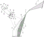
Fig. 1 is a conceptual diagram of an illustrative cardiac treatment system including an intracardiac medical device implanted in a patient's heart and a separate medical device positioned outside the patient's heart for use with the illustrative methods of, for example, fig. 16-18.
Fig. 2-4 are conceptual diagrams of an illustrative cardiac treatment system including a medical device including a lead having an electrode implanted in a patient's heart for use with the illustrative method of, for example, fig. 16-18.
Fig. 5 is an enlarged conceptual view of the intracardiac medical device of fig. 1 and the anatomy of the patient's heart.
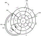
Fig. 6 is a conceptual diagram of a patient's heart in a standard 17-segment view of the left ventricle showing various electrode implantation locations for use with the exemplary systems and devices of fig. 1-4, for example.
Fig. 7 is a perspective view of an intracardiac medical device having a distal fixation and electrode assembly including a distal shell-based electrode implemented as a ring electrode for use with, for example, the illustrative systems and devices of fig. 1-4.
Fig. 8 is a block diagram of illustrative circuitry that may be enclosed within, for example, the housing of the medical device of fig. 1-4 to provide the functionality and treatment described herein.
Fig. 9 is a perspective view of another illustrative intracardiac medical device for use with, for example, the illustrative systems and devices of fig. 1-4.
Fig. 10 is a flow diagram of an illustrative method for detecting atrial activity using an atrial motion detector for use with the illustrative systems and devices of fig. 1-4, for example.
Fig. 11 is a flow diagram of an illustrative method for detecting heart sounds representing physiological response information for use with, for example, the illustrative systems and devices of fig. 1-4.
Fig. 12 is a flow diagram of an illustrative method of detecting bio-impedance for representing physiological response information for use with, for example, the illustrative systems and devices of fig. 1-4.
FIG. 13 is a diagram of an illustrative system including an electrode device, a display device, and a computing device for use with, for example, the illustrative systems and apparatus of FIGS. 1-4.
Fig. 14-15 are illustrations of illustrative external electrode devices for measuring torso-surface potentials for use with, for example, the illustrative systems and apparatus of fig. 1-4.
Fig. 16 is a conceptual diagram of an illustrative method for cardiac therapy for use with illustrative systems and devices such as fig. 1-4 and 13-15.
Fig. 17 is a conceptual diagram of an illustrative method for calibrating pacing therapy for use with illustrative systems and devices, such as fig. 1-4 and 13-15.
Fig. 18 is a conceptual diagram of an illustrative method for delivering pacing therapy for use with illustrative systems and devices, such as fig. 1-4 and 13-15.
Detailed Description
The technology of the present disclosure relates generally to implantable medical devices, systems, and methods for adaptive atrial-ventricular (VfA) cardiac therapy including single or multi-chamber pacing (e.g., dual or triple chamber pacing), atrioventricular synchronous pacing, asynchronous pacing, triggered pacing, cardiac resynchronization pacing, or tachycardia-related therapy. Although reference is made herein to an implantable medical device, such as a pacemaker or ICD, the methods and processes may be used with any medical device, system or method associated with a patient's heart. Various other applications will become apparent to those skilled in the art having the benefit of this disclosure.
It may be beneficial to provide an implantable medical device that does not contain a transvenous lead (e.g., a leadless device). It may also be beneficial to provide an implantable medical device that can be used for various cardiac therapies, such as single or multi-chamber pacing (e.g., dual or triple chamber pacing), atrioventricular synchronous pacing, asynchronous pacing, triggered pacing, cardiac resynchronization pacing, or tachycardia-related therapies. Further, it may be beneficial to provide a system that is capable of communicating with a separate medical device to provide triggered pacing or to provide shock therapy, for example, in the event of certain tachycardias. Still further, it may be beneficial to configure an implantable medical device to provide adaptive pacing therapy using only an intracardiac device or in conjunction with one or more leads or a separate medical device (e.g., an ECG strip).
The present disclosure provides an implantable medical device comprising a tissue-piercing electrode and optionally a right atrial electrode and/or a right atrial motion detector. The implantable medical device may be an VfA device implanted from the right atrium into the left ventricular muscle. The implantable medical device may be used, for example, to adapt adaptive cardiac therapy for pacing delays based at least on a measured heart rate. Physiological response measurements may be made, and the VfA device may be configured to deliver cardiac therapy based on the physiological response information. Specifically, the VfA device may be configured to adapt pacing therapy based on different heart rates, for example, by determining and delivering pacing therapy with an optimal Atrioventricular (AV) pacing delay. Advantageously, in one or more embodiments, the techniques of the present disclosure may be used to calibrate or deliver pacing therapy without using monitored electrical activity of the right ventricle of the patient's heart.
The tissue-piercing electrode may be implanted from the Koch triangle region of the right atrium through the right atrial endocardium and central fibrous body into the fundus and/or septal region of the left ventricular muscle of the patient's heart. In a leadless implantable medical device, a tissue-piercing electrode may extend leadless from a distal end region of a housing of the device, and a right atrial electrode may be leadless coupled to the housing (e.g., a portion of the housing or positioned on an exterior of the housing). The right atrial motion detector may be located within an implantable medical device. In a leaded implantable medical device, one or more of the electrodes may be coupled to the housing using an implantable lead. When the device is implanted, the electrodes may be used to sense electrical activity in one or more atria and/or ventricles of the patient's heart. The motion detector may be used to sense mechanical activity of one or more atria and/or ventricles of the patient's heart. In particular, the activity of the right atrium and left ventricle, and optionally, the activity of the right ventricle, may be monitored. The electrodes may be used to deliver cardiac therapy such as single chamber pacing for atrial fibrillation, atrioventricular synchronous pacing for bradycardia, asynchronous pacing, triggered pacing, cardiac resynchronization pacing for ventricular asynchrony, anti-tachycardia pacing, or shock therapy. Shock therapy may be initiated by the implanted medical device. A separate medical device, such as an extravascular ICD, that may also be implanted, may be in operative communication with the implanted medical device and may deliver a shock in response to a trigger, such as a signaling pulse (e.g., trigger, signaling, or unique electrical pulse) provided by the device.
Fig. 1-4 illustrate examples of various cardiac therapy systems that may be configured for use with methods such as those shown in fig. 16-18, for example, to calibrate and deliver pacing therapy based at least on a measured heart rate. Although the present disclosure describes leadless and leaded implantable medical devices, reference is first made to fig. 1 which shows a conceptual diagram of a cardiac therapy system 2 containing an intracardiac medical device 10 that may be configured for single or dual chamber therapy and implanted in a patient's heart 8. In some embodiments, device 10 may be configured for single chamber pacing, and may switch, for example, between single chamber pacing and multi-chamber pacing (e.g., dual chamber or triple chamber pacing). As used herein, "intracardiac" refers to a device configured to be implanted entirely within a patient's heart, for example, to provide cardiac therapy. There is shown a device 10 implanted in a target implant region 4 of the Right Atrium (RA) of a heart 8 of a patient. The device 10 may include one or more fixation members 20 that anchor the distal end of the device to the atrial endocardium in the target implant region 4. The target implant region 4 may be located between the his bundle 5 and the coronary sinus 3, and may be adjacent to the tricuspid valve 6. The device 10 may be described as an atrial-ventricular (VfA) device, which VfA device may sense or provide therapy to one or both ventricles (e.g., right ventricle, left ventricle, or both, depending on the situation) while generally positioned in the right atrium. In particular, the device 10 may comprise a tissue-piercing electrode that may be implanted from the Koch triangle region of the right atrium through the right atrial endocardium and central fibrous body into the fundus and/or septal region of the left ventricular muscle of the patient's heart.
The device 10 may be described as a leadless implantable medical device. As used herein, "leadless" refers to a device without leads extending from the patient's heart 8. In other words, the lead of the leadless device may not extend from outside the patient's heart to inside the patient's heart. Some leadless devices may be introduced through a vein, but once implanted, the devices do not or may not contain any transvenous leads and may be configured to provide cardiac therapy without the use of any transvenous leads. Further, leadless VfA devices, in particular, do not use leads to operatively connect to electrodes in the ventricle when the housing of the device is positioned in the atrium. In addition, the leadless electrode may be coupled to a housing of the medical device without the use of leads between the electrode and the housing.
The device 10 may include a dart electrode assembly 12 that defines or has a straight axis extending from a distal end region of the device 10. The dart electrode assembly 12 can pass through the atrial muscle and central fibrous body and into the ventricular muscle 14 or be placed along the ventricular septum, or at least be configured to pass through the atrial muscle and central fibrous body and into the ventricular muscle or be placed along the ventricular septum, without completely penetrating the ventricular endocardial or epicardial surface. The dart electrode assembly 12 may carry or include an electrode at a distal end region of the shaft such that the electrode may be positioned within the ventricular muscle to sense ventricular signals and deliver ventricular pulses (e.g., depolarize the left ventricle to initiate contraction of the left ventricle). In some examples, the electrode at the distal end region of the shaft is a cathode electrode of a bipolar electrode pair provided for pacing and sensing. While the illustrated implant region 4 may enable one or more electrodes of the dart electrode assembly 12 to be positioned in ventricular muscle, it has been recognized that devices having aspects disclosed herein may be implanted in other locations for multi-chamber pacing (e.g., dual or triple chamber pacing), single chamber pacing with multi-chamber sensing, single chamber pacing and/or sensing, or other suitable clinical treatments and applications.
It should be understood that although the device 10 is described herein as including a single dart electrode assembly, the device 10 may include more than one dart electrode assembly that passes through the atrial muscle and central fibrous body and into the ventricular muscle 14 or is placed along the ventricular septum, or is configured to pass through the atrial muscle and central fibrous body and into the ventricular muscle or along the ventricular septum, without completely penetrating the ventricular endocardial or epicardial surfaces. In addition, each dart electrode assembly may carry or include more than one electrode at a distal end region of the shaft or along other regions of the shaft (e.g., a proximal region or a central region).
The cardiac therapy system 2 may also include a separate medical device 50 (schematically depicted in fig. 1) that may be positioned external (e.g., subcutaneously) to the patient's heart 8 and that may be operably coupled to the patient's heart 8 to deliver cardiac therapy thereto. In one example, the individual medical device 50 may be an extravascular ICD. In some embodiments, an extravascular ICD may include a defibrillation lead that includes or carries a defibrillation electrode. A therapy vector may be present between the defibrillation electrode on the defibrillation lead and the housing electrode of the ICD. Further, one or more electrodes of the ICD may also be used to sense electrical signals associated with the heart 8 of the patient. The ICD may be configured to deliver shock therapy including one or more defibrillation or cardioversion shocks. For example, if an arrhythmia is sensed, the ICD may send pulses through the electrical lead to shock the heart and restore its normal rhythm. In some instances, ICDs may deliver shock therapy without placing electrical leads within the heart or attaching wires directly to the heart (subcutaneous ICDs). An example of an extravascular subcutaneous ICD that may be used with the system 2 described herein may be described in U.S. patent No. 9,278,229 issued on 8/3/2016 (Reinke et al), which is incorporated herein by reference in its entirety.
In the case of shock therapy (e.g., a defibrillation shock provided by a defibrillation electrode of a defibrillation lead), the individual medical device 50 (e.g., an extravascular ICD) may include control circuitry that uses therapy delivery circuitry to generate a defibrillation shock having any one of a variety of waveform characteristics, including leading edge voltage, slope, delivered energy, pulse phase, etc. The therapy delivery circuit may, for example, generate monophasic, biphasic, or multiphasic waveforms. In addition, the therapy delivery circuit may generate defibrillation waveforms having different amounts of energy. For example, the therapy delivery circuit may generate a defibrillation waveform that delivers a total of between approximately 60-80 joules (J) of energy for subcutaneous defibrillation.
The separate medical device 50 may further include sensing circuitry. The sensing circuitry may be configured to obtain electrical signals sensed by one or more combinations of the electrodes, and to process the obtained signals. The components of the sensing circuit may include analog components, digital components, or a combination thereof. The sensing circuit may, for example, include one or more sense amplifiers, filters, rectifiers, threshold detectors, analog-to-digital converters (ADCs), and the like. The sensing circuitry may convert the sensed signals to digital form and provide the digital signals to the control circuitry for processing and/or analysis. For example, the sensing circuit may amplify a signal from the sensing electrode and convert the amplified signal to a multi-bit digital signal through the ADC and then provide the digital signal to the control circuit. In one or more embodiments, the sensing circuitry may also compare the processed signal to a threshold to detect the presence of atrial or ventricular depolarization (e.g., P-waves or R-waves) and indicate the presence of atrial depolarization (e.g., P-waves) or ventricular depolarization (e.g., R-waves) to the control circuitry.
The device 10 and the separate medical device 50 may cooperate to provide cardiac therapy to the patient's heart 8. For example, the device 10 and the separate medical device 50 may be used to detect tachycardia, monitor tachycardia, and/or provide tachycardia-related therapy. For example, the device 10 may wirelessly communicate with the separate medical device 50 to trigger shock therapy using the separate medical device 50. As used herein, "wireless" refers to an operative coupling or connection between the device 10 and the separate medical device 50 that does not use metallic conductors. In one example, the wireless communication may use a unique, signaling or triggering electrical pulse provided by the device 10 that is conducted through the patient's tissue and detectable by the separate medical device 50. In another example, the wireless communication may use a communication interface (e.g., an antenna) of the device 10 to provide electromagnetic radiation that propagates through the patient's tissue and may be detected, for example, using a communication interface (e.g., an antenna) of the separate medical device 50.
Referring to fig. 2, the leaded medical device 408 includes one or a single implantable lead 410 having a tissue-piercing electrode assembly 12 coupled with a distal end region of the lead and implanted within the patient's heart 8. The housing 420 of the leaded medical device 408 may be implanted and positioned external to the patient's heart 8 and configured to calibrate the pacing therapy and/or deliver the pacing therapy, e.g., based at least on a measured heart rate. Lead 410 may contain a right atrial electrode and device 408 may operate as a device with dual channel capabilities (e.g., pacing and/or sensing in the right atrium and left ventricle). In some embodiments, lead 410 may not include a right atrial electrode. In other words, the leaded medical device 408 may be a single channel device that may be used for asynchronous, triggered, or other types of single channel pacing. When tissue-piercing electrode assembly 12 is implanted, for example, in the same or similar manner as described with respect to fig. 1, using lead 410, leaded medical device 408 may sense activity or deliver pacing to the Left Ventricle (LV).
Referring to fig. 3, a leaded medical device 418 is similar to the leaded medical device 408 of fig. 2, except that the device 418 includes two implantable leads 410, 412. In particular, implantable lead 412 can include an electrode (e.g., a right atrial electrode) coupled to a distal end region of lead 412, and can be implanted in a different location than lead 410. In some embodiments, lead 412 is implanted in a different region of the right atrium. In some embodiments, each lead 410, 412 may contribute one channel of a dual channel device 418. For example, when the tissue-piercing electrodes of tissue-piercing electrode assembly 12 are implanted, e.g., in the same or similar manner as described with respect to fig. 1, lead 410 may sense activity or deliver pacing to the Left Ventricle (LV), and lead 412 may sense activity or deliver pacing to the Right Atrium (RA).
Referring to fig. 4, a leaded medical device 428 is similar to the leaded medical device 418 of fig. 3, except that the device 428 includes three implantable leads 410, 412, 414. In particular, implantable lead 414 can include an electrode (e.g., a right ventricular electrode) coupled to a distal end region of lead 414 and can be implanted in a different location than leads 410, 412. In some embodiments, lead 414 is implanted in a region of the right ventricle. In some embodiments, each lead 410, 412, 414 may contribute one channel to the multi-channel device 428. For example, when tissue-piercing electrode assembly 12 is implanted, e.g., in the same or similar manner as described with respect to fig. 1, lead 410 may sense activity or deliver pacing to the Left Ventricle (LV), lead 412 may sense activity or deliver pacing to the Right Atrium (RA), and lead 414 may sense activity or deliver pacing to the Right Ventricle (RV).
In some embodiments, a pacing delay (e.g., RV-LV pacing delay, or more generally, VV pacing delay) between an RV electrode on lead 414 for pacing the RV and an LV electrode on lead 410 for pacing the LV may be calibrated or optimized, for example, using a separate medical device, such as an electrode device (e.g., an ECG strip). Various methods may be used to calibrate or optimize the VV delay. In some embodiments, medical device 428 may be used to test pacing at a plurality of different VV delays. For example, the RV may pace about 80, 60, 40, and 20 milliseconds (ms) earlier than the LV, and the LV may pace about 80, 60, 40, and 20 ms earlier than the RV, as well as RV-LV concurrent pacing (e.g., about 0 ms VV pacing delay). The medical apparatus 428 may then, for example, be configured to automatically select a VV pacing delay that, when used for pacing, corresponds to a minimum electrical dyssynchrony measured using the electrode device. Test pacing at different VV pacing delays may be performed using a particular AV delay (e.g., a nominal AV delay set by medical device 428) or at a predetermined optimal AV delay based on patient characteristics.
Fig. 5 is an enlarged conceptual view of the endocardial medical device 10 of fig. 1 and the anatomy of the patient's heart 8. In particular, device 10 is configured to conduct and/or deliver pacing therapy based, for example, on at least a measured heart rate. The intracardiac device 10 may comprise a housing 30. Housing 30 may define a hermetically sealed internal cavity in which the internal components of device 10 (e.g., sensing circuitry, therapy delivery circuitry, control circuitry, memory, telemetry circuitry, other optional sensors, and a power source, as generally described in connection with fig. 8) reside. The housing 30 may be formed of an electrically conductive material comprising titanium or a titanium alloy, stainless steel, MP35N (a non-magnetic nickel-cobalt-chromium-molybdenum alloy), a platinum alloy, or other biocompatible metal or metal alloy. In other examples, the housing 30 may be formed of a non-conductive material including ceramic, glass, sapphire, silicone, polyurethane, epoxy, acetyl copolymer plastic, Polyetheretherketone (PEEK), liquid crystal polymer, or other biocompatible polymers.
In at least one embodiment, the housing 30 can be described as extending in a generally cylindrical shape between the distal end region 32 and the proximal end region 34 to facilitate catheter delivery. In other embodiments, the housing 30 may be prismatic or any other shape to perform the functions and utilities described herein. The housing 30 may contain a delivery tool interface member 26, for example at the proximal end region 34, for engagement with a delivery tool during implantation of the device 10.
All or a portion of housing 30 may be used as an electrode during cardiac therapy, for example, in sensing and/or pacing. In the example shown, the housing-based electrode 24 is shown circumscribing a proximal portion of the housing 30 (e.g., closer to the proximal end region 34 than the distal end region 32). When housing 30 is formed of a conductive material (e.g., a titanium alloy or other examples listed above), portions of housing 30 may be electrically insulated by a non-conductive material (e.g., a coating of parylene, polyurethane, silicone, epoxy, or other biocompatible polymer) to expose one or more discrete regions of the conductive material to define proximal housing-based electrode 24. When housing 30 is formed of a non-conductive material, such as a ceramic, glass, or polymeric material, a conductive coating or layer, such as titanium, platinum, stainless steel, or alloys thereof, may be applied to one or more discrete regions of housing 30 to form proximal housing-based electrode 24. In other examples, proximal housing-based electrode 24 may be a component, such as a ring electrode, mounted or assembled to housing 30. Proximal housing-based electrode 24 may be electrically coupled to internal circuitry of device 10, for example, by a conductive housing 30 or by electrical conductors when housing 30 is a non-conductive material.
In the example shown, the proximal housing-based electrode 24 is positioned closer to the housing proximal end region 34 than the housing distal end region 32, and is therefore referred to as the "proximal housing-based electrode" 24. However, in other examples, housing-based electrode 24 may be positioned at other locations along housing 30, e.g., farther relative to the illustrated location.
At the distal end region 32, the device 10 may include a distal fixation and electrode assembly 36, which may include one or more fixation members 20 and one or more dart electrode assemblies 12 of equal or unequal length. In one example, a single dart electrode assembly 12 includes a shaft 40 extending distally from the housing distal end region 32 and one or more electrode elements, such as a tip electrode 42, at or near the free distal end region of the shaft 40. The tip electrode 42 may have a conical or hemispherical distal tip with a relatively narrow tip diameter (e.g., less than about 1 millimeter (mm)) for penetrating and penetrating tissue layers without the use of a sharp tip or needle-like tip with sharp or beveled edges.
The shaft 40 of the dart electrode assembly 12 may be a generally straight member and may be rigid. In other embodiments, the shaft 40 may be described as being relatively stiff, but still having limited flexibility in the lateral direction. Further, the shaft 40 may be non-rigid to allow some lateral bending to occur as the heart moves. However, in the relaxed state, when not subjected to any external forces, the shaft 40 may maintain a straight position as shown to space the tip electrode 42 from the housing distal end region 32 by at least the height 47 of the shaft 40. In other words, the dart electrode assembly 12 can be described as being elastic.
The dart electrode assembly 12 may be configured to pierce one or more tissue layers to position the tip electrode 42 in a desired tissue layer, such as in the ventricular muscle. As such, the height 47 or length of shaft 40 may correspond to the intended pacing site depth, and shaft 40 may have a relatively high compressive strength along its longitudinal axis to resist bending in a lateral or radial direction when pressed against implanted region 4. If the second dart electrode assembly 12 is employed, its length may not equal the expected pacing site depth and may be configured to act as an indifferent electrode for delivering pacing energy to tissue. A longitudinal axial force may be applied to the tip electrode 42, for example, by applying a longitudinal pushing force to the proximal end 34 of the housing 30, to advance the dart electrode assembly 12 into tissue within a target implant area. The shaft 40 may be described as being longitudinally non-compressible and/or elastically deformable in a lateral or radial direction when subjected to a lateral or radial force to allow, for example, temporary bending as tissue moves, but may return to its generally straight position when the lateral force is reduced. When the shaft 40 is not exposed to any external forces or is only exposed to forces along its longitudinal central axis, the shaft 40 may maintain a straight linear position as shown.
The one or more fixation members 20 can be described as one or more "tines" having a normal bent position. The tines may be held in a distally extending position within the delivery tool. The distal tip of the tines may penetrate heart tissue to a limited depth before resiliently flexing proximally back to the normal flexed position (as shown) when released from the delivery tool. Further, the fixation member 20 may include one or more aspects described, for example, in U.S. patent No. 9,675,579 issued on 6/13 of 2017 (Grubac et al) and U.S. patent No. 9,119,959 issued on 9/1 of 2015 (Rys et al), each of which is incorporated herein by reference in its entirety.
In some examples, the distal fixation and electrode assembly 36 includes a distal housing-based electrode 22. Where multi-lumen pacing (e.g., dual or triple lumen pacing) and sensing are performed using device 10 as a pacemaker, tip electrode 42 may serve as a cathode electrode paired with proximal housing-based electrode 24, which serves as a return anode electrode. Alternatively, the distal housing-based electrode 22 may serve as a return anode electrode paired with the tip electrode 42 for sensing ventricular signals and delivering ventricular pacing pulses. In other examples, distal housing-based electrode 22 may be a cathode electrode for sensing atrial signals and delivering pacing pulses to atrial muscles in target implant region 4. When the distal housing-based electrode 22 serves as an atrial cathode electrode, the proximal housing-based electrode 24 may serve as a return anode paired with the tip electrode 42 for ventricular pacing and sensing, and may serve as a return anode paired with the distal housing-based electrode 22 for atrial pacing and sensing.
As shown in this illustration, in some pacing applications, the target implant region 4 lies along the atrial endocardium 18, generally below the AV node 15 and his bundle 5. The dart electrode assembly 12 may at least partially define a height 47 or length of the axis 40 to pass through the atrial endocardium 18 in the target implant region 4, through the central fibrous body 16, and into the ventricular muscle 14 without penetrating the ventricular endocardial surface 17. When the height 47 or length of the dart electrode assembly 12 is fully advanced into the target implant region 4, the tip electrode 42 may be placed within the ventricular muscle 14 and the distal housing-based electrode 22 may be positioned in close contact or close proximity to the atrial endocardium 18. In various examples, the dart electrode assembly 12 may have a total combined height 47 or length of the tip electrode 42 and the shaft 40 of about 3mm to about 8 mm. The diameter of the shaft 40 may be less than about 2mm, and may be about 1mm or less, or even about 0.6mm or less.
The device 10 may contain an acoustic or motion detector 11 within the housing 30. The acoustic or motion detector 11 may be operatively coupled to one or more of the control circuitry 80 (fig. 8), the sensing circuitry 86 (fig. 8), or the therapy delivery circuitry 84 (fig. 8). In some embodiments, the acoustic or motion detector 11 may be used with the methods 600, 650, or 800 as shown in fig. 10-12. The acoustic or motion detector 11 may be used to monitor mechanical activity, such as atrial mechanical activity (e.g., atrial contractions) and/or ventricular mechanical activity (e.g., ventricular contractions). In some embodiments, an acoustic or motion detector 11 may be used to detect right atrial mechanical activity. Non-limiting examples of acoustic or motion detectors 11 include accelerometers or microphones. In some embodiments, mechanical activity detected by acoustic or motion detector 11 may be used to supplement or replace electrical activity detected by one or more of the electrodes of apparatus 10. For example, acoustic or motion detectors 11 may be used in addition to or as an alternative to the proximal housing-based electrodes 24.
The acoustic or motion detector 11 may also be used for rate-responsive detection or to provide a rate-responsive IMD. Various techniques related to rate response may be described below: U.S. patent No. 5,154,170 entitled "Optimization of rate-responsive cardiac pacemaker (Bennett et al), issued on 13.10.1992, and U.S. patent No. 5,562,711 entitled" Method and apparatus for rate-responsive cardiac pacing "(Yerich et al), issued on 8.10.1996, each of which is incorporated herein by reference in its entirety.
In various embodiments, the acoustic or motion sensor 11 may be used as an HS sensor and may be implemented as a microphone or a 1-, 2-, or 3-axis accelerometer. In one embodiment, the acoustic sensor is implemented as a piezoelectric crystal mounted within the implantable medical device housing and responsive to mechanical motion associated with heart sounds. The piezoelectric crystal may be a dedicated HS sensor, or may be used for multiple functions. In the illustrative embodiment shown, the acoustic sensor is embodied in the form of a piezoelectric crystal that is also used to generate a patient alert signal in the form of a detectable vibration of the IMD housing. Upon detection of an alarm condition, the control circuitry 80 may cause the patient alarm control circuitry to generate an alarm signal by activating the piezoelectric crystal.
The control circuitry may be used to control whether the piezoelectric crystal is used in a "listening mode" to sense HS signals through the HS sensing circuitry, or in an "output mode" to generate a patient alarm. During patient alarm generation, the HS sensing circuitry may be temporarily decoupled from the HS sensor by the control circuitry.
Examples of other embodiments of acoustic sensors that may be suitable for implementation with the techniques of this disclosure may be generally described in U.S. patent No. 4,546,777 (Groch et al), U.S. patent No. 6,869,404 (schuhauser et al), U.S. patent No. 5,554,177 (Kieval et al), and U.S. patent No. 7,035,684 (Lee et al), each of which is incorporated herein by reference in its entirety.
Various types of acoustic sensors may be used. The acoustic sensor may be any implantable or external sensor that is responsive to one or more of the heart sounds generated as previously described, and thereby generates an electrical analog signal that is correlated in time and amplitude to the heart sounds. The analog signal may then be processed by the HS sensing module (which may include digital conversion) to obtain HS parameters, such as amplitude or relative time interval, derived by the HS sensing module or control circuit 80. The acoustic sensor and HS sensing module may be incorporated into an IMD capable of delivering CRT or another cardiac therapy being optimized, or may be implemented in a separate device in wired or wireless communication with the IMD or in an external programmer or computer used during a pacing parameter optimization procedure as described herein.
Fig. 6 is a two-dimensional (2D) ventricular map 300 (e.g., top view) of a patient's heart showing a left ventricle 320 and a right ventricle 322 in a standard 17-segment view. The diagram 300 includes a plurality of regions 326 corresponding to different regions of a human heart. As shown, region 326 is numerically labeled 1-17 (e.g., it corresponds to a standard 17-segment model of a human heart, to a 17-segment model of the left ventricle of a human heart, etc.). Region 326 of figure 300 can include a base forward region 1, a base forward spacer region 2, a base lower spacer region 3, a base lower region 4, a base lower region 5, a base forward region 6, a mid forward region 7, a mid forward spacer region 8, a mid lower spacer region 9, a mid lower region 10, a mid lower region 11, a mid forward region 12, a top forward region 13, a top spacer region 14, a top lower region 15, a top side region 16, and a top region 17. The inferior and anterior septal regions of the right ventricle 322 are also shown, as well as the right and left bundle branches (RBB, LBB).
In some embodiments, any of the tissue-piercing electrodes of the present disclosure may be implanted in the fundus and/or spacer region of the left ventricular muscle of the patient's heart. In particular, the tissue-piercing electrode may be implanted from the Koch triangle region of the right atrium through the right atrial endocardium and central fibrous body.
Once implanted, the tissue-piercing electrodes may be positioned in a target implant region 4 (fig. 1-5), such as the fundus and/or septal region of the left ventricular muscle. Referring to fig. 300, the base region includes one or more of a base front region 1, a base front spacer region 2, a base lower spacer region 3, a base lower region 4, a middle front region 7, a middle front spacer region 8, a middle lower spacer region 9, and a middle lower region 10. Referring to diagram 300, the spacer region includes one or more of the basal protospacer 2, the basal protospacer 3, the middle protospacer 8, the middle lower spacer 9, and the top spacer 14.
In some embodiments, when implanted, the tissue-piercing electrode may be positioned in the basal septal region of the left ventricular muscle. The substrate spacer region may include one or more of a substrate spacer 2, a substrate lower spacer 3, a middle pre-spacer 8, and a middle lower spacer 9.
In some embodiments, when implanted, the tissue-piercing electrode may be positioned in the inferior-superior/posterior basal septal region of the left ventricular muscle. The superior/posterior basal septal region of the left ventricular muscle can comprise a portion of one or more of the basal and inferior septal regions 3 and 9 (e.g., only the basal and inferior septal regions, only the medial and inferior septal regions, or both). For example, the sub-elevation/sub-base spacing region may include a region 324 generally illustrated as a dashed line boundary. As shown, the dashed boundary represents an approximate form of where the sub-elevation/sub-elevation substrate spacing region is located, which may vary slightly in shape or size depending on the particular application.
Fig. 7 is a three-dimensional perspective view of device 10 capable of calibrating and/or delivering pacing therapy, e.g., based at least on a measured heart rate. As shown, the distal fixation and electrode assembly 36 includes a distal housing-based electrode 22 implemented as a ring electrode. When the fixation member tines 20a, 20b, and 20c of the fixation member 20 engage the atrial tissue, the distal housing-based electrode 22 may be positioned in close contact with or in operative proximity to the atrial tissue. The resiliently deformable tines 20a, 20b, and 20c can extend distally during delivery of the device 10 to the implantation site. For example, the tines 20a, 20b, and 20c can pierce the atrial endocardial surface when the device 10 is ejected from the delivery tool and bend back to its normal bent position (as shown) when no longer constrained within the delivery tool. When the tines 20a, 20b, and 20c are flexed back to their normal positions, the fixation member 20 can pull the distal fixation member and electrode assembly 36 against the atrial endocardial surface. As the distal fixation member and electrode assembly 36 is pulled against the atrial endocardium, the tip electrode 42 may be advanced through the atrial muscle and the central fibrous body and into the ventricular muscle. The distal housing-based electrode 22 may then be positioned on the atrial endocardial surface.
The distal housing-based electrode 22 may comprise a ring formed of an electrically conductive material, such as titanium, platinum, iridium, or alloys thereof. The distal housing-based electrode 22 may be a single continuous ring electrode. In other examples, portions of the ring may be coated with an electrically insulating coating, such as parylene, polyurethane, silicone, epoxy, or other insulating coating, to reduce the conductive surface area of the ring electrode. For example, one or more sectors of the ring may be coated to separate two or more electrically conductive exposed surface areas of the distal housing-based electrode 22. Reducing the conductive surface area of the distal housing-based electrode 22, for example, by covering portions of the conductive ring with an insulating coating, may increase the electrical impedance of the distal housing-based electrode 22 and thereby reduce the current delivered during a pacing pulse that captures the myocardium (e.g., atrial musculature). The lower current consumption may conserve power of the device 10, such as one or more rechargeable or non-rechargeable batteries.
As described above, the distal housing-based electrode 22 may be configured as an atrial cathode electrode for delivering pacing pulses to atrial tissue at the implant site in conjunction with the proximal housing-based electrode 24 as a return anode. Electrodes 22 and 24 may be used to sense atrial P-waves, for controlling atrial pacing pulses (delivered in the absence of sensed P-waves) and for controlling atrial-synchronized ventricular pacing pulses delivered using tip electrode 42 as a cathode and proximal housing-based electrode 24 as a return anode. In other examples, the distal housing-based electrode 22 may be used as a return anode in conjunction with a cathode tip electrode 42 for ventricular pacing and sensing.
Fig. 8 is a block diagram of circuitry that may be enclosed within housing 30 (fig. 7) to provide functionality to calibrate pacing therapy and/or deliver pacing therapy using device 10 according to one example, e.g., based at least on a measured heart rate, or within the housing of any other medical device described herein (e.g., device 408 of fig. 2, device 418 of fig. 3, device 428 of fig. 4, or device 710 of fig. 9). An individual medical device 50 (fig. 1-4) may contain some or all of the same components, which may be configured in a similar manner. The electronic circuitry enclosed within the housing 30 may contain software, firmware, and hardware that cooperatively monitor atrial and ventricular cardiac electrical signals, determine when cardiac therapy is needed, and/or deliver electrical pulses to the patient's heart according to programmed therapy patterns and pulse control parameters. The electronic circuitry may include control circuitry 80 (e.g., including processing circuitry), memory 82, therapy delivery circuitry 84, sensing circuitry 86, and/or telemetry circuitry 88. In some examples, device 10 includes one or more sensors 90 (such as patient activity sensors) for generating signals related to a physiological function, state, or condition of the patient for determining a need for pacing therapy and/or controlling a pacing rate. For example, one sensor 90 may comprise an inertial measurement unit (e.g., an accelerometer) for measuring motion.
The power supply 98 may provide power to the circuitry of the apparatus 10 including each of the components 80, 82, 84, 86, 88, 90 as needed. Power source 98 may include one or more energy storage devices, such as one or more rechargeable or non-rechargeable batteries. The connections (not shown) between the power supply 98 and each of the components 80, 82, 84, 86, 88, 90 may be understood from general block diagrams shown to those of ordinary skill in the art. For example, power supply 98 may be coupled to one or more charging circuits included in therapy delivery circuitry 84 for providing power for charging retention capacitors included in therapy delivery circuitry 84 that discharge at appropriate times under control of control circuitry 80 to deliver pacing pulses, e.g., according to a dual chamber pacing mode such as ddi (r). The power supply 98 may also be coupled to components of the sensing circuitry 86 (e.g., sense amplifiers, analog-to-digital converters, switching circuitry, etc.), the sensor 90, the telemetry circuitry 88, and the memory 82 to provide power to the various circuits.
The functional blocks shown represent functions included in the device 10 and may comprise any discrete and/or integrated electronic circuit components implementing analog and/or digital circuits capable of producing the functions attributed to the medical device 10 herein. Various components may comprise processing circuitry (e.g., an Application Specific Integrated Circuit (ASIC), an electronic circuit, a processor (shared, dedicated, or group) and memory) that executes one or more software or firmware programs, a combinational logic circuit, a state machine, or other suitable components or combinations of components that provide the described functionality. The particular form of software, hardware, and/or firmware used to implement the functions disclosed herein will be determined primarily by the particular system architecture employed in the medical device and the particular detection and therapy delivery methods employed by the medical device.
The memory 82 may comprise any volatile, non-volatile, magnetic, or electrically non-transitory computer-readable storage medium, such as Random Access Memory (RAM), Read Only Memory (ROM), non-volatile RAM (nvram), electrically erasable programmable ROM (eeprom), flash memory, or any other memory device. Further, memory 82 may include a non-transitory computer-readable medium storing instructions that, when executed by the one or more processing circuits, cause control circuitry 80 and/or other processing circuitry to calibrate the pacing therapy and/or perform single-, dual-or triple-chamber calibrated pacing therapy (e.g., single-chamber or multi-chamber pacing) or other cardiac therapy functions attributed to device 10 (e.g., sensing or delivering therapy). The non-transitory computer readable medium storing the instructions may include any of the media listed above.
The control circuitry 80 may communicate with the therapy delivery circuitry 84 and the sensing circuitry 86, e.g., over a data bus, to sense cardiac electrical signals and control delivery of cardiac electrical stimulation therapy in response to sensed cardiac events (e.g., P-waves and R-waves, or the absence thereof). Tip electrode 42, distal shell-based electrode 22, and proximal shell-based electrode 24 may be electrically coupled to therapy delivery circuitry 84 for delivering electrical stimulation pulses to the patient's heart, and to sensing circuitry 86 for sensing cardiac electrical signals.
Each of atrial sensing channel 87 and ventricular sensing channel 89 may contain cardiac event detection circuitry for detecting P-waves and R-waves, respectively, from cardiac electrical signals received by the respective sensing channel. The cardiac event detection circuitry contained in each of channels 87 and 89 may be configured to amplify, filter, digitize, and rectify cardiac electrical signals received from selected electrodes to improve signal quality for detecting cardiac electrical events. The cardiac event detection circuitry within each channel 87 and 89 may include one or more sense amplifiers, filters, rectifiers, threshold detectors, comparators, analog-to-digital converters (ADCs), timers, or other analog or digital components. Cardiac event sensing thresholds, such as P-wave sensing thresholds and R-wave sensing thresholds, may be automatically adjusted by each respective sensing channel 87 and 89 under the control of control circuit 80, e.g., based on timing intervals and sensing thresholds determined by control circuit 80 that are stored in memory 82 and/or controlled by hardware, firmware, and/or software of control circuit 80 and/or sensing circuit 86.
Upon detecting a cardiac electrical event based on a sensing threshold crossing, the sensing circuitry 86 may generate a sensed event signal that is communicated to the control circuitry 80. For example, atrial sensing channel 87 may generate a P-wave sensed event signal in response to a P-wave sensing threshold crossing. Ventricular sensing channel 89 may generate an R-wave sensed event signal in response to the R-wave sensing threshold crossing. The control circuit 80 may use the sensed event signals to set a pace escape interval timer that controls the base time interval for scheduling cardiac pacing pulses. The sensed event signals may trigger or inhibit a pacing pulse depending on the particular programmed pacing mode. For example, a P-wave sensed event signal received from atrial sensing channel 87 may cause control circuit 80 to suppress a scheduled atrial pacing pulse and schedule a ventricular pacing pulse at a programmed Atrioventricular (AV) pacing interval. If an R-wave is sensed before the AV pacing interval expires, the ventricular pacing pulse may be suppressed. If the AV pacing interval expires before control circuit 80 receives an R-wave sensed event signal from ventricular sensing channel 89, control circuit 80 may deliver a scheduled ventricular pacing pulse synchronized to the sensed P-wave using therapy delivery circuit 84.
In some instances, device 10 may be configured to deliver various pacing therapies, including bradycardia pacing, cardiac resynchronization therapy, post-shock pacing, and/or tachycardia related therapies, such as ATP and the like. For example, device 10 may be configured to detect non-sinus tachycardia and deliver ATP. Control circuitry 80 may determine cardiac event time intervals, such as P-P intervals between successive P-wave sensed event signals received from atrial sensing channel 87, R-R intervals between successive R-wave sensed event signals received from ventricular sensing channel 89, and P-R and/or R-P intervals received between P-wave sensed event signals and R-wave sensed event signals. These intervals may be compared to tachycardia detection intervals to detect non-sinus tachycardias. Tachycardia can be detected in a given heart chamber based on a threshold number of tachycardia detection intervals detected.
The holding capacitors of the atrial or ventricular pacing circuits 83, 85 may be charged to the programmed pacing voltage amplitude and discharged for the programmed pacing pulse width by the therapy delivery circuit 84 according to control signals received from the control circuit 80. For example, the pacing timing circuitry included in control circuitry 80 may include programmable digital counters set by the microprocessor of control circuitry 80 for controlling the basic pacing time intervals associated with various single or multi-chamber pacing (e.g., dual or triple chamber pacing) modes or anti-tachycardia pacing sequences. The microprocessor of control circuit 80 may also set the amplitude, pulse width, polarity, or other characteristic of the cardiac pacing pulses, which may be based on programmed values stored in memory 82.
The device 10 may include other sensors 90 for sensing signals from the patient for determining the need for and/or controlling the electrical stimulation therapy delivered by the therapy delivery circuitry 84. In some examples, the sensor indicating a need for increased cardiac output may include a patient activity sensor, such as an accelerometer. An increase in the metabolic demand of the patient due to an increase in activity as indicated by the patient activity sensor may be determined by the control circuitry 80 for use in determining the pacing rate indicated by the sensor. The control circuitry 80 may be used to calibrate and/or deliver pacing therapy based on a patient activity sensor (e.g., a measured heart rate).
Control parameters utilized by control circuit 80 for sensing cardiac events and controlling the delivery of pacing therapy may be programmed into memory 82 through telemetry circuit 88, which may also be described as a communication interface. The telemetry circuit 88 includes a transceiver and antenna for communicating with an external device, such as a programmer or home detector, using radio frequency communication or other communication protocols. Control circuitry 80 may receive downlink telemetry from an external device and transmit uplink telemetry to the external device using telemetry circuitry 88. In some cases, the telemetry circuitry 88 may be used to transmit and receive communication signals to/from another medical device implanted in the patient.
Fig. 9 is a three-dimensional perspective view of another leadless intracardiac medical device 710 that may be configured to calibrate and/or deliver pacing therapy, e.g., based at least on a measured heart rate, for single or multi-chamber cardiac therapy (e.g., dual or triple chamber cardiac therapy), according to another example. Device 710 may include a housing 730 having an outer sidewall 735, shown as a cylindrical outer sidewall, extending from a housing distal end region 732 to a housing proximal end region 734. The housing 730 may enclose electronic circuitry configured to perform single or multi-chamber cardiac therapies, including atrial and ventricular cardiac electrical signal sensing and pacing of the atrial and ventricular chambers. The delivery tool interface member 726 is shown on the housing proximal end region 734.
A distal fixation and electrode assembly 736 can be coupled to the housing distal end region 732. The distal fixation and electrode assembly 736 can include an electrically insulative distal member 772 coupled to the housing distal end region 732. The tissue-piercing electrode assembly 712 extends away from the housing distal end region 732, and the plurality of non-tissue-piercing electrodes 722 can be directly coupled to an insulative distal member 772. Tissue-piercing electrode assembly 712 extends in a longitudinal direction away from housing distal end region 732 and may be coaxial with a longitudinal central axis 731 of housing 730.
Distal tissue-piercing electrode assembly 712 may include an electrically insulated shaft 740 and a tip electrode 742 (e.g., a tissue-piercing electrode). In some examples, tissue-piercing electrode assembly 712 is a movable stationary member that includes a helical shaft 740 and a distal cathode tip electrode 742. The helical shaft 740 can extend from the shaft distal end region 743 to a shaft proximal end region 741, which can be directly coupled to the insulative distal member 772. Helical shaft 740 may be coated with an electrically insulating material, such as parylene or other examples listed herein, to avoid sensing or stimulating heart tissue along the length of the shaft. Tip electrode 742 is at shaft distal end region 743 and may serve as a cathode electrode for delivering ventricular pacing pulses and sensing ventricular electrical signals using proximal housing-based electrode 724 as a return anode when tip electrode 742 is advanced into ventricular tissue. Proximal housing-based electrode 724 may be an annular electrode circumscribing housing 730 and may be defined by uninsulated portions of longitudinal sidewall 735. Other portions of the housing 730 not acting as electrodes may be coated with an electrically insulating material as described above in connection with fig. 7.
The use of two or more tissue-piercing electrodes (e.g., any type of tissue-piercing electrode) that penetrate into the LV myocardium may be used for more localized pacing capture and may mitigate ventricular pacing spikes, thereby affecting capture of atrial tissue. In some embodiments, the plurality of tissue-piercing electrodes may include two or more dart-type electrode assemblies (e.g., electrode assembly 12 of fig. 7), helical-type electrodes (e.g., electrode assembly 712). Non-limiting examples of a plurality of tissue-piercing electrodes include two dart electrode assemblies, a spiral electrode having a dart electrode assembly extending therethrough (e.g., through the center), or a double-wound spiral. Multiple tissue-piercing electrodes may also be used for bipolar or multipolar pacing.
In some embodiments, one or more tissue-piercing electrodes (e.g., any type of tissue-piercing electrode) that penetrate into the LV myocardium may be multi-polar tissue-piercing electrodes. The multi-polar tissue-piercing electrode may include one or more electro-active elements and an electro-discrete element, which may enable bipolar or multi-polar pacing from the one or more tissue-piercing electrodes.
A plurality of non-tissue-piercing electrodes 722 can be provided along the outer periphery of the insulative distal member 772, which is located at the outer periphery of the tissue-piercing electrode assembly 712. The insulative distal member 772 can define a distal facing surface 738 of the device 710 and a circumferential surface 739 circumscribing the device 710 adjacent the housing longitudinal sidewall 735. Non-tissue-piercing electrode 722 may be formed from a conductive material such as titanium, platinum, iridium, or alloys thereof. In the illustrated embodiment, six non-tissue-piercing electrodes 722 are radially spaced apart at equal distances along the outer circumference of the insulative distal member 772, however, two or more non-tissue-piercing electrodes 722 may be provided.
The non-tissue-piercing electrodes 722 may be discrete components, each held within a corresponding recess 774 in the insulative member 772 that is sized and shaped to mate with the non-tissue-piercing electrodes 722. In other examples, the non-tissue-piercing electrodes 722 may each be an uninsulated exposed portion of a unitary member mounted within or on the insulative distal member 772. The intermediate portion of the monolithic member that is not used as an electrode may be insulated by the insulating distal member 772 or, if exposed to the surrounding environment, may be coated with an electrically insulating coating, such as parylene, polyurethane, silicone, epoxy, or other insulating coating.
As the tissue-piercing electrode assembly 712 is advanced into the cardiac tissue, the at least one non-tissue-piercing electrode 722 may be positioned against, in intimate contact with, or in operative proximity to the cardiac tissue surface to deliver pulses and/or sense cardiac electrical signals generated by the patient's heart. For example, when the tissue-piercing electrode assembly 712 is advanced into atrial tissue and through the central fibrous body until the distal tip electrode 742 is positioned in direct contact with ventricular tissue (e.g., ventricular muscle and/or a portion of the ventricular conduction system), the non-tissue-piercing electrode 722 may be positioned in contact with right atrial endocardial tissue for pacing and sensing in the atrium.
Non-tissue-piercing electrode 722 may be coupled to therapy delivery circuitry 84 and sensing circuitry 86 (see fig. 8) enclosed by housing 730 to function in conjunction with proximal housing-based electrode 724 as a return anode as a cathode electrode for delivering atrial pacing pulses and sensing atrial electrical signals (e.g., P-waves). Switching circuitry included in sensing circuitry 86 may be activated under the control of control circuitry 80 to couple one or more of the non-tissue-piercing electrodes to atrial sensing channel 87. Distal non-tissue-piercing electrodes 722 may be electrically isolated from one another such that each individual electrode of electrodes 722 may be individually selected by switching circuitry included in therapy delivery circuit 84 to act as an atrial cathode electrode, either individually or in combination with two or more of electrodes 722. Switching circuitry included in therapy delivery circuitry 84 may be activated under control of control circuitry 80 to couple one or more of non-tissue-piercing electrodes 722 to atrial pacing circuitry 83. Two or more of non-tissue-piercing electrodes 722 may be selected at a time to operate as a multi-point atrial cathode electrode.
Certain non-tissue-piercing electrodes 722 may be selected for atrial pacing and/or atrial sensing based on atrial capture threshold testing, electrode impedance, P-wave signal strength in cardiac electrical signals, or other factors. For example, a single non-tissue-piercing electrode 722, or any combination of two or more separate such non-tissue-piercing electrodes, that serves as a cathode electrode that provides the best combination of a low pacing capture threshold amplitude and a relatively high electrode impedance, may be selected to achieve reliable atrial pacing using minimal current consumption from power supply 98.
In some cases, distal-facing surface 738 can uniformly contact the atrial endocardial surface when tissue-piercing electrode assembly 712 anchors housing 730 at the implantation site. In such a case, all of the electrodes 722 may be selected together to form the atrial cathode. Alternatively, every other one of the electrodes 722 may be selected together to form a multi-point atrial cathode with higher electrical impedance, still evenly distributed along the distal-facing surface 738. Alternatively, a subset of one or more electrodes 722 along one side of the insulative distal member 772 may be selected to provide pacing at a desired site that achieves the lowest pacing capture threshold due to the relative position of the electrodes 722 with respect to the atrial tissue being paced.
In other instances, the distal-facing surface 738 may be oriented at an angle relative to the adjacent endocardial surface depending on the location and orientation of the tissue-piercing electrode assembly 712 into the cardiac tissue. In this case, one or more of the non-tissue-piercing electrodes 722 may be positioned in closer contact with adjacent endocardial tissue than other non-tissue-piercing electrodes 722, which may be angled away from the endocardial surface. By providing a plurality of non-tissue-piercing electrodes along the outer periphery of insulative distal member 772, the angle of tissue-piercing electrode assembly 712 and housing distal end region 732 relative to the surface of the heart (e.g., the right atrial endocardial surface) may not need to be substantially parallel. Differences in anatomy and positioning may angle or tilt the distal-facing surface 738 relative to the endocardial surface, however, the plurality of non-tissue-piercing electrodes 722 distributed along the outer periphery of the insulative distal member 772 increases the likelihood of good contact between the one or more electrodes 722 and adjacent cardiac tissue, thereby facilitating acceptable pacing thresholds and reliable cardiac event sensing using at least a subset of the plurality of electrodes 722. It may not be necessary to contact or secure circumferentially along the entire circumference of the insulative distal member 772.
Non-tissue-piercing electrodes 722 are shown as each including a first portion 722a extending along a distal-facing surface 738 and a second portion 722b extending along a circumferential surface 739. The first and second portions 722a, 722b can be continuous exposed surfaces such that the active electrode surface wraps over the outer peripheral edge 776 of the insulative distal member 772 that joins the distal facing surface 738 and the circumferential surface 739. The non-tissue-piercing electrodes 722 may include one or more of the electrodes 722 along the distal-facing surface 738, one or more electrodes along the circumferential surface 739, one or more electrodes each extending along both the distal-facing surface 738 and the circumferential surface 739, or any combination thereof. The exposed surface of each of the non-tissue-piercing electrodes 722 may be flush with the respective distal-facing surface 738 and/or the circumferential surface. In other examples, each of the non-tissue-piercing electrodes 722 may have a convex surface protruding from the insulative distal member 772. However, any convex surface of the electrode 722 may define a smooth or rounded non-tissue piercing surface.
The distal fixation and electrode assembly 736 can seal the distal end region of the housing 730 and can provide a basis on which to mount the electrode 722. Electrode 722 may be referred to as a housing-based electrode. The electrode 722 may not be carried by a shaft or other extension that extends the active electrode portion away from the housing 730 (e.g., a distal tip electrode 742 located at the distal tip of a helical shaft 740 extending away from the housing 730). Other examples of non-tissue piercing electrodes presented herein that couple with the distal-facing surface and/or the circumferential surface of the insulative distal member include distal shell-based ring electrode 22 (fig. 7), distal shell-based ring electrodes that extend circumferentially around assembly 36 (fig. 7), button electrodes, other shell-based electrodes, and other circumferential ring electrodes. Any non-tissue-piercing electrode located peripherally to the central tissue-piercing electrode, directly coupled to the distal insulative member, may be provided to serve as a cathode electrode for delivering pacing pulses to adjacent cardiac tissue, individually, collectively, or in any combination. When a ring electrode, such as the distal ring electrode 22 and/or the circumferential ring electrode, is provided, portions of the ring electrode may be electrically insulated by a coating to provide a plurality of distributed non-tissue piercing electrodes along the distal-facing and/or circumferential surface of the insulative distal member.
The non-tissue-piercing electrodes 722 listed above and other examples are expected to provide more reliable and effective atrial pacing and sensing than tissue-piercing electrodes provided along the distal fixation and electrode assembly 736. The atrial wall is relatively thin compared to the ventricular wall. The tissue piercing atrial cathode electrode may extend too far into the atrial tissue, resulting in inadvertent continuous or intermittent capture of ventricular tissue. Puncturing the atrial cathode electrode by tissue that is physically closer to the ventricular tissue may cause interference with sensing the atrial signal due to ventricular signals having greater signal strength in the cardiac electrical signals received by puncturing the atrial cathode electrode by tissue that is physically closer to the ventricular tissue. Tissue-piercing electrode assembly 712 may be securely anchored in ventricular tissue to stabilize the implantation site of device 710 and provide reasonable certainty that tip electrode 742 senses and paces in ventricular tissue, while non-tissue-piercing electrode 722 reliably paces and senses in the atrium. When device 710 is implanted in target implant region 4 (e.g., ventricular septum, as shown in fig. 1), tip electrode 742 may reach left ventricular tissue to pace the left ventricle, while non-tissue-piercing electrode 722 provides pacing and sensing in the right atrium. The length of the tissue-piercing electrode assembly 712 from the distal-facing surface 738 can be in the range of about 4mm to about 8mm to reach the left ventricular tissue. In some cases, device 710 may achieve four-chamber pacing by: atrial pacing pulses are delivered from atrial pacing circuit 83 by non-tissue piercing electrodes 722 in target implant region 4 for biventricular (right and left atrium) capture, and ventricular pacing pulses are delivered from ventricular pacing circuit 85 by tip electrodes 742 advanced from target implant region 4 into ventricular tissue for biventricular (right and left ventricle) capture.
Fig. 10 shows an illustrative method 600 for detecting atrial activity, which may be used to represent physiological response information, using, for example, the acoustic or motion detector 11 of fig. 5. In particular, method 600 may include detecting atrial contractions based on analysis of motion signals (e.g., provided by motion detector 11) that may be performed by an IMD implanted in a patient's heart. In some embodiments, the motion signal may be provided by an IMD implanted within a ventricle (e.g., the right ventricle) of a patient's heart. Method 600 may include initiating an atrial contraction detection delay period 630 upon identification of a ventricular activation event. Method 600 may include starting an atrial contraction detection window 632 upon expiration of an atrial contraction delay period. Method 600 may include analyzing motion signals within an atrial contraction detection window.
The method 600 may comprise: filtering the motion signal within the atrial contraction detection window; rectifying the filtered signal; and generating a derivative signal 634 of the filtered and rectified motion signal within the atrial contraction detection window. Method 600 may include determining whether the amplitude of the derivative signal within the atrial contraction detection window exceeds a threshold 636. In response to determining that the amplitude of the derivative signal within the atrial contraction detection window exceeds the threshold ("yes" in 636), method 600 may proceed to detect atrial contraction 638. Otherwise ("no" in 636), the method 600 may return to filtering, rectifying, and generating the derivative signal 634. Various techniques for using motion detectors that provide motion signals may be described in U.S. patent No. 9,399,140 issued to 26/7/2016 entitled "Atrial contraction detection by a ventricular leadless pacing device for atrioventricular synchronous pacing" (Cho et al), which is incorporated herein by reference in its entirety.
As will be described with respect to fig. 11, Heart Sounds (HS) may be detected and used to represent physiological response information. As described herein, the amplitude and/or relative time interval of one or more of the S1-S4 heart sounds may be used to optimize the patient' S hemodynamic response to CRT or other cardiac therapies including cardiac pacing and/or neurostimulation to achieve hemodynamic benefits. The first heart sound S1 corresponds to the beginning of a ventricular systole. Ventricular systole begins when an action potential is conducted through the atrioventricular node (AV node) and rapidly depolarizes the ventricular muscle. This event is distinguished by the QRS complex on the ECG. When the ventricles contract, the pressure in the ventricles starts to rise, and when the ventricular pressure exceeds the atrial pressure, the mitral valve and the tricuspid valve between the ventricles and the atria are suddenly closed. This valve closure may result in S1. S1 typically has a duration of about 150 milliseconds and a frequency of approximately about 20Hz to 250 Hz. The magnitude of S1 may provide an alternative measure of LV contractility. Thus, a positive increase in the amplitude of S1 may be associated with an improvement in LV contractility. Other measures, such as the pre-ejection period measured from QRS to S1, may also be used as a substitute for the myocardial contractility index.
The separation of mitral and tricuspid valve closures due to ventricular dyssynchrony can be observed as separate M1 and T1 peaks in the S1 signal. The combination of M1 (mitral valve closure sounds) and T1 (tricuspid valve closure sounds) may be used as an indicator to improve ventricular synchrony.
Typically, after the QRS complex of the ECG and mitral valve close, the Left Ventricular Pressure (LVP) rises sharply and continues to increase during ventricular systole until the aortic and pulmonary valves open, ejecting blood into the aortic and pulmonary arteries. During the ejection phase, ventricular contractions typically continue to raise blood pressure in the ventricles as well as in the aorta and pulmonary arteries. With reduced constriction, blood pressure decreases until the aortic and pulmonary valves close.
A second heart sound S2 may be generated by closing the aortic and pulmonary valves near the end of ventricular systole and the beginning of ventricular diastole. Thus, S2 may be related to diastolic pressures in the aorta and pulmonary arteries. S2 typically has a duration of about 120 milliseconds and a frequency of approximately 25Hz to 350 Hz. The time interval between S1 and S2, i.e., the S1-S2 time interval, may represent the Systolic Time Interval (STI) corresponding to the ventricular isovolumetric contraction (pre-ejection period) and ejection period of the cardiac cycle. This time interval S1-S2 may provide an alternative measure of stroke volume. In addition, the ratio of the pre-ejection period (Q-S1) to the time of S1-S2 can be used as an index of myocardial contractility.
The third heart sound S3 may be associated with early passive diastolic filling of the ventricles, and the fourth heart sound S4 may be associated with late active filling of the ventricles due to atrial contraction. Generally, it is difficult to hear the third sound in normal patients using a stethoscope, and the fourth sound is not usually heard in normal patients. During an examination using a stethoscope, the presence of the third and fourth heart sounds may indicate the presence of a pathological condition. The S3 and S4 heart sounds may be used to optimize pacing parameters as they relate to diastolic function of the heart. Typically, these sounds will be minimized or eliminated when the optimal pacing parameters are identified. As known to those of ordinary skill in the art, the S1 through S4 heart sounds and other aspects of their timing may be used for cardiac pacing parameter optimization.
Fig. 11 is a flowchart 800 of a method for optimizing pacing control parameters using heart sounds according to one embodiment. The method of the present disclosure may include one or more of the blocks shown in flowchart 800. Other examples of using heart sounds to optimize cardiac therapy are generally described in U.S. patent No. 9,643,0134 entitled "System and method for pacing parameter optimization using heart sounds" (System and method for pacing parameter optimization) granted 5/9 in 2017, which is incorporated herein by reference in its entirety.
A pacing parameter optimization method may be initiated at block 802. The optimization process may be initiated in response to a user command received through an external programmer. The user may initiate an HS-based optimization procedure using an external programmer or networked computer at the time of initial IMD implantation or during office follow-up, or during a remote patient monitoring session. Additionally or alternatively, the process shown in flowchart 800 may be an automated process that begins periodically or in response to sensing a need for therapy delivery or therapy adjustment based on sensed physiological signals (which may include sensed HS signals).
At block 804, pacing control parameters are selected to be optimized. The control parameter may be a timing related parameter such as an AV interval or a VV interval. The pacing vector is another control parameter that may be selected for optimization at block 804. For example, when using a multipolar lead, such as a coronary sinus lead, multiple bipolar or unipolar pacing vectors may be selected to pace in a given heart chamber. The pacing site associated with a particular pacing vector may have a significant effect on the hemodynamic benefit of the pacing therapy. As such, a pacing vector is one pacing control parameter that may be optimized using the methods described herein.
A pacing sequence is initiated at block 806 using initial parameter settings for the test parameters selected at block 804. In one embodiment, the AV interval is being optimized and ventricular pacing is delivered at the initial AV interval setting. It should be appreciated that the initial AV interval setting may be selected at block 806 by first measuring the intrinsic AV interval of a patient with complete AV conduction (i.e., no AV block). The initial AV interval may be a default pacing interval, a last programmed AV interval, or a minimum or maximum AV interval to be tested. Alternatively, if the VV interval is selected for optimization, the intrinsic inter-ventricular conduction time may be measured first, and the paced VV interval may be iteratively adjusted starting from a longer, shorter, or approximately equal VV interval as compared to the intrinsic VV conduction time.
An iterative process for adjusting the selected test parameters to at least two different settings is performed. The parameters may be adjusted to different settings in any desired order (e.g., increasing, decreasing, random, etc.). For example, during adjustment of the AV interval, the initial AV interval may be set to be just longer or about equal to the measured intrinsic AV conduction time, which is then iteratively reduced to the minimum AV interval test setting. During pacing using each pacing parameter setting, HS signals are acquired at block 808. At block 812, the iterative process proceeds to the next test parameter setting until all test parameter settings have been applied and an HS signal has been recorded for each setting, as determined at block 810.
HS signals for multiple cardiac cycles may be acquired to enable an overall average or averaging of HS parameter measurements acquired from individual cardiac cycles. It should be understood that amplification, filtering, rectification, noise cancellation techniques or other signal processing steps may be used to improve the signal-to-noise ratio of the HS signal, and these steps may be different for each of the acquired heart sounds, which may include any or all types of heart sounds.
At block 814, at least one HS parameter measurement is determined from the recorded HS signal for each test parameter setting. For example, an IMD processor included in a programmer or an external processor or a combination of both may perform the HS signal analysis described herein. In one embodiment, at block 814, S1 and S2 are recorded and HS parameters are measured using the S1 and S2 signals. For example, the amplitude of S1, the V-S2 interval (where the V event may be a V pace or sensed R-wave), and the S1-S2 interval are measured. The presence of S3 and/or S4 may be noted otherwise, or the signals may be measured to determine relevant parameters. HS signal parameters are determined for at least two different test parameter settings (e.g., at least two different AV intervals, two or more different VV intervals, or two or more different pacing vectors).
At block 818, a trend is determined for each HS parameter determined at block 810 as a function of the pacing parameter test settings. In one embodiment, a trend is determined for each of the V-S2 interval, the S1 amplitude, and the S1-S2 interval. Other embodiments may include determining the separation of the M1 and T1 sounds during the S1 signal. Based on the trend of one or more HS parameters relative to the changing pacing control parameters, the processor may automatically identify the optimal pacing parameter settings at block 820. Additionally or alternatively, the HS trends are reported and displayed at block 822, either on an external device such as a programmer or at a remote networked computer.
If the pacing parameter being tested is, for example, a pacing site or pacing vector when the multipolar electrode is positioned along the heart chamber (e.g., along a quadrupolar lead of the LV), the pacing site or vector may be selected based on an HS-based surrogate that maximizes ventricular contractility. In one embodiment, the magnitude of S1 is used as a surrogate for ventricular contractility, and the pacing site or vector associated with the largest S1 is identified as the optimal pacing vector setting at block 820.
Determining the trend for each HS parameter at block 818 may include determining whether the V-S2 interval trend exhibits a sudden slope change, e.g., a trend from a substantially flat trend to a declining trend. The AV interval associated with the sudden change in the trend of the V-S2 interval may be identified as the optimal AV interval setting. The optimal AV interval may be further identified based on other HS trends, such as maximum S1 amplitude and/or maximum S1-S2 interval.
In some embodiments, the automatically identified optimal pacing parameter settings may also be automatically programmed in the IMD at block 824. In other embodiments, the clinician or user views the reported HS data and one or more suggested pacing parameter settings, and may accept the suggested settings or select another setting based on the HS data.
The HS sensing module or circuitry may be operatively coupled to the control circuit 80 (fig. 8) and configured to receive analog signals from HS sensors for sensing one or more of these heart sounds. For example, the HS sensing module may contain one or more "channels" configured to specifically sense specific heart sounds based on their frequency, duration, and timing. For example, the ECG/EGM sensing circuitry may be used by the control circuitry 80 to set the HS sensing window used by the HS sensing module for sensing heart sounds. The HS sensing module may contain one or more sense amplifiers, filters, and rectifiers for optimizing the signal-to-noise ratio of the heart sound signal. Separate and unique amplification and filtering properties for sensing each of the S1 through S4 sounds may be provided to improve signal quality as desired.
The bio-impedance or intracardiac impedance may be measured and used to represent physiological response information. For example, any of the IMDs described herein may measure intracardiac impedance signals by injecting a current and measuring a voltage between electrodes (e.g., selected electrodes) of an electrode vector configuration. For example, the IMD may measure the impedance signal by injecting a current (e.g., a non-pacing threshold current) between a first electrode (e.g., an RV electrode) and an electrode in the RV positioned near the tricuspid valve and measuring a voltage between the first electrode and a second electrode. Another vector that may be used is from the LV electrode to the RV electrode. It will be appreciated that other vector pair configurations may be used for stimulation and measurement. Impedance may be measured between any set of electrodes that encompasses the tissue or heart chamber of interest. Thus, current may be injected and voltage measured to calculate the impedance on the same two electrodes (bipolar configuration), or current may be injected and voltage measured on separate pairs of electrodes (e.g., one pair for current injection and one pair for voltage sensing), thus a quadrupole configuration. For a quadrupole electrode configuration, the current injection electrode and the voltage sensing electrode may be in line with (or closely parallel to) each other, and the voltage sensing electrode may be located within the current sensing field. For example, if a current is injected between the SVC coil electrode and the RV tip electrode, voltage sensing may be between the RV coil electrode and the RV ring electrode. In such embodiments, the VfA lead may be used for LV cardiac therapy or sensing. The impedance vector may be configured to encompass a particular anatomical region of interest, such as the atrium or ventricle.
The example methods and/or apparatus described herein may monitor one or more electrode vector configurations. Further, multiple impedance vectors may be measured relative to one another simultaneously and/or periodically. In at least one embodiment, the example methods and/or apparatus may use impedance waveforms to acquire selection data (e.g., find suitable reference points, allow for extraction of measurements from such waveforms, etc.) to optimize CRT.
As used herein, the term "impedance signal" is not limited to the original impedance signal. It should be implied that the raw impedance signal may be processed, normalized and/or filtered (e.g., to remove artifacts, noise, static electricity, electromagnetic interference (EMI) and/or extraneous signals) to provide the impedance signal. Further, the term "impedance signal" may include various mathematical derivatives thereof, including real and imaginary parts of the impedance signal, impedance-based conductance signals (i.e., the inverse of impedance), and the like. In other words, the term "impedance signal" may be understood to encompass a conductance signal, i.e. a signal that is the inverse of an impedance signal.
In one or more embodiments of the methods and/or apparatus described herein, various patient physiological parameters (e.g., intracardiac impedance, heart sounds, cardiac cycle intervals (e.g., R-R intervals, etc.)) may be monitored for obtaining selection data to optimize CRT (e.g., setting AV and/or VV delays, optimizing cardiac contractility, e.g., by using and/or measuring the impedance first derivative dZ/dt, selecting a pacing site, selecting a pacing vector, lead placement, or evaluating pacing capture from both an electrical and mechanical perspective (e.g., electrical capture may not mean mechanical capture, and heart sounds and impedance may help evaluate whether electrical stimulation captured the heart by looking at mechanical information from heart sounds and impedance), selecting an effective electrode vector configuration for pacing, etc.). For example, intracardiac impedance signals between two or more electrodes may be monitored for providing such optimization.
Fig. 12 shows one example of a method 850 for obtaining selection data for one of the device parameter options (e.g., one of the selectable device parameters that may be used to optimize the CRT, such as potential AV delay, which may be the best parameter). Other examples of optimizing Cardiac therapy using heart sounds are generally described in U.S. patent No. 9,707,399 entitled "Cardiac resynchronization therapy optimization on intracardiac impedance and heart sounds" entitled heart resynchronization therapy optimization based on intracardiac impedance and heart sounds at day 18, 2017, which is incorporated herein by reference in its entirety.
As shown, pacing therapy is delivered using one of a plurality of device options (block 852) (e.g., the plurality of device parameter options may be a selected, determined, and/or calculated AV delay, such as a percentage of an intrinsic AV delay, e.g., 40% intrinsic AV delay, 50% intrinsic AV delay, 60% intrinsic AV delay, 70% intrinsic AV delay, 80% intrinsic AV delay, etc.). For device parameter options for pacing (block 852), selection data is acquired at each electrode vector configuration of a plurality of electrode vector configurations (e.g., intracardiac impedances are monitored over a plurality of cardiac cycles, and selection data is extracted using such impedance signals). As shown at decision block 854, if selection data has not been acquired from all desired electrode vector configurations, the loop of acquiring selection data is repeated (e.g., the loop shown at blocks 858, 860, 862, and 864). If selection data has been acquired from all desired electrode vector configurations, the therapy is delivered using another, different device preference (block 856), and the method 850 of fig. 12 is repeated (e.g., for the different device preference) until selection data for all of the different device preference(s) has been acquired (e.g., the selection data is collected at each of the plurality of electrode vector configurations for each of the different device preference (s)).
As shown by the repeating loop of acquiring selection data for each of the desired electrode vector configurations (e.g., blocks 858, 860, 862, and 864), one of the plurality of electrode vector configurations is selected for acquiring selection data (block 858). For the selected electrode vector configuration, temporal fiducial points related to at least a portion of a systolic portion of at least one cardiac cycle and/or temporal fiducial points related to at least a portion of a diastolic portion of at least one cardiac cycle are acquired (block 860) (e.g., as with heart sounds, analyzing minima and maxima of impedance signals, application of algorithms based on physiological parameters (e.g., R-R intervals), etc.). For example, temporal fiducial points related to systolic and/or diastolic portions of the cardiac cycle may be acquired, temporal fiducial points related to one or more defined segments within the systolic and/or diastolic portions of the cardiac cycle may be acquired, and/or temporal fiducial points within or related to one or more points and/or portions of the systolic and/or diastolic portions of the cardiac cycle may be acquired. Still further, for example, temporal fiducial points may be acquired that relate to only a systolic portion or only a diastolic portion of a cardiac cycle, temporal fiducial points may be acquired that relate to one or more defined segments within only a systolic portion or only a diastolic portion of a cardiac cycle, and/or temporal fiducial points may be acquired within or relating to one or more points and/or portions of only a systolic portion or only a diastolic portion of a cardiac cycle. In other words, fiducial points associated with both the systolic and diastolic portions of the cardiac cycle, or only one of such portions of the cardiac cycle, may be acquired. Further, for example, such fiducial points may represent or indicate a measurement window and/or time period (e.g., interval, point, etc.) at or during which intracardiac impedance may be measured for analysis described herein.
Intracardiac impedance signals are acquired at the selected electrode vector configuration for about the same period of time (e.g., about the same time as the acquired fiducial points) (block 862). Measurements from the impedance signals are extracted based on the temporal reference points using the acquired reference points and the acquired intracardiac impedance signals (block 864) (e.g., integration of the impedance signals in the measurement window defined between the reference points, maximum slope of the impedance signals in the measurement window defined between the reference points, time between the reference points, maximum impedance at the reference points, etc.). One or more of such measurements may be comparable to expected values for such measurements, allowing a determination of whether the measurements may indicate that the device parameter option may be an effective device parameter for optimizing therapy (e.g., a scoring algorithm may be used to determine whether the device parameter option may be the best parameter based on whether a plurality of such measurements satisfy certain criteria or thresholds).
Measurement data (e.g., obtained as described in fig. 12) for each device parameter in the device parameter options is determined for at least one cardiac cycle. In one or more embodiments, such measurement data is acquired for a plurality of cardiac cycles. The cardiac cycle during which measurement data is acquired may be any suitable cardiac cycle. In one or more embodiments, the selected cardiac cycle during which measurement data is acquired is based on a respiratory cycle. In at least one embodiment, the measurement data is acquired during a cardiac cycle that occurs at the end of a respiratory cycle (e.g., near the end of expiration).
Fig. 13 depicts an exemplary system 100 containing an electrode device 110, a display device 130, and a computing device 140. The illustrated electrode apparatus 110 includes a plurality of electrodes incorporated or contained within a band wrapped around the chest or torso of the patient 120. The electrode device 110 is operatively coupled to the computing device 140 (e.g., via one or more wired electrical connections, wirelessly, etc.) to provide electrical signals from each of the electrodes to the computing device 140 for analysis, evaluation, etc. An exemplary electrode apparatus may be described in U.S. patent No. 9,320,446 entitled "Bioelectric Sensor Device and Methods" issued 4-26-2016, which is incorporated herein by reference in its entirety. Further, the exemplary electrode apparatus 110 will be described in greater detail with reference to fig. 14-15.
Although not described herein, the exemplary system 100 may further comprise an imaging device. The imaging device may be any type of imaging device configured to image or provide an image of at least a portion of a patient in a non-invasive manner. For example, the imaging device may provide an image of the patient without the use of any components or parts that may be positioned within the patient, other than non-invasive tools such as contrast solutions. It should be appreciated that the example systems, methods, and interfaces described herein may further provide non-invasive assistance to a user (e.g., a physician) using the imaging device to calibrate and/or deliver VfA the pacing therapy, to position the device to deliver VfA the cardiac pacing therapy, and/or to position or select pacing electrodes or pacing vectors in proximity to the patient's heart for the atrial-ventricular pacing therapy in conjunction with the evaluation of the atrial-ventricular pacing therapy.
For example, the exemplary systems, methods, and interfaces may provide image-guided navigation that may be used to navigate a lead containing leadless devices, electrodes, leadless electrodes, wireless electrodes, catheters, etc. within a patient's body while also providing non-invasive cardiac therapy assessment, including determining whether atrial-ventricular (VfA) pacing settings are optimal or determining whether one or more selected parameters, such as selected location information (e.g., location information for a particular location in the left ventricle of an electrode target), are optimal. Exemplary systems and methods for using an imaging device and/or an electrode device may be described below: U.S. patent publication No. 2014/0371832 entitled "Implantable Electrode Location Selection" filed on 12.6.2013, U.S. patent publication No. 2014/0371833 entitled "Implantable Electrode Location Selection" filed on 12.6.2013, U.S. patent publication No. 2014/0323892 filed on 27.2014.27.3, and U.S. patent publication No. 2014/0323882 entitled "system, method, and interface for Identifying Effective Electrodes", filed on 27.2014.3.27.2014, and U.S. patent publication No. 2014/0323882 entitled "system, method, and interface for Identifying Optical Electrical Vectors", each of which is incorporated herein by reference in its entirety.
The exemplary imaging device may be configured to capture X-ray images and/or any other alternative imaging modality. For example, the imaging device may be configured to capture images or image data using isocentric fluoroscopy, biplane fluoroscopy, ultrasound, Computed Tomography (CT), multi-slice computed tomography (MSCT), Magnetic Resonance Imaging (MRI), high frequency ultrasound (HIFU), Optical Coherence Tomography (OCT), intravascular ultrasound (IVUS), two-dimensional (2D) ultrasound, three-dimensional (3D) ultrasound, four-dimensional (4D) ultrasound, intraoperative CT, intraoperative MRI, and so forth. Further, it should be understood that the imaging device may be configured to capture a plurality of consecutive images (e.g., consecutively) to provide video frame data. In other words, a plurality of images taken over time using the imaging device can provide video frames or moving images, data. Additionally, images may also be acquired and displayed in two, three, or four dimensions. In a more advanced form, four-dimensional surface rendering of the heart or other regions of the body may also be achieved by merging cardiac data or other soft tissue data from maps captured by MRI, CT, or echocardiographic modes or pre-operative image data. Image datasets from mixed modes, such as Positron Emission Tomography (PET) combined with CT or Single Photon Emission Computed Tomography (SPECT) combined with CT, may also provide functional image data superimposed on anatomical data, e.g., for navigating a treatment device in close proximity to a target location within the heart or other region of interest (e.g., a location within the left ventricle, a high posterior fundus including the left ventricle cavity and/or a selected location within the interventricular region).
Systems and/or image devices that may be used in conjunction with the example systems and methods described herein may be described below: U.S. patent application publication nos. 2005/0008210 to Evron et al, 2006/0074285 to Zarkh et al, 6.4.6.2006, 2011/0112398 to Zarkh et al, 7.9.5.2013, 2013/0116739 to Brada et al, 3527.2005 to Evron et al, 6,980,675 to okerlnd et al, 2007 23.10.23.2007, 7,286,866 to Reddy et al, 2011 12.11.35.7 to ruddy et al, Burrell et al, 2011 12.11.11.2008.11.11.493, 2008 to Evron et al, 493 1.22.9.7.3.48 to lrn.11.2008.18.11.11.11.11.11.11.11.11.7 to hrun et al, 7318 to lrn.11.11.2008.2008 to lron, Us patent No. 7,499,743 issued to Vass et al on 3/2009, us patent No. 7,565,190 issued to Okerlund et al on 7/21/2009, us patent No. 7,587,074 issued to Zarkh et al on 9/8/2009, us patent No. 7,599,730 issued to Hunter et al on 10/6/2009, us patent No. 7,613,500 issued to Vass et al on 11/3/2009, us patent No. Zarkh et al on 6/22/2010, us patent No. 7,747,047 issued to Okerlund et al on 6/29/2010, us patent No. 7,778,685 issued to Evron et al on 8/17/2010, us patent No. 7,778,686 issued to Vass et al on 8/17/2010, us patent No. 201125 issued to oxerlund et al on 10/12/2010, us patent No. 2011 3 issued to vash et al, us patent No. 3619 issued to verrlund No. 3615/369/3615, each of which is incorporated herein by reference in its entirety.
The display device 130 and the computing device 140 may be configured to display and analyze data, such as electrical signals (e.g., electrocardiographic data), cardiac information representing one or more of mechanical cardiac function and electrical cardiac function (e.g., mechanical cardiac function only, electrical cardiac function only, or both mechanical cardiac function and electrical cardiac function), and so forth. Cardiac information may include, for example, electrical heterogeneity or dyssynchrony information generated using electrical signals acquired, monitored, or collected with electrode device 110, surrogate electrical activation information or data, and the like. In at least one embodiment, the computing device 140 may be a server, a personal computer, or a tablet computer. Computing device 140 may be configured to receive input from input device 142 and transmit output to display device 130. Further, computing device 140 may contain data storage that may allow access to processing programs or routines and/or one or more other types of data, for example, for calibrating and/or delivering pacing therapy based at least on heart rate, for driving a graphical user interface configured to assist a user in locating a location of a pacing apparatus in a non-invasive manner, and/or for evaluating pacing therapy at the location (e.g., a location of an implanted electrode for pacing, a location of pacing therapy by a particular pacing vector, etc.).
The computing device 140 may be operatively coupled to the input device 142 and the display device 130, for example, to transfer data to and from each of the input device 142 and the display device 130. For example, the computing device 140 may be electrically coupled to each of the input device 142 and the display device 130 using, for example, an analog electrical connection, a digital electrical connection, a wireless connection, a bus-based connection, a network-based connection, an internet-based connection, or the like. As further described herein, a user may provide input to the input device 142 to manipulate or modify one or more graphical depictions displayed on the display device 130, as well as to view and/or select one or more information related to cardiac therapy.
Although as depicted, input device 142 is a keyboard, it should be understood that input device 142 may comprise any device capable of providing input to computing device 140 to perform the functions, methods, and/or logic described herein. For example, the input device 142 may include a mouse, a trackball, a touch screen (e.g., a capacitive touch screen, a resistive touch screen, a multi-touch screen, etc.), and the like. Likewise, display device 130 may comprise any device capable of displaying information to a user, such as a graphical user interface 132 comprising cardiac information, textual instructions, graphical depictions of electrically activated information, graphical depictions of the anatomy of a human heart, images or graphical depictions of a patient's heart, graphical depictions of a leadless pacing device for calibrating and/or delivering pacing therapy, e.g., based at least on a measured heart rate, graphical depictions of a leadless pacing device positioned or placed to provide VfA pacing therapy, graphical depictions of the location of one or more electrodes, graphical depictions of a human torso, images or graphical depictions of a patient's torso, graphical depictions or actual images of implanted electrodes and/or leads, and the like. Further, the display device 130 may include a liquid crystal display, an organic light emitting diode screen, a touch screen, a cathode ray tube display, and the like.
The processing programs or routines stored and/or executed by the computing device 140 may include programs or routines for computing mathematics, matrix mathematics, dispersion determinations (e.g., standard deviation, variance, range, quartile range, mean absolute difference, mean absolute deviation, etc.), filtering algorithms, maximum determination, minimum determination, threshold determination, moving window algorithms, decomposition algorithms, compression algorithms (e.g., data compression algorithms), calibration algorithms, image construction algorithms, signal processing algorithms (e.g., various filtering algorithms, fourier transforms, fast fourier transforms, etc.), normalization algorithms, comparison algorithms, vector mathematics, or any other processing required to implement one or more of the exemplary methods and/or processes described herein. Data stored and/or used by computing device 140 may include, for example, electrical signal/waveform data from electrode device 110, dispersion signals, windowed dispersion signals, portions (parts or portions) of various signals, electrical activation times from electrode device 110, graphics (e.g., graphical elements, icons, buttons, windows, dialog boxes, drop-down menus, graphical regions, 3D graphics, etc.), graphical user interfaces, results of one or more processes or routines employed in accordance with the present disclosure (e.g., electrical signals, cardiac information, etc.), or any other data necessary for performing one or more processes or methods described herein.
In one or more embodiments, the exemplary systems, methods, and interfaces can be implemented using one or more computer programs executing on programmable computers (e.g., computers containing, for example, processing capabilities, data storage (e.g., volatile or non-volatile memory and/or storage elements), input devices, and output devices). Program code and/or logic described herein may be applied to input data to perform the functions described herein and generate desired output information. The output information may be applied as input to one or more other devices and/or methods described herein or to be applied in a known manner.
Any programming language can be used to provide one or more programs for implementing the systems, methods, and/or interfaces described herein, such as a high level procedural and/or object oriented programming language suitable for communication with a computer system. For example, any such program, when read by a suitable device to perform a process described herein, can be stored on any suitable device, such as a storage medium, readable by a general or special purpose program running on a computer system (e.g., comprising a processing device) for configuring and operating the computer system. In other words, at least in one embodiment, the example systems, methods, and/or interfaces may be implemented using a computer-readable storage medium configured with a computer program, where the storage medium so configured causes a computer to operate in a specific and predefined manner to perform the functions described herein. Further, in at least one embodiment, the example systems, methods, and/or interfaces may be described as being implemented by logic (e.g., object code) encoded in one or more non-transitory media that includes code for execution and when executed by a processor is operable to perform operations such as the methods, procedures, and/or functions described herein.
The computing device 140 may be, for example, any fixed or mobile computer system (e.g., controller, microcontroller, personal computer, minicomputer, tablet computer, and the like) and may generally be described as containing processing circuitry. The exact configuration of computing device 140 is not limiting and virtually any device capable of providing suitable computing and control capabilities (e.g., graphics processing, etc.) may be used. As described herein, a digital file may be any medium (e.g., volatile or non-volatile memory, CD-ROM, punch card, magnetically recordable media such as a disk or tape, etc.) containing digital bits (e.g., in binary, ternary encoding) that may be read and/or written by the computing device 140 described herein. Moreover, as described herein, a file in a user-readable format may be any representation of data (e.g., ASCII text, binary numbers, hexadecimal numbers, decimal numbers, graphics, etc.) that may be presented on any medium (e.g., paper, display, etc.) that may be read and/or understood by a user.
In view of the above, it will be apparent that the functions described in one or more embodiments in accordance with the present disclosure may be implemented in any manner known to those skilled in the art. As such, the computer language, computer system, or any other software/hardware intended to be used to implement the processes described herein should not limit the scope of the systems, processes, or programs described herein (e.g., the functionality provided by such systems, processes, or programs).
The time of electrical activation of the patient's heart may be used to assess a condition of the patient's heart and/or to calibrate, deliver, or assess an atrial-ventricular (VfA) cardiac therapy to be or being delivered to the patient. The electrode device 110 as shown in figures 13-15 may be used to monitor or determine alternative electrical activation information or data for one or more regions of a patient's heart. Exemplary electrode device 110 may be configured to measure body surface potentials of patient 120, and more specifically, torso surface potentials of patient 120.
As shown in fig. 14, an exemplary electrode device 110 may contain a set or array of electrodes 112, strips 113, and interface/amplifier circuitry 116. In at least one embodiment, a portion of the electrode set may be used, where the portion corresponds to a particular location on the patient's heart. The electrodes 112 may be attached or coupled to the strap 113, and the strap 113 may be configured to wrap around the torso of the patient 120 such that the electrodes 112 wrap around the patient's heart. As further illustrated, the electrodes 112 may be positioned around the circumference of the patient 120, including the posterior, lateral, posterior, anterior, and anterior locations of the torso of the patient 120.
Further, the electrodes 112 may be electrically connected to interface/amplifier circuitry 116 by a wired connection 118. The interface/amplifier circuitry 116 may be configured to amplify the signals from the electrodes 112 and provide the signals to the computing device 140. Other exemplary systems may use a wireless connection to transmit signals sensed by the electrodes 112 to the interface/amplifier circuitry 116 and in turn to the computing device 140, e.g., as a data channel. For example, the interface/amplifier circuitry 116 may be electrically coupled to each of the computing device 140 and the display device 130 using, for example, an analog electrical connection, a digital electrical connection, a wireless connection, a bus-based connection, a network-based connection, an internet-based connection, and so forth.
Although in the example of fig. 14, electrode apparatus 110 includes strips 113, in other examples, any of a variety of mechanisms (e.g., tape or adhesive) may be employed to assist in the spacing and placement of electrodes 112. In some examples, the strap 113 may comprise an elastic band, a tape strip, or a cloth. In other examples, the electrodes 112 may be placed individually on the torso of the patient 120. Further, in other examples, the electrodes 112 (e.g., arranged in an array) may be part of or positioned within a patch, vest, and/or other means of securing the electrodes 112 to the torso of the patient 120.
The electrodes 112 may be configured to surround the heart of the patient 120 and record or monitor electrical signals related to the depolarization and repolarization of the heart after the signals have propagated through the torso of the patient 120. Each of the electrodes 112 may be used in a monopolar configuration to sense torso-surface potentials reflecting cardiac signals. The interface/amplifier circuitry 116 may also be coupled to a return electrode or an indifferent electrode (not shown) that may be incorporated with each electrode 112 for unipolar sensing. In some examples, about 12 to about 50 electrodes 112 may be spatially distributed around the torso of the patient. Other configurations may have more or fewer electrodes 112.
Additionally, the computing device 140 may be configured to provide a graphical user interface depicting alternative electrical activation times obtained using the electrode device 110. The exemplary systems, methods, and/or interfaces may non-invasively use the electrical information collected by using electrode device 110 to assess a cardiac condition of a patient and/or calibrate, deliver, or assess VfA pacing therapy to be delivered or being delivered to the patient.
Fig. 15 illustrates another example electrode device 110 including a plurality of electrodes 112 configured to surround a heart of a patient 120 and record or monitor electrical signals related to depolarization and repolarization of the heart after the signals have propagated through the torso of the patient 120. The electrode device 110 may include a vest 114 to which a plurality of electrodes 112 may be attached or to which the electrodes 112 may be coupled. In at least one embodiment, a plurality of electrodes 112 or an array of the electrodes may be used to collect electrical information, such as alternative electrical activation times.
Similar to the electrode device 110 of fig. 14, the electrode device 110 of fig. 13 may contain interface/amplifier circuitry 116 electrically coupled to each of the electrodes 112 through a wired connection 118 and configured to transmit signals from the electrodes 112 to a computing device 140. As shown, the electrodes 112 may be distributed over the torso of the patient 120, including, for example, the anterior, lateral, posterior, anterior, and posterior surfaces of the torso of the patient 120.
The vest 114 may be formed of fabric with the electrodes 112 attached to the fabric. The vest 114 may be configured to maintain the position and spacing of the electrodes 112 on the torso of the patient 120. Further, the vest 114 may be marked to assist in determining the position of the electrodes 112 on the torso surface of the patient 120. In one or more embodiments, the vest 114 can include about 17 or more front electrodes positionable near the patient's anterior torso and about 39 or more rear electrodes positionable near the patient's anterior torso. In some examples, about 25 electrodes 112 to about 256 electrodes 112 may be distributed around the torso of the patient 120, although there may be more or fewer electrodes 112 in other configurations.
As described herein, the electrode device 110 may be configured to measure electrical information (e.g., electrical signals) representative of different regions of a patient's heart. For example, activation times of different regions of the patient's heart may be estimated from surface Electrocardiogram (ECG) activation times measured using surface electrodes proximate to surface regions corresponding to the different regions of the patient's heart. In at least one example, the activation time of the pre-septal region of the patient's heart may be estimated using a surface ECG activation time measured with surface electrodes proximate to a surface region corresponding to the pre-septal region of the patient's heart. That is, a portion of the set of electrodes 112, rather than the entire set, may be used to generate an activation time corresponding to a particular location of the patient's heart corresponding to a portion of the set of electrodes.
Exemplary systems, methods, and interfaces may be used to provide non-invasive assistance to a user (e.g., cardiac therapy currently delivered to a patient during or after implantation) in assessing the patient's cardiac health or condition, and/or assessing cardiac therapy such as atrial-ventricular (VfA) pacing therapy, by using electrode device 110. Further, the example systems, methods, and interfaces may be used to assist a user in configuring or calibrating cardiac therapy (e.g., based on a measured heart rate) to be or being delivered to a patient (e.g., VfA pacing therapy).
VfA pacing may be described as providing synchronized homogeneous activation of the heart ventricles. As an example, patients with Atrial Ventricular (AV) block or extended AV timing that might lead to heart failure who are otherwise QRS intact (e.g., normal) may benefit from VfA pacing therapy. Additionally, as an example, VfA pacing may provide beneficial activation for heart failure patients with intrinsic ventricular conduction disorders. Further, proper placement of VfA pacing may provide optimal ventricular activation for such patients. Furthermore, for heart failure patients with Left Bundle Branch Block (LBBB), Left Ventricular (LV) resynchronization may find VfA pacing enables easier left ventricular endocardium access without exposing leadless devices or causing an endocardial blood pool. At the same time, in the example, this may help to engage a portion of the conduction system to potentially correct LBBB and effectively resynchronize the patient.
Multiple external electrodes, such as electrode 112 of fig. 13-15, may be used to monitor electrical activity. Electrical activity may be monitored by the plurality of electrodes during VfA pacing therapy or in the absence of VfA pacing therapy. The monitored electrical activity may be used to evaluate VfA pacing therapy for the patient. The electrical activity monitored using the described ECG strip may be used to assess VfA at least one pacing setting for pacing therapy on the heart. For example, the pacing settings may be any one or combination of parameters including, but not limited to, electrode position, pacing polarity, pacing output, pacing pulse width, timing of pacing delivered VfA relative to atrial timing (a), pacing rate, and the like. Further, as an example, the location of the leadless device or pacing lead may include a location in the left ventricle that leads to the right atrium within or in close proximity to the high posterior fundus and/or septal (HPBS) region of the left ventricle cavity. Further, pacing of the HPBS region or pacing in close proximity to the HPBS region may be selective (e.g., involving only specific regions of the HPBS being stimulated), or non-selective (e.g., combined pacing at the location of the HPBS and other atrial and/or ventricular spacers).
Further, the monitored electrical activity may be used to construct a body surface isochrone map of ventricular activation during VfA pacing therapy or in the absence of VfA pacing therapy. The monitored electrical activity and/or ventricular activation map may be used to generate Electrical Heterogeneity Information (EHI). The electrical heterogeneity information may comprise a metric that determines electrical heterogeneity. The measure of electrical heterogeneity may include a measure of the Standard Deviation of Activation Times (SDAT) of the electrodes on the left side of the patient's torso and/or a measure of the mean Left Ventricular Activation Time (LVAT) of the electrodes on the left side of the patient's torso. A measure of LVAT may be determined from electrodes on the anterior and posterior surfaces that are closer to the left ventricle. The measure of electrical heterogeneity information may include a measure of average Right Ventricular Activation Time (RVAT) of electrodes on the right side of the torso of the patient. The metric of RVAT may be determined from electrodes on the anterior and posterior surfaces that are closer to the right ventricle. The measure of electrical heterogeneity may comprise a measure of mean total activation time (mTAT) obtained from a plurality of electrode signals on both sides of the patient's torso, or it may comprise a measure reflecting the range or spread of activation times on a plurality of electrodes located on the right or left side of the patient's torso, or other measures that combine the right and left sides of the patient's torso (e.g., standard deviation, quartile deviation, difference between the most recent activation time and the earliest activation time). The measure of electrical heterogeneity information may include a measure of the anterior interval activation time (ASAT) of the electrodes on the torso in close proximity to the anterior interval portion of the heart.
Electrical Heterogeneity Information (EHI) may be generated during delivery VfA pacing therapy at one or more VfA pacing settings. The electrical heterogeneity metric may be used to generate electrical heterogeneity information. As an example, the electrical heterogeneity metric may include one or more of SDAT, LVAT, RVAT, mTAT, and ASAT. In at least one embodiment, only the ASAT may be determined and further used, and/or the weight of the ASAT may be greater than other values.
One or more pacing settings associated with the VfA pacing therapy may be evaluated. The pacing settings may contain a plurality of pacing parameters. If the patient's cardiac condition improves, multiple pacing parameters may be optimal if VfA pacing therapy effectively captures a desired portion of the left ventricle (e.g., high posterior fundus and/or septal region) and/or if a measure of electrical heterogeneity improves by some threshold compared to a baseline rhythm or therapy. In at least one embodiment, determining whether the pacing settings are optimal may be based on at least one measure of electrical heterogeneity produced by electrical activity during VfA pacing (and also in some embodiments, during natural conduction or in the absence of VfA pacing). The at least one metric may include one or more of SDAT, LVAT, RVAT, mTAT, and ASAT.
Further, the plurality of pacing parameters may be optimal if the measure of electrical heterogeneity is greater than or less than a particular threshold, and/or if the location of the pacing therapy used to stimulate the left ventricle causes a particular stimulation pattern of muscle fibers in the heart. Additionally, multiple pacing parameters may be optimal if the measure of electrical heterogeneity indicates correction of Left Bundle Branch Block (LBBB) and/or the measure of electrical heterogeneity indicates complete engagement of the purkinje system, etc. As an example, a measure of electrical heterogeneity of ASAT less than or equal to a threshold (e.g., a threshold of 30 milliseconds) and LVAT less than or equal to a threshold (e.g., a threshold of 30 milliseconds) may indicate correction of LBBB, and thus, optimal at a pacing setting. As an example, a measure of electrical heterogeneity of RVAT less than or equal to a threshold (e.g., a threshold of 30 milliseconds), ASAT less than or equal to a threshold (e.g., a threshold of 30 milliseconds), and LVAT less than or equal to a threshold (e.g., a threshold of 30 milliseconds) may indicate complete engagement of the purkinje system, and thus a pacing setting may be optimal.
The pacing settings may be determined to be optimal in response to VfA pacing therapy using acceptable, beneficial pacing settings that indicate that the patient's native cardiac conduction system is fully engaged, that indicate correction of a ventricular conduction disorder (e.g., left bundle branch block), and the like. The pacing settings may include one or more of the following: pacing electrode location (including one or more of depth, angle, number of revolutions of a screw-based fixation mechanism, etc.), voltage, pulse width, intensity, pacing polarity, pacing vector, pacing waveform, pacing timing and/or pacing position relative to intrinsic or paced atrial events or relative to intrinsic escherichia potential delivery, etc. The pacing vector may contain any two or more pacing electrodes, such as a tip electrode to a can electrode, a tip electrode to a ring electrode, etc. for delivering VfA pacing therapy. A pacing location may refer to a location of any one of the one or more pacing electrodes positioned using a lead, a leadless device, and/or any device or apparatus configured to deliver VfA.
The pacing settings for the VfA pacing therapy may be adjusted. In at least one embodiment, the pacing settings may be adjusted in response to a pacing setting that is not optimal. In at least one embodiment, but to determine whether the pacing settings may be at a location within the optimal range that is more beneficial, more useful, more practical, etc. for VfA pacing therapy, the pacing settings may be adjusted in response to the pacing settings within the optimal range. The pacing settings may be adjusted to find the optimal amount of electrical heterogeneity.
In one or more embodiments, whether a pacing setting is optimal may be determined based on a particular measure of electrical heterogeneity using the ECG strip. In at least one example, the pacing settings may be adjusted at intervals related to changes in the measure of electrical heterogeneity until the measure of electrical heterogeneity equals or approaches a particular metric value. For example, adjustment of the pacing settings may bring the measure of electrical heterogeneity closer to a particular threshold measure of electrical heterogeneity, and as the measure approaches the particular threshold, the rate at which the pacing settings are adjusted may be slowed. In other words, when the measure of electrical heterogeneity is farther away from a particular threshold measure, the pacing settings may be adjusted faster; and when the measure of electrical heterogeneity approaches the particular threshold measure, the pacing settings may be adjusted more slowly until the measure of electrical heterogeneity is at the particular threshold measure.
Various techniques for monitoring electrical activity from patient tissue using an electrode device having multiple external electrodes that may be used with the apparatus, systems, and methods described herein are disclosed in U.S. patent application serial No. 15/934,517 entitled "assessment of atrial-ventricular Pacing Therapy (Evaluation of atrial from atrial Pacing Therapy)" filed on 23.3.2018, which is incorporated herein by reference in its entirety.
Fig. 16 shows a conceptual diagram of one example of a method 500 for cardiac therapy. Method 500 may include calibrating a pacing therapy 502. In particular, pacing therapy may be calibrated based on measured physiological response information.
Non-limiting examples of measured physiological response information include Electrical Heterogeneity Information (EHI), indicia of resynchronization and duration of depolarization (QRS) complexes based on surface electrocardiogram morphology, indicia of cardiac asynchrony quantified by external imaging modalities that measure cardiac motion and mechanical components of cardiac function, and indicia of mechanical activity of the heart measured by a device-integrated accelerometer.
The EHI may represent one or more of mechanical cardiac function and electrical cardiac function (e.g., mechanical cardiac function only, electrical cardiac function only, or both mechanical cardiac function and electrical cardiac function). In some embodiments, the EHI includes a measure of activation time Standard Deviation (SDAT). The mechanical heart function may contain information indicative of the physiological response of the patient.
The EHI may be provided by any suitable device. In some embodiments, an electrode device having a plurality of external electrodes for monitoring electrical activity from patient tissue may be used to provide an EHI, such as an ECG strip or vest.
The pacing therapy may be calibrated for multiple heart rates, multiple AV delays, or both. In other words, the pacing therapy may be calibrated to accommodate various heart rates of the patient and/or various AV delays of the patient such that the pacing therapy changes when the measured heart rate changes and/or the measured AV delay changes.
The method 500 may include delivering pacing therapy 504 with an VfA device. Specifically, the VfA device may include one or both of a tissue-piercing electrode and a right atrial electrode. Pacing therapy may be delivered by the VfA device using one or both of the tissue piercing electrode and the right atrium electrode. In some embodiments, when delivering pacing therapy, the right atrium electrode is positioned within the right atrium to deliver cardiac therapy to the right atrium of the patient's heart or sense electrical activity of the right atrium of the patient's heart. In some embodiments, when delivering pacing therapy, tissue-piercing electrodes are implanted through the right atrial endocardium and central corpus fibrosum to deliver cardiac therapy to the left ventricle of the patient's heart or to sense electrical activity of the left ventricle of the patient's heart.
As used herein, the term "cardiac therapy" refers to therapy related to the heart of a patient. For example, cardiac therapy may include pacing therapy or shock therapy.
In some embodiments, method 500 may calibrate or deliver pacing therapy without using monitored electrical activity of the right ventricle of the patient's heart.
Fig. 17 is a conceptual diagram of one example of a method 502 (see fig. 16) of calibrating pacing therapy. Method 502 may include observing a heart rate of a patient at a plurality of heart rates. In some embodiments, method 502 may include delivering pacing 510 at multiple heart rates. For example, the implanted VfA device may be used for atrial pacing to induce multiple heart rates. In some embodiments, the method 502 may include directing patient activity to induce a plurality of heart rates 512. For example, the patient may be instructed to kick the cart in a supine position.
Electrical and/or mechanical activity of the patient's heart may be monitored 514. Electrical or mechanical activity may be used to measure or determine physiological response information. Specifically, for example, when pacing is delivered at multiple heart rates 510 or when a patient is being guided through activity to induce multiple heart rates 512, electrical or mechanical activity of the right atrium and left ventricle may be measured at multiple heart rates.
A separate medical device, such as an ECG strip or vest, may be used to monitor at least some electrical or mechanical activity of the patient's heart. Additionally or alternatively, the VfA device may be used to monitor electrical or mechanical activity of the right atrium and electrical activity of the left ventricle. VfA the motion detector of the device may be positioned within the right atrium to sense mechanical activity of the right atrium of the patient's heart. In some embodiments, the physiological information may be measured by the VfA device, and a separate medical device may not be used. A motion detector in the right atrium may be used as an alternative or supplement to the right atrium electrode.
The physiological response information 516 may be measured using a plurality of AV pacing delays at each of a plurality of heart rates, e.g., based on the monitored electrical activity and/or electrical activity of the patient's heart. In other words, physiological response information may be measured or captured for a plurality of AV pacing delays at a plurality of heart rates. In some embodiments, the patient's heart rate may be set, and then multiple AV pacing delays may be tested at each heart rate. At each AV pacing delay, the physiological response may be measured. The patient's heart rate may then be changed to another heart rate (e.g., from a resting to an elevated heart rate).
As used herein, the term "AV pacing delay" or "AV pacing interval" refers to a determined delay between atrial activation (As or Ap), which may include intrinsic atrial activation (As), atrial sensing, or paced atrial activation (Ap), and the timing of delivery of ventricular pacing (Vp). For example, a patient suffering from sinus node dysfunction or chronogenesis insufficiency may be provided with pacing therapy using paced atrial activation (Ap). In some embodiments, the pacing therapy uses ventricular pacing (Vp) and atrial sensing (As) or atrial pacing (Ap).
As used herein, the term "AV delay" or "AV interval" refers to the time interval between atrial activation (As or Ap) and ventricular activation (Vs or Vp). "measured AV delay" or "measured AV interval" refers to a measure between atrial activation (As or Ap) and intrinsic ventricular activation (Vs). Atrial activation may include intrinsic atrial activation (As) or atrial sensing or paced atrial activation (Ap). In some embodiments, the measured AV delay may comprise an intrinsic AV delay measured from As to Vs. In some embodiments, the measured AV delay may comprise a measurement from Ap to Vs.
An optimal AV pacing delay 518 may be selected from a plurality of AV pacing delays for each heart rate based on the physiological response information. In other words, when testing multiple AV pacing delays at one heart rate, at least the measured physiological response information may be used to determine and select an optimal AV pacing delay from the multiple AV pacing delays tested.
The optimal AV pacing delay may correspond to an AV pacing delay that may provide the maximum resynchronization of the patient's heart. The maximum resynchronization may be associated with, for example, the lowest SDAT measured from the SDAT measurements at each tested AV pacing delay. Other non-limiting examples of maximum resynchronization include measurements based on: indicia of electrical dyssynchrony from surface ECG or device EGM vectors (e.g., QRS area or QRS duration), indicia of mechanical dyssynchrony according to external imaging modalities (e.g., echocardiography, magnetic resonance imaging, computed tomography, etc.), or indicia of mechanical dyssynchrony measured by sensors integrated with the device (e.g., heart sound sensors, bioimpedance sensors, accelerometers, etc.).
The AV delay 520 may be measured at multiple heart rates. In other words, the AV delay may be measured at each of a plurality of heart rates. The measured AV delay is related to the patient's heart rhythm, as in some cases the patient's AV delay may vary with heart rhythm. Thus, in some embodiments, measuring the patient's heart rhythm may more accurately understand the patient's conduction delay between atrial and ventricular activation, for example, than a single AV delay measurement.
The modified parameters 522 for each measured AV delay may be determined at each heart rate based on the optimal AV pacing delay. In other words, at each of a plurality of heart rates, an optimal AV pacing delay 518 is selected and AV delay 520 is measured, and a modification parameter for applying to the measured AV delay may be determined based at least on the optimal AV pacing delay.
The modification parameter may be any suitable modification parameter that provides an optimal AV pacing delay in response to the measured AV delay. In particular, the modification parameter may be related to the heart rate and may be applied to the AV delay measured at the corresponding measured heart rate. In some embodiments, the modification parameter is an offset that may be applied to the measured AV delay. For example, an offset may be added to or subtracted from the measured AV delay to derive the modification parameter. Non-limiting examples of offset modification parameters include positive or negative numbers (+/-), about 0, 10, 20, 30, 40, 50, 60, 70, and 80 milliseconds, and any suitable range between any of these. In some embodiments, the modification parameter is a percentage that may be applied to the measured AV delay. For example, the percentage may be multiplied or even divided by the measured AV delay to derive the modification parameter. Non-limiting examples of percentage parameters include about 20%, 30%, 40%, 50%, 60%, 70%, 80%, 90%, and 100% (%), and any suitable range between any of these percentages. For example, if the measured AV delay is about 200 milliseconds and the percentage modification parameter is 70%, the optimal AV pacing delay calculated by applying the percentage modification would be 200 milliseconds × 70/100-40 milliseconds.
The modified parameters for each heart rate may be stored as calibration data 524. For example, the VfA apparatus may include a memory for storing data representing modified parameters for each heart rate. In some embodiments, calibration data may refer to a data structure that contains modification parameters. The calibration data may contain a plurality of modification parameters, a plurality of AV delays and a plurality of heart rates. For example, the calibration data may contain a table (e.g., a look-up table) that associates heart rates with modification parameters. In particular, the table may associate a heart rate with the modification parameters and the AV delay.
In some embodiments, a table may be used to apply appropriate modification parameters to the measured AV delay. For example, heart rate may be measured by the VfA device. The calibration data may be accessed to retrieve a modified parameter related to heart rate. The retrieved modification parameters may be applied to the measured AV delay.
The AV delay related to the heart rate may represent the AV delay measured during the calibration that may also be retrieved. In some embodiments, the measured AV delay may be checked against the AV delay associated with the heart rate. If the measured AV delay does not match the retrieved AV delay, the AV delay in the calibration data may be updated based on the measured AV delay.
Fig. 18 is a conceptual diagram of one example of a method 504 (see fig. 16) of delivering pacing therapy with an VfA device when implanted. Heart rate 530 may be measured. For example, the VfA apparatus may be used to measure heart rate using at least one electrode. The AV delay 532 may be measured. For example, the VfA device may utilize atrial sensors (e.g., right atrial electrodes) and ventricular sensors (e.g., tissue piercing electrodes) to measure AV delay, which may be intrinsic or paced.
The modification parameters 534 may be retrieved from the calibration data based on the heart rate. In other words, the modification parameters may be determined based on the measured heart rate and the calibration data.
In some embodiments, the VfA apparatus may include a memory to store calibration data. As described with respect to fig. 17, calibration data may be generated based on physiological response information measured at multiple heart rates. The calibration data may contain a look-up table correlating heart rate and modification parameters with optional AV delay.
The optimal AV pacing delay 536 may be determined based on the modified parameters and the measured AV delay. Specifically, the VfA device may measure the AV delay and apply the modification parameter to the measured AV delay. The modification parameter may be, for example, an offset added to or subtracted from the measured AV delay, or a percentage multiplied or divided by the measured AV delay.
Pacing therapy may be delivered based on the optimal AV pacing delay 538. Non-limiting examples of the optimal AV pacing delay 538 include approximately 60, 70, 80, 90, 100, 110, 120, 130, 140, 150, 160, 170, 180, 190, 200, 210, 220, 230, 240, 250, and 260 milliseconds, and any suitable range between any of these milliseconds. In some embodiments, tissue-piercing electrodes implanted through the right atrial endocardium and central fibrous body into the fundus and/or spacer region of the left ventricular muscle of the left ventricle of the patient's heart may be used to deliver pacing therapy.
During ambulatory use, the AV delay in the calibration data can be updated 540. The measured AV delay 532 may be replaced or compared to the AV delay stored in the calibration data associated with the measured heart rate. For example, the AV delay in the calibration data may be replaced or updated when the device detects that the change in AV delay measured at a certain heart rate differs from the AV delay previously measured at that heart rate by more than a certain threshold (e.g., more than about 20 milliseconds).
Illustrative embodiments
While the present disclosure is not so limited, an appreciation of various aspects of the disclosure will be gained through a discussion of the specific illustrative embodiments provided below. Various modifications of the illustrative embodiments, as well as additional embodiments of the disclosure, will be apparent from the description herein.
In embodiment a1, an implantable medical device comprises:
a plurality of electrodes, the plurality of electrodes comprising:
a right atrial electrode positionable within a right atrium to deliver cardiac therapy to the right atrium of a patient's heart or sense electrical activity of the right atrium, an
A tissue-piercing electrode implantable through the right atrial endocardium and central fibrous body to deliver cardiac therapy to the left ventricle of a patient's heart or sense electrical activity of the left ventricle;
a therapy delivery circuit operably coupled to the plurality of electrodes to deliver cardiac therapy to the patient's heart;
a sensing circuit operatively coupled to the plurality of electrodes to sense electrical activity of the patient's heart; and
a controller comprising processing circuitry operably coupled to the therapy delivery circuitry and the sensing circuitry, the controller configured to:
based on the measured physiological response information, the pacing therapy is calibrated for a plurality of heart rates and a plurality of AV delays, and
delivering a calibrated pacing therapy using one or both of the tissue-piercing electrode and the right atrium electrode.
In embodiment a2, an apparatus comprising the apparatus of embodiment a1, wherein the controller is further configured to calibrate the pacing therapy by monitoring electrical activity from tissue of the patient using an electrode device comprising a plurality of external electrodes.
In embodiment A3, an apparatus comprising the apparatus of embodiment a2, wherein the measured physiologic response information comprises Electrical Heterogeneity Information (EHI) arising from monitored electrical activity from the electrode device, wherein the EHI is representative of one or both of mechanical cardiac function and electrical cardiac function.
In embodiment a4, a device comprising the device of embodiment A3, wherein the EHI comprises a measure of activation time Standard Deviation (SDAT).
In embodiment a5, an apparatus comprising the apparatus of any preceding embodiment a, wherein the measured physiological response information comprises one or more of: an indicia of a duration of a resynchronization and depolarization (QRS) complex based on surface electrocardiogram morphology; markers of cardiac dyssynchrony quantified by external imaging modalities that measure cardiac motion and mechanical components of cardiac function; and indicia of mechanical activity of the heart measured by the device-integrated accelerometer.
In embodiment a6, an apparatus comprising the apparatus of any preceding embodiment a, wherein to calibrate the pacing therapy or deliver the pacing therapy, the controller is further configured to determine an offset for applying to the measured AV delay at the measured heart rate.
In embodiment a7, an apparatus comprising the apparatus of any preceding embodiment a, wherein to calibrate the pacing therapy or deliver the pacing therapy, the controller is further configured to determine a percentage for applying to the measured AV delay at the measured heart rate.
In embodiment A8, an apparatus comprising the apparatus of any preceding embodiment a, wherein the controller is further configured to calibrate or deliver pacing therapy without using the monitored electrical activity of the right ventricle of the patient's heart.
In embodiment a9, an apparatus comprising the apparatus of any preceding embodiment a, wherein the tissue-piercing electrode is implantable from the koch triangle region of the right atrium through the right atrial endocardium and central fibrous body to deliver cardiac therapy to a basal and/or septal region of a left ventricular muscle of the left ventricle of the patient's heart or to sense electrical activity in the basal and/or septal region.
In embodiment a10, an apparatus comprising the apparatus of any preceding embodiment a, wherein to calibrate the pacing therapy, the controller is further configured to:
monitoring electrical or mechanical activity of the right atrium and the left ventricle at the plurality of heart rates;
measuring physiological response information at a plurality of AV pacing delays for each of the plurality of heart rates;
selecting an optimal AV pacing delay from the plurality of AV pacing delays for each heart rate based on the measured physiological response information;
measuring the measured AV delay at each of the plurality of heart rates; determining a modified parameter of the measured AV delay at each heart rate based on the corresponding optimal AV pacing delay; and is
Storing the modified parameters at each heart rate for use in delivering the pacing therapy.
In embodiment a11, an apparatus comprising the apparatus of embodiment a10, wherein to calibrate the pacing therapy, the controller is further configured to deliver pacing at the plurality of heart rates while monitoring electrical or mechanical activity of the right atrium and the left ventricle.
In embodiment a12, an apparatus comprising the apparatus of any preceding embodiment a, wherein to deliver the pacing therapy, the controller is further configured to:
retrieving modification parameters based on the measured heart rate; and is
Delivering pacing therapy based on the modified parameter and the measured AV delay.
In embodiment B1, an implantable medical device comprises:
a motion detector positionable within a right atrium to sense mechanical activity of the right atrium of a patient's heart;
a tissue-piercing electrode implantable through the right atrial endocardium and central fibrous body to deliver cardiac therapy to the left ventricle of a patient's heart or sense electrical activity of the left ventricle;
a therapy delivery circuit operably coupled to the tissue-piercing electrode to deliver cardiac therapy to the patient's heart;
a sensing circuit operatively coupled to the motion detector to sense activity of the patient's heart; and
a controller comprising processing circuitry operably coupled to the therapy delivery circuitry and the sensing circuitry, the controller configured to:
based on the measured physiological response information, the pacing therapy is calibrated for a plurality of heart rates, and
delivering the pacing therapy using the motion detector and the tissue-piercing electrode.
In embodiment C1, a system comprising:
a first medical device configured to measure physiological response information; and
a second medical device separate from the first medical device, the second medical device comprising:
a tissue-piercing electrode implantable through the right atrial endocardium and central fibrous body to deliver cardiac therapy to the left ventricle of a patient's heart or sense electrical activity of the left ventricle; and
a controller comprising processing circuitry operably coupled to the tissue-piercing electrode, the controller configured to:
determining an optimal AV delay for each of a plurality of heart rates based on physiological response information measured by the first medical device; and is
Storing modified parameters for each rhythm based on the optimal AV delay for delivering pacing therapy with the tissue-piercing electrodes.
In embodiment C2, a system comprising the system of embodiment C1, wherein the first medical device comprises an electrode apparatus for monitoring electrical activity from patient tissue comprising a plurality of external electrodes, and the physiologic response information comprises Electrical Heterogeneity Information (EHI) generated from the monitored electrical activity from the electrode apparatus.
In embodiment C3, a system comprising the system of embodiment C2, wherein the EHI comprises a measure of activation time Standard Deviation (SDAT).
In embodiment C4, a system comprising a system according to any of the preceding embodiments C, wherein the measured physiological response information comprises one or more of the following:
resynchronization based on Electrocardiogram (ECG) morphology;
area and duration of depolarization (QRS) complexes based on one or more of a surface ECG and a device measured Electrogram (EGM);
cardiac dyssynchrony quantified by measuring external imaging modalities of cardiac motion and mechanical components of cardiac function; and
mechanical activity of the heart measured by one or more of a device integrated accelerometer, heart sound sensor, and bio-impedance sensor.
In embodiment C5, a system comprising the system of any of the preceding embodiments C, wherein the controller is further configured to determine an offset for application to the measured AV delay at the measured heart rate.
In embodiment C6, a system comprising the system of any of the preceding embodiments C, wherein the controller is further configured to determine a percentage for application to the measured AV delay at the measured heart rate.
In embodiment C7, a system comprising the system of any of the preceding embodiments C, wherein the controller is configured to determine the optimal AV delay without using monitored electrical activity of the right ventricle of the patient's heart.
In embodiment C8, a system comprising the system of any of the preceding embodiments C, wherein the tissue-piercing electrode is implantable from the koch triangle region of the right atrium through the right atrial endocardium and central fibrous body to deliver cardiac therapy to a basal and/or septal region of a left ventricular muscle of the left ventricle of the patient's heart or to sense electrical activity in the basal and/or septal region.
In embodiment C9, a system comprising the system of any of the preceding embodiments C, wherein to determine an optimal AV delay, the controller is further configured to:
monitoring electrical or mechanical activity of the right atrium and the left ventricle at the plurality of heart rates;
measuring physiological response information at a plurality of AV pacing delays for each of the plurality of heart rates; and is
Selecting an optimal AV pacing delay from the plurality of AV pacing delays for each heart rate based on the measured physiological response information.
In embodiment C10, a system comprising the system of any of the preceding embodiments C, wherein the controller is further configured to:
measuring the AV delay at each of the plurality of heart rates; and is
Determining the modified parameter of the measured AV delay at each heart rate based on the corresponding optimal AV pacing delay.
In embodiment C11, a system comprising the system of embodiment C10, wherein the controller is further configured to deliver pacing at the plurality of heart rates while monitoring electrical or mechanical activity of the right atrium and the left ventricle.
In embodiment D1, a method includes 25. A method for pacing therapy, the method comprising:
measuring the heart rate of the patient;
measuring the AV delay of the patient;
determining a modification parameter based on the heart rate and calibration data, wherein the calibration data is generated based on physiological response information measured at a plurality of heart rates; and
delivering pacing therapy using a tissue-piercing electrode implanted through the right atrial endocardium and central fibrous body into the basal and/or spacer region of the left ventricular muscle of the left ventricle of the patient's heart based on the modified parameters and the measured AV delay.
In embodiment D2, a method comprising the method of embodiment D1, wherein determining the modification parameter comprises:
monitoring electrical or mechanical activity of the right atrium and the left ventricle at the plurality of heart rates;
measuring physiological response information at a plurality of AV pacing delays for each of the plurality of heart rates; and
selecting an optimal AV pacing delay from the plurality of AV pacing delays for each heart rate based on the measured physiological response information.
In embodiment D3, a method comprising the method of any preceding embodiment, wherein determining the modification parameter comprises:
measuring the AV delay at each of the plurality of heart rates; and
determining the modified parameter of the measured AV delay at each heart rate based on the corresponding optimal AV pacing delay.
In embodiment D4, a method comprising the method of any preceding embodiment D, further comprising storing the modified parameters at each heart rate for use in delivering pacing therapy with the tissue-piercing electrode.
In embodiment D5, a method comprising the method of any preceding embodiment, wherein determining the modification parameter comprises delivering pacing at the plurality of heart rates while monitoring electrical or mechanical activity of the right atrium and the left ventricle.
Accordingly, various embodiments of adaptive VFA cardiac therapy are disclosed. The various aspects disclosed herein may be combined in different combinations than those specifically presented in the description and drawings. It will also be understood that the acts or events of any process or method described herein can be performed in a different order, may be added, merged, or eliminated entirely, according to examples (e.g., all described acts and events may not be necessary for the performance of the techniques). Additionally, for clarity, while certain aspects of the disclosure are described as being performed by a single module or unit, the techniques of the disclosure may be performed by a combination of units or modules associated with, for example, a medical device.
In one or more examples, the described techniques may be implemented in hardware, software, firmware, or any combination thereof. If implemented in software, the functions may be stored as one or more instructions or code on a computer-readable medium and executed by a hardware-based processing unit. The computer-readable medium may include a non-transitory computer-readable medium corresponding to a tangible medium such as a data storage medium (e.g., RAM, ROM, EEPROM, flash memory, or any other medium that can be used to store desired program code in the form of instructions or data structures and that can be accessed by a computer).
The instructions may be executed by one or more processors, such as one or more Digital Signal Processors (DSPs), general purpose microprocessors, Application Specific Integrated Circuits (ASICs), field programmable logic arrays (FPGAs), or other equivalent integrated or discrete logic circuitry. Thus, the term "processor," as used herein may refer to any of the foregoing structure or any other physical structure suitable for implementing the described techniques. Moreover, the techniques may be fully implemented in one or more circuits or logic elements.
All references and publications cited herein are expressly incorporated herein by reference in their entirety for all purposes, unless any aspect incorporated is directly contradictory to the present disclosure.
Unless defined otherwise, all scientific and technical terms used herein have the meanings commonly used in the art. The definitions provided herein are to facilitate understanding of certain terms used frequently herein and are not meant to limit the scope of the present disclosure.
Unless otherwise indicated, all numbers expressing feature sizes, quantities, and physical characteristics used in the specification and claims are to be understood as being modified by the term "complete" or "about". Accordingly, unless indicated to the contrary, the numerical parameters set forth in the foregoing specification and attached claims are approximations that can vary depending upon the desired properties sought to be obtained by those skilled in the art utilizing the teachings disclosed herein or, for example, within the typical ranges of experimental error.
The recitation of numerical ranges by endpoints includes all numbers subsumed within that range (e.g. 1 to 5 includes 1, 1.5, 2, 2.75, 3, 3.80, 4, and 5) and any range within that range. Herein, the term "up to" or "no more than" a number (e.g., up to 50) includes the number (e.g., 50), and the term "no less than" a number (e.g., no less than 5) includes the number (e.g., 5).
The terms "coupled" or "connected" mean that the elements are attached to each other either directly (in direct contact with each other) or indirectly (with one or more elements between and attaching two elements). These two terms may be modified by "operable" and "operable," which may be used interchangeably to describe couplings or connections configured to allow the components to interact to perform at least some function (e.g., a first medical device may be operably coupled to another medical device to transmit information in the form of data or receive data therefrom).
Terms relating to orientation, such as "top," "bottom," "side," and "end," are used to describe relative positions of components and are not meant to limit the orientation of the contemplated embodiment. Embodiments described as having, for example, "top" and "bottom" also encompass embodiments in which they rotate in various directions, unless the content clearly dictates otherwise.
Reference to "one embodiment," "an embodiment," "certain embodiments," or "some embodiments" means that a particular feature, configuration, composition, or characteristic described in connection with the embodiment is included in at least one embodiment of the present disclosure. Thus, the appearances of such phrases in various places throughout this specification are not necessarily referring to the same embodiment of the present disclosure. Furthermore, the particular features, configurations, compositions, or characteristics may be combined in any suitable manner in one or more embodiments.
As used in this specification and the appended claims, the singular forms "a", "an", and "the" include embodiments having plural referents, unless the context clearly dictates otherwise. As used in this specification and the appended claims, the term "or" is generally employed in its sense including "and/or" unless the context clearly dictates otherwise.
As used herein, "having," has, "" having, "" contains, "" containing, "" contains, "and the like are used in their open-ended sense and generally mean" including, but not limited to. It is to be understood that "consisting essentially of", "consisting of", and the like are encompassed by "including" and the like.
The term "and/or" means one or all of the listed elements or a combination of at least two of the listed elements.
The phrase "at least one of", "including" and "one or more of" after a list refers to any one of the items in the list and any combination of two or more of the items in the list.
Claims (16)
1. An implantable medical device, comprising:
a plurality of electrodes, the plurality of electrodes comprising:
a right atrial electrode positionable within a right atrium to deliver cardiac therapy to the right atrium of a patient's heart or sense electrical activity of the right atrium, an
A tissue-piercing electrode implantable through the right atrial endocardium and central fibrous body to deliver cardiac therapy to the left ventricle of a patient's heart or sense electrical activity of the left ventricle;
a therapy delivery circuit operably coupled to the plurality of electrodes to deliver cardiac therapy to the patient's heart;
a sensing circuit operatively coupled to the plurality of electrodes to sense electrical activity of the patient's heart; and
a controller comprising processing circuitry operably coupled to the therapy delivery circuitry and the sensing circuitry, the controller configured to:
based on the measured physiological response information, the pacing therapy is calibrated for a plurality of heart rates and a plurality of AV delays, and
delivering a calibrated pacing therapy using one or both of the tissue-piercing electrode and the right atrium electrode.
2. The apparatus of claim 1, wherein the controller is further configured to calibrate the pacing therapy using an electrode device comprising a plurality of external electrodes to monitor electrical activity from tissue of the patient.
3. The apparatus of claim 2, wherein the measured physiologic response information includes Electrical Heterogeneity Information (EHI) generated from the monitored electrical activity from the electrode device, wherein the EHI is representative of one or both of mechanical cardiac function and electrical cardiac function.
4. The device of claim 3, wherein the EHI comprises a measure of activation time Standard Deviation (SDAT).
5. The apparatus of any one of the preceding claims, wherein the measured physiological response information comprises one or more of: an indicia of a duration of a resynchronization and depolarization (QRS) complex based on surface electrocardiogram morphology; markers of cardiac dyssynchrony quantified by external imaging modalities that measure cardiac motion and mechanical components of cardiac function; and indicia of mechanical activity of the heart measured by the device-integrated accelerometer.
6. The device of any preceding claim, wherein to calibrate the pacing therapy or deliver the pacing therapy, the controller is further configured to determine an offset for applying to the measured AV delay at the measured heart rate.
7. The device of any preceding claim, wherein to calibrate the pacing therapy or deliver the pacing therapy, the controller is further configured to determine a percentage for application to a measured AV delay at a measured heart rate.
8. The device of any one of the preceding claims, wherein the controller is further configured to calibrate or deliver pacing therapy without using monitored electrical activity of a right ventricle of the patient's heart.
9. The apparatus of any one of the preceding claims, wherein the tissue-piercing electrode is implantable from the Koch triangle region of the right atrium through the right atrial endocardium and central corpus fibrosum to deliver cardiac therapy to a basal and/or septal region of a left ventricular muscle of the left ventricle of the patient's heart or sense electrical activity in the basal and/or septal region.
10. The device of any preceding claim, wherein to calibrate the pacing therapy, the controller is further configured to:
monitoring electrical or mechanical activity of the right atrium and the left ventricle at the plurality of heart rates;
measuring physiological response information at a plurality of AV pacing delays for each of the plurality of heart rates;
selecting an optimal AV pacing delay from the plurality of AV pacing delays for each heart rate based on the measured physiological response information;
measuring the measured AV delay at each of the plurality of heart rates;
determining a modified parameter of the measured AV delay at each heart rate based on the corresponding optimal AV pacing delay; and is
Storing the modified parameters at each heart rate for use in delivering the pacing therapy.
11. The device of claim 10, wherein to calibrate the pacing therapy, the controller is further configured to deliver pacing at the plurality of heart rates while monitoring electrical or mechanical activity of the right atrium and the left ventricle.
12. The device of any preceding claim, wherein to deliver the pacing therapy, the controller is further configured to:
retrieving modification parameters based on the measured heart rate; and is
Delivering pacing therapy based on the modified parameter and the measured AV delay.
13. An implantable medical device, comprising:
a motion detector positionable within a right atrium to sense mechanical activity of the right atrium of a patient's heart;
a tissue-piercing electrode implantable through the right atrial endocardium and central fibrous body to deliver cardiac therapy to the left ventricle of a patient's heart or sense electrical activity of the left ventricle;
a therapy delivery circuit operably coupled to the tissue-piercing electrode to deliver cardiac therapy to the patient's heart;
a sensing circuit operatively coupled to the motion detector to sense activity of the patient's heart; and
a controller comprising processing circuitry operably coupled to the therapy delivery circuitry and the sensing circuitry, the controller configured to:
based on the measured physiological response information, the pacing therapy is calibrated for a plurality of heart rates, and
delivering the pacing therapy using the motion detector and the tissue-piercing electrode.
14. A system, comprising:
a first medical device configured to measure physiological response information; and
a second medical device separate from the first medical device, the second medical device comprising:
a tissue-piercing electrode implantable through the right atrial endocardium and central fibrous body to deliver cardiac therapy to the left ventricle of a patient's heart or sense electrical activity of the left ventricle; and
a controller comprising processing circuitry operably coupled to the tissue-piercing electrode, the controller configured to:
determining an optimal AV delay for each of a plurality of heart rates based on physiological response information measured by the first medical device; and is
Storing modified parameters for each rhythm based on the optimal AV delay for delivering pacing therapy with the tissue-piercing electrodes.
15. The system of claim 14, wherein the measured physiological response information includes one or more of the following indicia:
resynchronization based on Electrocardiogram (ECG) morphology;
area and duration of depolarization (QRS) complexes based on one or more of a surface ECG and a device measured Electrogram (EGM);
cardiac dyssynchrony quantified by measuring external imaging modalities of cardiac motion and mechanical components of cardiac function; and
mechanical activity of the heart measured by one or more of a device integrated accelerometer, heart sound sensor, and bio-impedance sensor.
16. A method for pacing, the method comprising:
measuring the heart rate of the patient;
measuring the AV delay of the patient;
determining a modification parameter based on the heart rate and calibration data, wherein the calibration data is generated based on physiological response information measured at a plurality of heart rates; and
based on the modified parameters and the measured AV delay, pacing is delivered using a tissue-piercing electrode implanted through the right atrial endocardium and central fibrous body into the basal and/or spacer region of the left ventricular muscle of the left ventricle of the patient's heart.
Applications Claiming Priority (3)
| Application Number | Priority Date | Filing Date | Title |
|---|---|---|---|
| US201862725763P | 2018-08-31 | 2018-08-31 | |
| US62/725,763 | 2018-08-31 | ||
| PCT/IB2019/057352 WO2020044312A1 (en) | 2018-08-31 | 2019-08-30 | Adaptive vfa cardiac therapy |
Publications (1)
| Publication Number | Publication Date |
|---|---|
| CN112601577A true CN112601577A (en) | 2021-04-02 |
Family
ID=68165639
Family Applications (1)
| Application Number | Title | Priority Date | Filing Date |
|---|---|---|---|
| CN201980056140.1A Pending CN112601577A (en) | 2018-08-31 | 2019-08-30 | Adaptive VFA cardiac therapy |
Country Status (5)
| Country | Link |
|---|---|
| US (1) | US20200069949A1 (en) |
| EP (1) | EP3843828A1 (en) |
| JP (1) | JP2021535765A (en) |
| CN (1) | CN112601577A (en) |
| WO (1) | WO2020044312A1 (en) |
Families Citing this family (9)
| Publication number | Priority date | Publication date | Assignee | Title |
|---|---|---|---|---|
| US11951313B2 (en) | 2018-11-17 | 2024-04-09 | Medtronic, Inc. | VFA delivery systems and methods |
| US11497431B2 (en) | 2019-10-09 | 2022-11-15 | Medtronic, Inc. | Systems and methods for configuring cardiac therapy |
| US20210298658A1 (en) * | 2020-03-30 | 2021-09-30 | Medtronic, Inc. | Pacing efficacy determination using a representative morphology of external cardiac signals |
| US11911168B2 (en) | 2020-04-03 | 2024-02-27 | Medtronic, Inc. | Cardiac conduction system therapy benefit determination |
| US20210308458A1 (en) * | 2020-04-03 | 2021-10-07 | Medtronic, Inc. | Cardiac conduction system engagement |
| US20230132819A1 (en) * | 2020-04-24 | 2023-05-04 | The General Hospital Corporation | System and method for electromagnetic interference mitigation for portable mri systems |
| US11813464B2 (en) | 2020-07-31 | 2023-11-14 | Medtronic, Inc. | Cardiac conduction system evaluation |
| WO2023230147A1 (en) * | 2022-05-25 | 2023-11-30 | Medtronic, Inc. | Tachyarrhythmia detection using vfa devices |
| US20230381523A1 (en) * | 2022-05-25 | 2023-11-30 | Medtronic, Inc. | Single channel sensing using vfa device |
Citations (3)
| Publication number | Priority date | Publication date | Assignee | Title |
|---|---|---|---|---|
| US20080103539A1 (en) * | 2006-10-30 | 2008-05-01 | Berthold Stegemann | Method, Apparatus and System to Identify Optimal Pacing Parameters Using Sensor Data |
| US20140107723A1 (en) * | 2012-10-16 | 2014-04-17 | Pacesetter, Inc. | Single-chamber leadless intra-cardiac medical device with dual-chamber functionality |
| US20160045744A1 (en) * | 2014-08-15 | 2016-02-18 | Medtronic, Inc. | Systems and methods for evaluating cardiac therapy |
Family Cites Families (38)
| Publication number | Priority date | Publication date | Assignee | Title |
|---|---|---|---|---|
| US4546777A (en) | 1981-03-06 | 1985-10-15 | Siemens Gammasonics, Inc. | Heart sound detector and synchronization for diagnostics |
| US5154170A (en) | 1990-08-14 | 1992-10-13 | Medtronic, Inc. | Optimization for rate responsive cardiac pacemaker |
| US5562711A (en) | 1994-11-30 | 1996-10-08 | Medtronic, Inc. | Method and apparatus for rate-responsive cardiac pacing |
| US5554177A (en) | 1995-03-27 | 1996-09-10 | Medtronic, Inc. | Method and apparatus to optimize pacing based on intensity of acoustic signal |
| US7321677B2 (en) | 2000-05-09 | 2008-01-22 | Paieon Inc. | System and method for three-dimensional reconstruction of an artery |
| US6980675B2 (en) | 2000-10-18 | 2005-12-27 | Paieon, Inc. | Method for processing images of coronary arteries |
| EP1341443B1 (en) | 2000-10-18 | 2010-12-29 | Paieon Inc. | System for positioning a device in a tubular organ |
| US7286866B2 (en) | 2001-11-05 | 2007-10-23 | Ge Medical Systems Global Technology Company, Llc | Method, system and computer product for cardiac interventional procedure planning |
| US7499743B2 (en) | 2002-03-15 | 2009-03-03 | General Electric Company | Method and system for registration of 3D images within an interventional system |
| US7346381B2 (en) | 2002-11-01 | 2008-03-18 | Ge Medical Systems Global Technology Company Llc | Method and apparatus for medical intervention procedure planning |
| US7778686B2 (en) | 2002-06-04 | 2010-08-17 | General Electric Company | Method and apparatus for medical intervention procedure planning and location and navigation of an intervention tool |
| US7697972B2 (en) | 2002-11-19 | 2010-04-13 | Medtronic Navigation, Inc. | Navigation system for cardiac therapies |
| US7599730B2 (en) | 2002-11-19 | 2009-10-06 | Medtronic Navigation, Inc. | Navigation system for cardiac therapies |
| US6869404B2 (en) | 2003-02-26 | 2005-03-22 | Medtronic, Inc. | Apparatus and method for chronically monitoring heart sounds for deriving estimated blood pressure |
| US7035684B2 (en) | 2003-02-26 | 2006-04-25 | Medtronic, Inc. | Method and apparatus for monitoring heart function in a subcutaneously implanted device |
| US7747047B2 (en) | 2003-05-07 | 2010-06-29 | Ge Medical Systems Global Technology Company, Llc | Cardiac CT system and method for planning left atrial appendage isolation |
| US7565190B2 (en) | 2003-05-09 | 2009-07-21 | Ge Medical Systems Global Technology Company, Llc | Cardiac CT system and method for planning atrial fibrillation intervention |
| US7813785B2 (en) | 2003-07-01 | 2010-10-12 | General Electric Company | Cardiac imaging system and method for planning minimally invasive direct coronary artery bypass surgery |
| EP1654704A2 (en) | 2003-07-21 | 2006-05-10 | Paieon Inc. | Method and system for identifying an optimal image within a series of images that depict a moving organ |
| JP5129480B2 (en) | 2003-09-25 | 2013-01-30 | パイエオン インコーポレイテッド | System for performing three-dimensional reconstruction of tubular organ and method for operating blood vessel imaging device |
| US7308299B2 (en) | 2003-10-22 | 2007-12-11 | General Electric Company | Method, apparatus and product for acquiring cardiac images |
| US7308297B2 (en) | 2003-11-05 | 2007-12-11 | Ge Medical Systems Global Technology Company, Llc | Cardiac imaging system and method for quantification of desynchrony of ventricles for biventricular pacing |
| US7454248B2 (en) | 2004-01-30 | 2008-11-18 | Ge Medical Systems Global Technology, Llc | Method, apparatus and product for acquiring cardiac images |
| US20060074285A1 (en) | 2004-09-24 | 2006-04-06 | Paieon Inc. | Apparatus and method for fusion and in-operating-room presentation of volumetric data and 3-D angiographic data |
| US8731642B2 (en) | 2009-11-08 | 2014-05-20 | Paieon Inc. | Apparatus and method for locating a device tip within a volume |
| US20130123872A1 (en) * | 2011-11-03 | 2013-05-16 | Pacesetter, Inc. | Leadless implantable medical device with dual chamber sensing functionality |
| US8861830B2 (en) | 2011-11-07 | 2014-10-14 | Paieon Inc. | Method and system for detecting and analyzing heart mechanics |
| GB2513167B (en) | 2013-04-18 | 2016-03-02 | Otsuka Pharma Co Ltd | Tetrahydrocannabivarin for use in the treatment of nausea and vomiting |
| US10064567B2 (en) | 2013-04-30 | 2018-09-04 | Medtronic, Inc. | Systems, methods, and interfaces for identifying optimal electrical vectors |
| US9924884B2 (en) | 2013-04-30 | 2018-03-27 | Medtronic, Inc. | Systems, methods, and interfaces for identifying effective electrodes |
| US10251555B2 (en) | 2013-06-12 | 2019-04-09 | Medtronic, Inc. | Implantable electrode location selection |
| US9877789B2 (en) | 2013-06-12 | 2018-01-30 | Medtronic, Inc. | Implantable electrode location selection |
| US9119959B2 (en) | 2013-07-31 | 2015-09-01 | Medtronic, Inc. | Tine fixation components for implantable medical devices |
| US9320446B2 (en) | 2013-12-09 | 2016-04-26 | Medtronic, Inc. | Bioelectric sensor device and methods |
| US9387330B2 (en) | 2014-01-17 | 2016-07-12 | Medtronic, Inc. | Cardiac resynchronization therapy optimization based on intracardiac impedance and heart sounds |
| US9399140B2 (en) | 2014-07-25 | 2016-07-26 | Medtronic, Inc. | Atrial contraction detection by a ventricular leadless pacing device for atrio-synchronous ventricular pacing |
| US9278229B1 (en) | 2015-01-23 | 2016-03-08 | Medtronic, Inc. | Anti-tachyarrhythmia shock detection |
| US9643134B1 (en) | 2016-07-12 | 2017-05-09 | Mazzei Injector Company, Llc | Proportionate automated blending system for aqueous mixtures |
-
2019
- 2019-08-30 US US16/557,143 patent/US20200069949A1/en not_active Abandoned
- 2019-08-30 WO PCT/IB2019/057352 patent/WO2020044312A1/en unknown
- 2019-08-30 EP EP19783662.0A patent/EP3843828A1/en active Pending
- 2019-08-30 CN CN201980056140.1A patent/CN112601577A/en active Pending
- 2019-08-30 JP JP2020570161A patent/JP2021535765A/en active Pending
Patent Citations (3)
| Publication number | Priority date | Publication date | Assignee | Title |
|---|---|---|---|---|
| US20080103539A1 (en) * | 2006-10-30 | 2008-05-01 | Berthold Stegemann | Method, Apparatus and System to Identify Optimal Pacing Parameters Using Sensor Data |
| US20140107723A1 (en) * | 2012-10-16 | 2014-04-17 | Pacesetter, Inc. | Single-chamber leadless intra-cardiac medical device with dual-chamber functionality |
| US20160045744A1 (en) * | 2014-08-15 | 2016-02-18 | Medtronic, Inc. | Systems and methods for evaluating cardiac therapy |
Also Published As
| Publication number | Publication date |
|---|---|
| JP2021535765A (en) | 2021-12-23 |
| US20200069949A1 (en) | 2020-03-05 |
| WO2020044312A1 (en) | 2020-03-05 |
| EP3843828A1 (en) | 2021-07-07 |
Similar Documents
| Publication | Publication Date | Title |
|---|---|---|
| JP7390302B2 (en) | Evaluation of atrial to ventricular pacing therapy | |
| US20200069949A1 (en) | Adaptive vfa cardiac therapy | |
| EP3897816B1 (en) | Delivery systems for left ventricular pacing | |
| US20210308458A1 (en) | Cardiac conduction system engagement | |
| US11911168B2 (en) | Cardiac conduction system therapy benefit determination | |
| CN113226445A (en) | Implantable medical device delivery for cardiac therapy | |
| US20230293893A1 (en) | Vfa cardiac resynchronization therapy using accelerometer | |
| CN113795297A (en) | Cardiac conduction system pacing therapy supplementation | |
| CN112770807A (en) | Capture in atrial-to-ventricular cardiac therapy | |
| US11951313B2 (en) | VFA delivery systems and methods | |
| CN115334961A (en) | Determining pacing efficacy using a representative morphology of an external cardiac signal | |
| US11697025B2 (en) | Cardiac conduction system capture | |
| US20220031221A1 (en) | Patient screening and ecg belt for brady therapy tuning |
Legal Events
| Date | Code | Title | Description |
|---|---|---|---|
| PB01 | Publication | ||
| PB01 | Publication | ||
| SE01 | Entry into force of request for substantive examination | ||
| SE01 | Entry into force of request for substantive examination |