CN112587221A - Vertebral plate distraction device - Google Patents
Vertebral plate distraction device Download PDFInfo
- Publication number
- CN112587221A CN112587221A CN202011602810.6A CN202011602810A CN112587221A CN 112587221 A CN112587221 A CN 112587221A CN 202011602810 A CN202011602810 A CN 202011602810A CN 112587221 A CN112587221 A CN 112587221A
- Authority
- CN
- China
- Prior art keywords
- distraction
- lamina
- distracting
- driving
- disposed
- Prior art date
- Legal status (The legal status is an assumption and is not a legal conclusion. Google has not performed a legal analysis and makes no representation as to the accuracy of the status listed.)
- Granted
Links
Images


Classifications
-
- A—HUMAN NECESSITIES
- A61—MEDICAL OR VETERINARY SCIENCE; HYGIENE
- A61B—DIAGNOSIS; SURGERY; IDENTIFICATION
- A61B17/00—Surgical instruments, devices or methods, e.g. tourniquets
- A61B17/56—Surgical instruments or methods for treatment of bones or joints; Devices specially adapted therefor
- A61B17/58—Surgical instruments or methods for treatment of bones or joints; Devices specially adapted therefor for osteosynthesis, e.g. bone plates, screws, setting implements or the like
- A61B17/88—Osteosynthesis instruments; Methods or means for implanting or extracting internal or external fixation devices
- A61B17/885—Tools for expanding or compacting bones or discs or cavities therein
Landscapes
- Health & Medical Sciences (AREA)
- Life Sciences & Earth Sciences (AREA)
- Orthopedic Medicine & Surgery (AREA)
- Surgery (AREA)
- Biomedical Technology (AREA)
- Engineering & Computer Science (AREA)
- Nuclear Medicine, Radiotherapy & Molecular Imaging (AREA)
- Heart & Thoracic Surgery (AREA)
- Medical Informatics (AREA)
- Molecular Biology (AREA)
- Animal Behavior & Ethology (AREA)
- General Health & Medical Sciences (AREA)
- Public Health (AREA)
- Veterinary Medicine (AREA)
- Prostheses (AREA)
Abstract
The present invention provides a vertebral plate distraction device, which comprises: a distraction body having a first distraction portion; the moving assembly comprises a connecting piece and an overturning piece, the first end of the connecting piece is adjustably arranged on the spreading main body, the overturning piece is hinged with the second end of the connecting piece, and the overturning piece is provided with a second spreading part arranged corresponding to the first spreading part; the driving part is in driving connection with the overturning part to drive the overturning part to relatively prop open the main body to move and overturn. Through the technical scheme provided by the application, the problem that the spinous process cannot move backwards while the gap is expanded in the prior art can be solved.
Description
Technical Field
The invention relates to the technical field of medical instruments, in particular to a vertebral plate distraction device.
Background
Spinal laminoplasty, which is an operation method for expanding the spinal canal by cutting one or both sides of the vertebral plate through a surgical operation to displace the vertebral plate to the posterior and lateral sides, is commonly used to treat severe cervical spinal stenosis, cervical posterior longitudinal ligament ossification, multi-segmented myelopathy, and the like.
Spinal laminoplasty opens the lamina into two "door" shapes, can enlarge the sagittal diameter of the spinal canal, and conform to the cylindrical structure of the spinal column, so that the spinal cord obtains even decompression. In clinic, after exposing bilateral vertebral plates from the posterior surgical approach of cervical vertebra, cutting off all spinous processes of the portal according to a plan, opening the vertebral plates from the center from bottom to top, cutting off ligaments (including ligamentum flavum, interspinous ligament and supraspinal ligament) above and below the portal in a transverse way, respectively making bone grooves from two sides 5mm away from the midline, leaving 2mm of bone as loose leaves, inserting a wide periosteum stripper into the separation part of the spinous processes and twisting 90 degrees, and then standing up the vertebral plates at two sides. Then sewing the top of the ligamentum flavum and the joint capsule by a fine silk thread and a small round needle, sewing each ligamentum flavum at two sides, leaving a bone window of about 10mm, covering with a fat sheet taken from the subcutaneous part, dividing the cut spinous process into small strips, placing the small strips at the loose leaf part, sewing the bottom layer muscle, placing a negative pressure drainage tube, and sewing in layers.
Because the double door needs to perform incision on both sides of the vertebral plate, the gap is expanded to lift the spinous process, and the artificial bone is added in the gap and is matched with the bone plate for connection and fixation, commonly called as the jacking operation, the expansion can not be parallel expansion, and the spinous process is required to have backward acting force so as to expand the intervertebral foramen. In the prior art, the spinous process cannot move backwards while the gap is expanded.
Disclosure of Invention
The invention provides a vertebral plate opening device, which aims to solve the problem that the spinous process cannot move backwards while the gap is opened in the prior art.
The invention provides a vertebral plate distraction device, which comprises: a distraction body having a first distraction portion; the moving assembly comprises a connecting piece and an overturning piece, the first end of the connecting piece is adjustably arranged on the spreading main body, the overturning piece is hinged with the second end of the connecting piece, and the overturning piece is provided with a second spreading part arranged corresponding to the first spreading part; the driving part is in driving connection with the overturning part to drive the overturning part to relatively prop open the main body to move and overturn.
Further, the movable assembly further comprises a pin shaft, a sliding groove is formed in the side wall of the opening main body, the sliding groove extends along the axial direction of the opening main body, and the pin shaft penetrates through the first end of the connecting piece and the sliding groove.
Furthermore, the vertebral plate opening device also comprises a first limiting structure, wherein the first limiting structure is arranged between the first end of the connecting piece and the opening main body so as to limit the position of the first end of the connecting piece on the opening main body.
Furthermore, the vertebral plate distraction device comprises at least two first limit structures which are arranged at intervals along the axial direction of the distraction main body.
Further, the vertebral plate distraction device also comprises an angle indicator, and the angle indicator is arranged on the distraction main body and/or the turnover piece.
Further, the angle indicator comprises an angle indicating plate, the angle indicating plate is arranged on the turnover piece, and the upper surface of the angle indicating plate is an inclined plane.
Further, the drive division includes the driving medium, and the driving medium is movably set up in strutting the main part, and the first end of driving medium is articulated mutually with the one end of keeping away from the second of upset piece and strutting the portion.
Furthermore, the driving part also comprises a driving part, the driving part can move and rotate relative to the distraction main body, the axis of the driving part is coincided or parallel with the axis of the transmission part, and the driving part is in threaded fit with the second end of the transmission part.
Further, prop open the main part and have the mounting hole, the first end of driving piece is rotationally worn to establish in the mounting hole, and the first end of driving piece is provided with the external screw thread, and the second end of driving piece is provided with the internal thread, and the second end of driving piece is located the outside of mounting hole in order to form the operation end.
Furthermore, the vertebral plate distraction device also comprises a second limiting structure, and the second limiting structure is arranged between the distraction main body and the driving piece so as to limit the driving piece to move relative to the distraction main body.
Further, second limit structure includes locating part and a plurality of spacing groove, and a plurality of spacing groove intervals set up on the lateral wall of driving piece, and the spacing groove extends along the circumference of driving piece, and the locating part is movably worn to establish in strutting the main part and corresponds the spacing groove setting.
Furthermore, the vertebral plate distraction device also comprises a guide structure, and the guide structure is arranged between the transmission part and the distraction main body.
Furthermore, a first stopping boss is arranged on the spreading main body and is positioned behind the first spreading part; and/or a second stopping boss is arranged on the overturning piece and is positioned behind the second opening part.
According to the technical scheme, the vertebral plate expanding device comprises an expanding main body, a moving assembly and a driving portion, wherein the moving assembly comprises a connecting piece and an overturning piece, the first end of the connecting piece is adjustably arranged on the expanding main body, the overturning piece is hinged to the second end of the connecting piece, and the driving portion is in driving connection with the overturning piece so as to drive the overturning piece to move and overturn relative to the expanding main body. Wherein, strut the main part and have the first portion of strutting, the upset piece has the second that corresponds the first portion of strutting setting and struts the portion. When the vertebral plate needs to be stretched, the first stretching part and the second stretching part are inserted into the gap, and then the driving part is used for driving the turnover part to move relative to the stretching main body so as to adjust the first end of the connecting part to a proper position, and the back movement of the spinous process can be realized in the process. After adjusting the first end of connecting piece to suitable position, fix the first end of connecting piece, continue to utilize drive division drive upset piece to strut the main part relatively and remove, because the second end of upset piece and connecting piece is articulated mutually, under the effect of drive division, the upset piece can strut the main part upset relatively to the gap is propped up in the realization. By adopting the structure, the spinous process can move backwards while the gap is opened, and the use requirement is met.
Drawings
The accompanying drawings, which are incorporated in and constitute a part of this application, illustrate embodiments of the invention and, together with the description, serve to explain the invention and not to limit the invention. In the drawings:
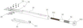
FIG. 1 illustrates an exploded view of a lamina distractor device provided in accordance with an embodiment of the present invention;
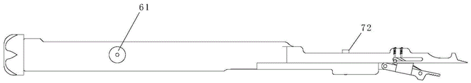
FIG. 2 illustrates a schematic structural view of a lamina distractor device provided according to an embodiment of the invention;
FIG. 3 illustrates a partial schematic structural view of a lamina distractor device provided in accordance with an embodiment of the present invention;
FIG. 4 illustrates a cross-sectional view of a lamina distractor device provided in accordance with an embodiment of the present invention;
FIG. 5 is a schematic structural view of another perspective of a lamina distractor device according to an embodiment of the invention;
FIG. 6 shows a schematic view of the distracting body of FIG. 1;
FIG. 7 shows a cross-sectional view of the distraction body of FIG. 1;
FIG. 8 is a schematic view of the distracting body of FIG. 1 from another perspective;
FIG. 9 shows a schematic structural view of the flipper of FIG. 1;
FIG. 10 shows a schematic view of the construction of the flipper of FIG. 1;
FIG. 11 shows a schematic view of the construction of the flipper of FIG. 1;
FIG. 12 shows a schematic structural view of the connector of FIG. 1;
FIG. 13 shows a schematic structural view of the connector of FIG. 1;
FIG. 14 shows a schematic structural view of the connector of FIG. 1;
figure 15 shows a schematic structural view of the drive member of figure 1;
fig. 16 shows a schematic view of the drive element of fig. 1.
Wherein the figures include the following reference numerals:
10. opening the main body; 11. a first spreader portion; 12. a chute; 13. mounting holes; 14. a first stop boss; 20. a moving assembly; 21. a connecting member; 22. a turnover piece; 221. a second distracting portion; 222. a second stop boss; 23. a pin shaft; 30. a drive section; 31. a transmission member; 311. an internal thread; 32. a drive member; 321. an external thread; 322. an operation end; 40. a first limit structure; 50. an angle indicator; 51. an angle indicating plate; 60. a second limit structure; 61. a limiting member; 62. a limiting groove; 70. a guide structure; 71. a guide groove; 72. and a guide post.
Detailed Description
The technical solutions in the embodiments of the present invention will be clearly and completely described below with reference to the drawings in the embodiments of the present invention, and it is obvious that the described embodiments are only a part of the embodiments of the present invention, and not all of the embodiments. The following description of at least one exemplary embodiment is merely illustrative in nature and is in no way intended to limit the invention, its application, or uses. All other embodiments, which can be derived by a person skilled in the art from the embodiments given herein without making any creative effort, shall fall within the protection scope of the present invention.
As shown in fig. 1 to 16, an embodiment of the present invention provides a vertebral plate distracting device, which includes a distracting main body 10, a moving assembly 20 and a driving part 30, wherein the distracting main body 10 has a first distracting part 11, the turning part 22 has a second distracting part 221 corresponding to the first distracting part 11, and a gap of the vertebral plate can be distracted by the cooperation of the first distracting part 11 and the second distracting part 221. In this embodiment, the moving assembly 20 includes a connecting member 21 and an overturning member 22, a first end of the connecting member 21 is adjustably disposed on the distracting main body 10, and the overturning member 22 is hinged to a second end of the connecting member 21, so as to drivingly connect the driving portion 30 and the overturning member 22, so as to drive the overturning member 22 to move and overturn relative to the distracting main body 10.
With the vertebral plate distraction device provided by the embodiment, when the vertebral plate needs to be distracted, the first distraction portion 11 and the second distraction portion 221 are firstly inserted into the gap, and then the driving portion 30 is used to drive the turnover part 22 to move relative to the distraction main body 10 so as to adjust the first end of the connecting part 21 to a proper position, in the process, the posterior movement of the spinous process is realized. After the first end of the connecting member 21 is adjusted to a proper position, the first end of the connecting member 21 is fixed, the driving portion 30 is continuously utilized to drive the turning member 22 to move relative to the distraction main body 10, and because the turning member 22 is hinged to the second end of the connecting member 21, the turning member 22 can turn relative to the distraction main body 10 under the action of the driving portion 30, so as to realize the distraction of the gap. By adopting the structure, the spinous process can move backwards while the gap is opened, and the use requirement is met.
In the present embodiment, the movement refers to a movement in the axial direction of the distraction body 10.
In this embodiment, the first spreading portion 11 is located at the front end of the spreading main body 10, the second spreading portion 221 is located at the front end of the turning member 22, the driving portion 30 is drivingly connected to the rear end of the turning member 22, and the hinge point between the second end of the connecting member 21 and the turning member 22 is located between the front end of the turning member 22 and the rear end of the turning member 22.
As shown in fig. 3 and 12 to 14, in this embodiment, the moving assembly 20 further includes a pin 23, the side wall of the expanding main body 10 is provided with a sliding groove 12, the sliding groove 12 extends along the axial direction of the expanding main body 10, and the pin 23 is inserted into the first end of the connecting member 21 and the sliding groove 12. The first end of the connecting member 21 can be connected to the distracting body 10 by the pin 23, and the first end of the connecting member 21 can slide in the sliding slot 12 by the pin 23 to adjust the position of the first end of the connecting member 21 on the distracting body 10. In the present embodiment, the pin 23 and the connecting member 21 are of an integral structure.
After moving the first end of the connecting member 21 to a proper position, the first end of the connecting member 21 needs to be fixed. In this embodiment, the vertebral plate distraction device further comprises a first limit structure 40, and the first limit structure 40 is disposed between the first end of the connecting member 21 and the distraction body 10 to limit the position of the first end of the connecting member 21 on the distraction body 10. The first limiting structure 40 includes, but is not limited to, a pin, a fastener, a marble, etc., as long as the first limiting structure 40 can limit the first end of the connecting member 21.
The first limit structure 40 may be directly disposed between the first end of the connecting member 21 and the distraction body 10, or the first limit structure 40 may be disposed between the pin 23 and the distraction body 10, so that the first limit structure 40 is indirectly disposed between the first end of the connecting member 21 and the distraction body 10.
In this embodiment, the first limiting structure 40 is disposed between the pin 23 and the distracting body 10, and the first limiting structure 40 limits the pin 23 from moving relative to the distracting body 10, and further limits the position of the first end of the connecting member 21 relative to the distracting body 10.
In order to improve the use diversity of the vertebral plate distraction device, the vertebral plate distraction device comprises at least two first limit structures 40, and the at least two first limit structures 40 are arranged at intervals along the axial direction of the distraction main body 10. When the first end of the connecting piece 21 is limited, one of the first limiting structures 40 is selected to limit the first end of the connecting piece 21 according to the use requirement, and the size of the retroversion of the spinous process can be switched.
In this embodiment, the lamina distraction device includes two first stop structures 40, the two first stop structures 40 limiting the size of the posterior shift of the spinous process to 6mm and 8mm, respectively.
As shown in fig. 3, 9-11, in this embodiment, the lamina distractor device further includes an angle indicator 50, the angle indicator 50 being disposed on the flipper 22. The angle indicator 50 can be used to indicate the angle at which the everter 22 is opened relative to the distracting body 10. In other embodiments, the angle indicator 50 can be provided on the distraction body 10, or both the distraction body 10 and the flipper 22 can be provided with the angle indicator 50.
Specifically, the angle indicator 50 includes an angle indicating plate 51, the angle indicating plate 51 is disposed on the flip 22, and an upper surface of the angle indicating plate 51 is an inclined surface. When the turning member 22 is turned to a predetermined angle relative to the spreading main body 10, the upper surface of the angle indicating plate 51 is parallel to the lower surface of the spreading main body 10, so as to prompt the user that the turning member 22 is turned to the right position.
The angle indicator 50 may also be a component with an angle scale provided on the distracting body 10 and/or the flipper 22.
As shown in fig. 1 and 3, the driving portion 30 includes a transmission member 31, the transmission member 31 is movably disposed on the expanding body 10, and a first end of the transmission member 31 is hinged to an end of the turning member 22 away from the second expanding portion 221. The transmission member 31 can drive the turning member 22 to move and rotate relative to the main spreading body 10.
In the present embodiment, the upper surface of the transmission member 31 is attached to the lower surface of the distraction body 10, and the transmission member 31 can translate along the axial direction of the distraction body 10.
As shown in fig. 1, 15 and 16, the driving portion 30 further includes a driving member 32, the driving member 32 is movable and rotatable relative to the distracting body 10, an axis of the driving member 32 is coincident with or parallel to an axis of the transmission member 31, and the driving member 32 is threadedly engaged with the second end of the transmission member 31. When the driving member 32 moves relative to the spreading body 10, the driving member 32 drives the transmission member 31 to move. When the driving member 32 rotates relative to the distracting body 10, the driving member 32 can drive the transmission member 31 to translate relative to the distracting body 10 through the threaded structure.
Specifically, the distraction body 10 has a mounting hole 13, a first end of the driving element 32 is rotatably disposed in the mounting hole 13, a first end of the driving element 32 is provided with an external thread 321, a second end of the transmission element 31 is provided with an internal thread 311, and the second end of the driving element 32 is located outside the mounting hole 13 to form an operation end 322. A sleeve is arranged at the second end of the transmission member 31, the sleeve is provided with an internal thread 311, and the first end of the driving member 32 is arranged in the sleeve in a penetrating way. By rotating or pushing the operating end 322, the driving member 32 can be rotated or pushed and pulled to facilitate the operation.
As shown in fig. 2, the lamina distractor device further includes a second stop 60, the second stop 60 being disposed between the distracting body 10 and the driving member 32 to limit movement of the driving member 32 relative to the distracting body 10. After the first end of the connecting member 21 is moved to a proper position by the driving member 32 and the transmission member 31, the second limiting structure 60 is used to limit the driving member 32 from moving relative to the distracting body 10, and the first limiting structure 40 is used to limit the position of the first end of the connecting member 21 on the distracting body 10, and then the driving member 32 is rotated, because the driving member 32 is in threaded connection with the transmission member 31, the transmission member 31 will translate relative to the driving member 32 and drive the turning member 22 to turn relative to the distracting body 10 until the second distracting portion 221 on the turning member 22 is opened by a preset angle relative to the first distracting portion 11 on the distracting body 10.
In the present embodiment, the second limiting structure 60 includes a limiting member 61 and a plurality of limiting grooves 62, the plurality of limiting grooves 62 are disposed on the sidewall of the driving member 32 at intervals, the limiting grooves 62 extend along the circumferential direction of the driving member 32, and the limiting member 61 is movably disposed on the spreading main body 10 and disposed corresponding to the limiting grooves 62. When the limiting member 61 is located outside the limiting groove 62, the driving member 32 can move and rotate relative to the distraction body 10, and when the limiting member 61 is inserted into the limiting groove 62, the driving member 32 can rotate relative to the distraction body 10.
As shown in fig. 1, the lamina distractor further includes a guide structure 70, the guide structure 70 being disposed between the transmission member 31 and the distracting body 10. The driver 31 can be guided by the guide structure 70 when the driver 31 moves relative to the distracting body 10.
The guide structure 70 includes a guide groove 71 and a guide post 72, the guide groove 71 is disposed on one of the transmission member 31 and the distracting body 10, the guide groove 71 extends along the axial direction of the distracting body 10, the guide post 72 is disposed on the other of the transmission member 31 and the distracting body 10, and the guide post 72 movably penetrates through the guide groove 71.
When the driving member 32 rotates relative to the driving member 31, the driving member 31 can be restricted from rotating relative to the distracting body 10 by the cooperation of the guide groove 71 and the guide post 72, so as to ensure that the driving member 31 can move horizontally relative to the distracting body 10.
In order to limit the depth of the vertebral plate distraction device inserted into the vertebral plate gap, a first stop boss 14 is arranged on the distraction main body 10, a second stop boss 222 is arranged on the turnover part 22, the first stop boss 14 is positioned behind the first distraction part 11, and the second stop boss 222 is positioned behind the second distraction part 221.
In order to ensure the contact firmness of the vertebral plate distraction device and the skeleton, anti-slip structures are arranged on the first distraction part 11 and the second distraction part 221. In this embodiment, the anti-slip structure is a plurality of tooth-shaped bosses.
In this embodiment, the front end of the distraction main body 10 includes two support arms parallel to each other, the first distraction portion 11 is disposed on each of the two support arms, the vertebral plate distraction device includes two moving components 20, and the two moving components 20 are disposed on the two support arms respectively, so that the stability can be ensured.
In this embodiment, the lamina distractor device is used in an internal spinal fixation procedure.
To facilitate understanding of the lamina distractor device provided in this embodiment, the following is explained in conjunction with the operational steps:
(1) screwing the lock pin (the limiting piece 61) out of the lock groove (the limiting groove 62);
(2) the driving element 32 is pulled outwards until the pin shaft 23 moves to the position of a top bead (a first limiting structure) at 6mm or 8mm, and the position of the pin shaft 23 can be determined by using the top bead;
(3) when the position of the pin shaft 23 is determined, the rotating lock pin enters the lock groove, the driving part 32 can only rotate at the moment, and the driving part 32 is rotated, and at the moment, the overturning part 22 overturns until the opening angle of the upper surface of the angle indicating plate 51 reaches the specified angle.
Through the device that this embodiment provided, can reach the effect that promotes (6mm, 8mm) vertebral plate when realizing that the vertebral plate struts predetermined width, and then satisfy the user demand.
It is noted that the terminology used herein is for the purpose of describing particular embodiments only and is not intended to be limiting of example embodiments according to the present application. As used herein, the singular forms "a", "an" and "the" are intended to include the plural forms as well, and it should be understood that when the terms "comprises" and/or "comprising" are used in this specification, they specify the presence of stated features, steps, operations, devices, components, and/or combinations thereof, unless the context clearly indicates otherwise.
The relative arrangement of the components and steps, the numerical expressions and numerical values set forth in these embodiments do not limit the scope of the present invention unless specifically stated otherwise. Meanwhile, it should be understood that the sizes of the respective portions shown in the drawings are not drawn in an actual proportional relationship for the convenience of description. Techniques, methods, and apparatus known to those of ordinary skill in the relevant art may not be discussed in detail but are intended to be part of the specification where appropriate. In all examples shown and discussed herein, any particular value should be construed as merely illustrative, and not limiting. Thus, other examples of the exemplary embodiments may have different values. It should be noted that: like reference numbers and letters refer to like items in the following figures, and thus, once an item is defined in one figure, further discussion thereof is not required in subsequent figures.
In the description of the present invention, it is to be understood that the orientation or positional relationship indicated by the orientation words such as "front, rear, upper, lower, left, right", "lateral, vertical, horizontal" and "top, bottom", etc. are usually based on the orientation or positional relationship shown in the drawings, and are only for convenience of description and simplicity of description, and in the case of not making a reverse description, these orientation words do not indicate and imply that the device or element being referred to must have a specific orientation or be constructed and operated in a specific orientation, and therefore, should not be considered as limiting the scope of the present invention; the terms "inner and outer" refer to the inner and outer relative to the profile of the respective component itself.
Spatially relative terms, such as "above … …," "above … …," "above … …," "above," and the like, may be used herein for ease of description to describe one device or feature's spatial relationship to another device or feature as illustrated in the figures. It will be understood that the spatially relative terms are intended to encompass different orientations of the device in use or operation in addition to the orientation depicted in the figures. For example, if a device in the figures is turned over, devices described as "above" or "on" other devices or configurations would then be oriented "below" or "under" the other devices or configurations. Thus, the exemplary term "above … …" can include both an orientation of "above … …" and "below … …". The device may be otherwise variously oriented (rotated 90 degrees or at other orientations) and the spatially relative descriptors used herein interpreted accordingly.
It should be noted that the terms "first", "second", and the like are used to define the components, and are only used for convenience of distinguishing the corresponding components, and the terms have no special meanings unless otherwise stated, and therefore, the scope of the present invention should not be construed as being limited.
The above description is only a preferred embodiment of the present invention and is not intended to limit the present invention, and various modifications and changes may be made by those skilled in the art. Any modification, equivalent replacement, or improvement made within the spirit and principle of the present invention should be included in the protection scope of the present invention.
Claims (13)
1. A lamina distraction device, comprising:
a spreading body (10) having a first spreading section (11);
the moving assembly (20) comprises a connecting piece (21) and a turnover piece (22), a first end of the connecting piece (21) is arranged on the spreading main body (10) in a position-adjustable mode, the turnover piece (22) is hinged to a second end of the connecting piece (21), and the turnover piece (22) is provided with a second spreading portion (221) arranged corresponding to the first spreading portion (11);
the driving part (30) is in driving connection with the overturning part (22) so as to drive the overturning part (22) to move and overturn relative to the spreading main body (10).
2. The vertebral plate spacer device according to claim 1, characterized in that the moving assembly (20) further comprises a pin (23), a sliding slot (12) is provided on the side wall of the spacer body (10), the sliding slot (12) extends along the axial direction of the spacer body (10), and the pin (23) is inserted into the first end of the connecting member (21) and the sliding slot (12).
3. The lamina distraction device of claim 1, further comprising a first stop structure (40), the first stop structure (40) being disposed between the first end of the connector (21) and the distraction body (10) to limit the position of the first end of the connector (21) on the distraction body (10).
4. The lamina distraction device of claim 3, comprising at least two of the first stop structures (40), the at least two first stop structures (40) being spaced apart in an axial direction of the distraction body (10).
5. The lamina distractor device of claim 1, further comprising an angle indicator (50), the angle indicator (50) being disposed on the distracting body (10) and/or the flipper (22).
6. The lamina distractor device of claim 5, wherein the angle indicator (50) includes an angle indicator plate (51), the angle indicator plate (51) being disposed on the flipper (22), an upper surface of the angle indicator plate (51) being beveled.
7. The lamina distractor device of any one of claims 1 to 6, wherein the drive part (30) comprises a transmission member (31), the transmission member (31) being movably arranged on the distracting body (10), a first end of the transmission member (31) being articulated with an end of the flipper (22) remote from the second distracting part (221).
8. The lamina distractor device of claim 7, wherein the drive portion (30) further comprises a drive member (32), the drive member (32) being movable and rotatable relative to the distracting body (10), the drive member (32) having an axis coincident with or parallel to the axis of the drive member (31), the drive member (32) being threadably engaged with the second end of the drive member (31).
9. The lamina distractor device of claim 8, wherein the distracting body (10) has a mounting hole (13), the driving member (32) is rotatably disposed through the mounting hole (13) at a first end thereof, the driving member (32) is provided with external threads (321) at a first end thereof, the transmission member (31) is provided with internal threads (311) at a second end thereof, and the driving member (32) is located outside the mounting hole (13) at a second end thereof to form an operating end (322).
10. The lamina distraction device of claim 8, further comprising a second stop structure (60), the second stop structure (60) being disposed between the distraction body (10) and the drive member (32) to limit movement of the drive member (32) relative to the distraction body (10).
11. The lamina distractor device of claim 10, wherein the second limiting structure (60) includes a limiting member (61) and a plurality of limiting grooves (62), the plurality of limiting grooves (62) are disposed at intervals on the sidewall of the driving member (32), the limiting grooves (62) extend along the circumferential direction of the driving member (32), and the limiting member (61) is movably disposed through the distracting body (10) and corresponding to the limiting grooves (62).
12. The lamina distractor device of claim 7, further comprising a guide structure (70), the guide structure (70) being disposed between the driver (31) and the distracting body (10).
13. The lamina distraction device of any one of claims 1-6,
a first stopping boss (14) is arranged on the expanding main body (10), and the first stopping boss (14) is positioned behind the first expanding part (11); and/or the presence of a gas in the gas,
the turnover piece (22) is provided with a second stop boss (222), and the second stop boss (222) is located behind the second spreading portion (221).
Priority Applications (1)
| Application Number | Priority Date | Filing Date | Title |
|---|---|---|---|
| CN202011602810.6A CN112587221B (en) | 2020-12-29 | 2020-12-29 | Vertebral plate distraction device |
Applications Claiming Priority (1)
| Application Number | Priority Date | Filing Date | Title |
|---|---|---|---|
| CN202011602810.6A CN112587221B (en) | 2020-12-29 | 2020-12-29 | Vertebral plate distraction device |
Publications (2)
| Publication Number | Publication Date |
|---|---|
| CN112587221A true CN112587221A (en) | 2021-04-02 |
| CN112587221B CN112587221B (en) | 2022-04-19 |
Family
ID=75203935
Family Applications (1)
| Application Number | Title | Priority Date | Filing Date |
|---|---|---|---|
| CN202011602810.6A Active CN112587221B (en) | 2020-12-29 | 2020-12-29 | Vertebral plate distraction device |
Country Status (1)
| Country | Link |
|---|---|
| CN (1) | CN112587221B (en) |
Citations (6)
| Publication number | Priority date | Publication date | Assignee | Title |
|---|---|---|---|---|
| CN107684444A (en) * | 2017-09-19 | 2018-02-13 | 江苏艾迪尔医疗科技股份有限公司 | Vertebrae strutting device |
| CN210204855U (en) * | 2019-04-23 | 2020-03-31 | 孙宇 | Vertebral lamina opening forceps |
| CN111134901A (en) * | 2020-02-27 | 2020-05-12 | 孟会琴 | Traceless implanting device for nasal bone prosthesis and using method of traceless implanting device |
| CN111449746A (en) * | 2020-05-26 | 2020-07-28 | 郴州市第一人民医院 | Active intervertebral body opening reduction forceps |
| CN211674375U (en) * | 2019-12-19 | 2020-10-16 | 温州医科大学附属第二医院、温州医科大学附属育英儿童医院 | High-position tibia osteotomy distractor |
| CN211934156U (en) * | 2020-03-05 | 2020-11-17 | 北京积水潭医院 | Intervertebral space struts ware |
-
2020
- 2020-12-29 CN CN202011602810.6A patent/CN112587221B/en active Active
Patent Citations (6)
| Publication number | Priority date | Publication date | Assignee | Title |
|---|---|---|---|---|
| CN107684444A (en) * | 2017-09-19 | 2018-02-13 | 江苏艾迪尔医疗科技股份有限公司 | Vertebrae strutting device |
| CN210204855U (en) * | 2019-04-23 | 2020-03-31 | 孙宇 | Vertebral lamina opening forceps |
| CN211674375U (en) * | 2019-12-19 | 2020-10-16 | 温州医科大学附属第二医院、温州医科大学附属育英儿童医院 | High-position tibia osteotomy distractor |
| CN111134901A (en) * | 2020-02-27 | 2020-05-12 | 孟会琴 | Traceless implanting device for nasal bone prosthesis and using method of traceless implanting device |
| CN211934156U (en) * | 2020-03-05 | 2020-11-17 | 北京积水潭医院 | Intervertebral space struts ware |
| CN111449746A (en) * | 2020-05-26 | 2020-07-28 | 郴州市第一人民医院 | Active intervertebral body opening reduction forceps |
Also Published As
| Publication number | Publication date |
|---|---|
| CN112587221B (en) | 2022-04-19 |
Similar Documents
| Publication | Publication Date | Title |
|---|---|---|
| EP2328490B1 (en) | Conical interspinous apparatus | |
| EP1807012B1 (en) | Nterspinous distraction devices | |
| US8747440B2 (en) | Conical interspinous apparatus and a method of performing interspinous distraction | |
| US8409087B2 (en) | Expandable retractor and methods incorporating the same | |
| KR102201120B1 (en) | Surgical access system | |
| US20070083210A1 (en) | Apparatus and method for minimally invasive spine surgery | |
| US20090264930A1 (en) | Minimally invasive Systems and Methods for Insertion of a Connecting Member Adjacent the Spinal Column | |
| WO2013052807A2 (en) | Bone fusion system | |
| US10660631B1 (en) | Pedicle screw mounted retractor system | |
| US8728127B2 (en) | Bone plate incorporating a compression mechanism and associated surgical methods | |
| CN112587221B (en) | Vertebral plate distraction device | |
| CN115444529A (en) | Combined supporting device for expanding and forming vertebral canal | |
| CN112568986B (en) | Vertebral plate distraction and prosthesis implantation device | |
| US20230157733A1 (en) | Endoscopic interspinous insert | |
| CN103445854B (en) | Locator for vertebral arch pedicle screw implanting operation | |
| CN218979026U (en) | Channel fixing device capable of being opened | |
| CN215018795U (en) | Spinal canal enlarging device | |
| CN219461548U (en) | Laminoplasty prosthesis | |
| CN106473783B (en) | Distraction piece for pedicle of vertebral arch fixing system | |
| CN112451072A (en) | Clavicle fracture closed reduction device and method |
Legal Events
| Date | Code | Title | Description |
|---|---|---|---|
| PB01 | Publication | ||
| PB01 | Publication | ||
| SE01 | Entry into force of request for substantive examination | ||
| SE01 | Entry into force of request for substantive examination | ||
| GR01 | Patent grant | ||
| GR01 | Patent grant |