CN112584046B - Image pickup apparatus, lens unit, image pickup system, and control method thereof - Google Patents
Image pickup apparatus, lens unit, image pickup system, and control method thereof Download PDFInfo
- Publication number
- CN112584046B CN112584046B CN202011432079.7A CN202011432079A CN112584046B CN 112584046 B CN112584046 B CN 112584046B CN 202011432079 A CN202011432079 A CN 202011432079A CN 112584046 B CN112584046 B CN 112584046B
- Authority
- CN
- China
- Prior art keywords
- communication
- unit
- correction
- image pickup
- timing
- Prior art date
- Legal status (The legal status is an assumption and is not a legal conclusion. Google has not performed a legal analysis and makes no representation as to the accuracy of the status listed.)
- Active
Links
Images


Classifications
-
- H—ELECTRICITY
- H04—ELECTRIC COMMUNICATION TECHNIQUE
- H04N—PICTORIAL COMMUNICATION, e.g. TELEVISION
- H04N23/00—Cameras or camera modules comprising electronic image sensors; Control thereof
- H04N23/60—Control of cameras or camera modules
- H04N23/665—Control of cameras or camera modules involving internal camera communication with the image sensor, e.g. synchronising or multiplexing SSIS control signals
-
- H—ELECTRICITY
- H04—ELECTRIC COMMUNICATION TECHNIQUE
- H04N—PICTORIAL COMMUNICATION, e.g. TELEVISION
- H04N23/00—Cameras or camera modules comprising electronic image sensors; Control thereof
- H04N23/50—Constructional details
- H04N23/55—Optical parts specially adapted for electronic image sensors; Mounting thereof
-
- H—ELECTRICITY
- H04—ELECTRIC COMMUNICATION TECHNIQUE
- H04N—PICTORIAL COMMUNICATION, e.g. TELEVISION
- H04N23/00—Cameras or camera modules comprising electronic image sensors; Control thereof
- H04N23/60—Control of cameras or camera modules
- H04N23/68—Control of cameras or camera modules for stable pick-up of the scene, e.g. compensating for camera body vibrations
- H04N23/682—Vibration or motion blur correction
- H04N23/685—Vibration or motion blur correction performed by mechanical compensation
- H04N23/687—Vibration or motion blur correction performed by mechanical compensation by shifting the lens or sensor position
-
- H—ELECTRICITY
- H04—ELECTRIC COMMUNICATION TECHNIQUE
- H04N—PICTORIAL COMMUNICATION, e.g. TELEVISION
- H04N23/00—Cameras or camera modules comprising electronic image sensors; Control thereof
- H04N23/60—Control of cameras or camera modules
- H04N23/66—Remote control of cameras or camera parts, e.g. by remote control devices
- H04N23/663—Remote control of cameras or camera parts, e.g. by remote control devices for controlling interchangeable camera parts based on electronic image sensor signals
-
- H—ELECTRICITY
- H04—ELECTRIC COMMUNICATION TECHNIQUE
- H04N—PICTORIAL COMMUNICATION, e.g. TELEVISION
- H04N23/00—Cameras or camera modules comprising electronic image sensors; Control thereof
- H04N23/60—Control of cameras or camera modules
- H04N23/667—Camera operation mode switching, e.g. between still and video, sport and normal or high- and low-resolution modes
-
- H—ELECTRICITY
- H04—ELECTRIC COMMUNICATION TECHNIQUE
- H04N—PICTORIAL COMMUNICATION, e.g. TELEVISION
- H04N23/00—Cameras or camera modules comprising electronic image sensors; Control thereof
- H04N23/60—Control of cameras or camera modules
- H04N23/68—Control of cameras or camera modules for stable pick-up of the scene, e.g. compensating for camera body vibrations
- H04N23/681—Motion detection
- H04N23/6812—Motion detection based on additional sensors, e.g. acceleration sensors
-
- H—ELECTRICITY
- H04—ELECTRIC COMMUNICATION TECHNIQUE
- H04N—PICTORIAL COMMUNICATION, e.g. TELEVISION
- H04N23/00—Cameras or camera modules comprising electronic image sensors; Control thereof
- H04N23/60—Control of cameras or camera modules
- H04N23/68—Control of cameras or camera modules for stable pick-up of the scene, e.g. compensating for camera body vibrations
- H04N23/682—Vibration or motion blur correction
- H04N23/684—Vibration or motion blur correction performed by controlling the image sensor readout, e.g. by controlling the integration time
-
- H—ELECTRICITY
- H04—ELECTRIC COMMUNICATION TECHNIQUE
- H04N—PICTORIAL COMMUNICATION, e.g. TELEVISION
- H04N23/00—Cameras or camera modules comprising electronic image sensors; Control thereof
- H04N23/70—Circuitry for compensating brightness variation in the scene
- H04N23/749—Circuitry for compensating brightness variation in the scene by influencing the pick-up tube voltages
Abstract
The invention provides an image pickup apparatus, a lens unit, an image pickup system, and a control method thereof. The imaging system includes a camera body and a lens unit mountable to the camera body. The lens unit detects shake by a shake detection unit. Drive control of the image shake correction unit is performed in accordance with an image shake correction amount calculated based on shake. The camera body sets a timing of obtaining the shake detected by the shake detection unit based on information transmitted to the lens unit. In the first communication, the camera communication control unit transmits information on the base point to the lens communication control unit, and in the second communication, the camera communication control unit transmits information on a relative time with respect to the base point transmitted in the first communication to the lens communication control unit.
Description
(this application is a divisional application of an application having an application date of 24.2.2017 and an application number of 2017101118466 and an invention name of "image pickup apparatus, lens unit, image pickup system, and control method thereof.)
Technical Field
The invention relates to an image pickup apparatus, a lens unit, an image pickup system, and a control method of the image pickup system.
Background
There is a technique of detecting hand shake or the like applied to an image pickup apparatus and correcting image shake caused by the shake. Image shake correction, which is a method of moving an image shake correction lens in accordance with detected shake, is called "optical image shake correction" or "optical anti-shake". In addition, image shake correction that corrects shake of an image captured during capturing of a moving image by cutting out and outputting a part of the captured image according to the detected shake is referred to as "electronic image shake correction" or "electronic anti-shake". In recent years, a technique is known that enhances the image shake correction effect against large image shake due to walking shooting or the like by widening the image shake correction range particularly on the Wide-angle side (Wide side) during shooting of a moving image. Using both the optical image shake correction and the electronic image shake correction enables a greater correction effect to be obtained and also enables larger image shake to be coped with.
On the other hand, in the interchangeable lens camera system, a structure is conceived in which: a lens unit attached to a camera body includes an optical image shake correction mechanism, and the camera body includes an optical image shake correction unit or an electronic image shake correction unit. That is, it is a system that combines the lens unit and the camera body so that shake correction is performed independently of each other. In such a system, a technique is disclosed: the lens unit and the camera body cooperatively control shake correction by communicating with each other, rather than independently controlling shake correction, thereby enhancing the correction effect. Japanese patent laid-open No. 2014-39131 discloses a technique of: the camera body transmits exposure time (shutter speed) information to the lens unit, and determines the detection timing of the image shake correction means a plurality of times based on the shutter speed information. In addition, japanese patent laid-open No. 2015-161730 discloses a technique of: the amount of movement of the object image on the imaging surface matches the output timing from the shake detection section, and therefore the detection accuracy of the angular velocity of the object is enhanced.
In order for the lens unit and the camera body to cooperatively perform image shake correction by communicating with each other, the camera body needs to transmit the exposure center timing of image capturing to the lens unit. In addition, such a case where the camera body attempts to transmit the exposure center timing to the lens unit which communicates once may cause a change in communication time due to an overlap with another communication, and as a result, accurate exposure center timing may not be transmitted.
Although japanese patent laid-open No. 2014-39131 discloses that shutter speed information is transmitted simultaneously with vertical synchronization timing, details thereof are not disclosed, and communication deviation is not involved. In addition, japanese patent laid-open No. 2015-161730 discloses setting the timing for obtaining data by using information on the exposure time and frame rate, but does not disclose details thereof, and does not relate to communication deviation.
Disclosure of Invention
The present invention performs image correction by avoiding communication timing deviation due to overlapping of communications in an image capturing system including a lens unit and a main body of an image capturing apparatus that communicate with each other.
The present invention is an image pickup apparatus for communicating with a lens unit including: a first communication unit; a first correction unit for correcting image shake in an image due to shake; and a first control unit configured to obtain a shake detection signal and control the first correction unit, wherein the image pickup apparatus includes: an image pickup unit; a second communication unit for communicating with the lens unit; and a setting unit configured to set a timing at which the first control unit obtains the shake detection signal based on information transmitted to the lens unit, wherein in a first communication, the second communication unit transmits information relating to a base point serving as information for the setting unit to set the timing to the first communication unit, and in a second communication, the second communication unit transmits information relating to a relative time with respect to the base point to the first communication unit.
The present invention is a lens unit including: a first communication unit for communicating with a main body of the image pickup apparatus; a first correction unit for correcting an image shake in an image due to a shake; and a control unit configured to obtain a shake detection signal and control the first correction unit, wherein in first communication, the first communication unit receives information on a base point transmitted as information of a setting unit setting timing of the main body from a second communication unit included in the main body, in second communication, the first communication unit receives information on a relative time with respect to the base point from the second communication unit included in the main body, and the control unit obtains the shake detection signal at a timing determined by the base point and the relative time.
The present invention is an image pickup system including a main body of an image pickup apparatus and a lens unit including: a first communication unit for communicating with the main body; a correction unit for correcting image shake in an image due to shake; and a control unit for obtaining a shake detection signal and controlling the correction unit, the main body including: an image pickup unit; a second communication unit for communicating with the lens unit; and a setting unit configured to set a timing at which the control unit obtains the shake detection signal based on information transmitted to the lens unit, wherein in a first communication, the second communication unit transmits information relating to a base point serving as information at which the setting unit sets the timing to the first communication unit, and in a second communication, the second communication unit transmits information relating to a relative time with respect to the base point to the first communication unit.
The present invention is a control method executed in an image pickup system including an image pickup apparatus main body and a lens unit including: a first communication unit configured to communicate with the image pickup apparatus main body; a correction unit for correcting image shake in an image due to shake; and a control unit configured to obtain a shake detection signal and control the correction unit, the image pickup apparatus main body including: an image pickup unit; a second communication unit for communicating with the lens unit; and a setting unit configured to set a timing at which the shake detection signal is obtained by the control unit based on information transmitted to the lens unit, the control method of the image pickup system including: in the first communication, the second communication unit transmits information relating to a base point serving as information for the setting unit to set the timing to the first communication unit; and in a second communication, the second communication unit transmits information about a relative time with respect to the base point to the first communication unit.
Other features of the present invention will become apparent from the following description of exemplary embodiments with reference to the attached drawings.
Drawings
Fig. 1 is a block diagram showing a configuration example of an image pickup system according to an embodiment of the present invention.
Fig. 2 is a block diagram of a portion related to control of image shake correction.
Fig. 3 is a block diagram showing details of the electronic image shake correction control unit.
Fig. 4 shows the communication and its timing in the first embodiment.
Fig. 5 is a flowchart showing communication and control of the camera body in the first embodiment.
Fig. 6 is a flowchart showing communication and control of the lens unit in the first embodiment.
Fig. 7 is a flowchart showing communication and control of the camera body in the second embodiment.
Fig. 8 is a flowchart showing communication and control of the camera body in the third embodiment.
Fig. 9 is a flowchart showing communication and control of the lens unit in the third embodiment.
Fig. 10 shows communication and its timing in the fourth embodiment.
Fig. 11 is a flowchart showing communication and control of the camera body in the fourth embodiment.
Fig. 12 is a flowchart showing communication and control of the lens unit in the fourth embodiment.
Fig. 13 is a diagram showing the relationship between the focal length and the image shake correction movable range.
Fig. 14 is a diagram showing a relationship between a focal length and a division coefficient.
Fig. 15 is a conceptual diagram of rolling shutter distortion correction.
Fig. 16 is a schematic diagram of a pitch (pitch) direction, a yaw (yaw) direction, and a roll (roll) direction in the image pickup apparatus.
Detailed Description
Hereinafter, various embodiments of the present invention will be described in detail with reference to the accompanying drawings. First, a description will be given of matters common to the respective embodiments. Fig. 1 is a block diagram showing the structure of an image pickup system according to an embodiment of the present invention. The imaging system is an interchangeable lens digital camera mainly used for performing shooting of still images and moving images. The application range of the present invention is not limited to the digital camera, and the present invention can be applied to various image pickup systems.
The image pickup system shown in fig. 1 includes a lens unit and a camera body, and the lens unit is used by being mounted on the camera body. The zoom unit 101 of the lens unit includes a zoom lens of varying magnification. The zoom drive control unit 102 drives and controls the zoom unit 101. The diaphragm unit 103 has a diaphragm function. The diaphragm drive control unit 104 drives and controls the diaphragm unit 103. The image shake correction unit 105 includes an image shake correction lens (hereinafter, also referred to as "correction lens") such as a shift lens. The image shake correction unit 105 is a first image shake correction unit, and the optical image shake correction control unit 106 performs drive control. The focus unit 107 includes a focus lens that forms an object image by performing focus adjustment. The focus drive control unit 108 drives and controls the focus unit 107.
The lens operation unit 109 is an operation unit for a user to operate the lens unit. The lens shake detection unit 110 detects the amount of shake applied to the lens unit, and outputs a detection signal to the lens system control unit 111. A lens system control unit (hereinafter referred to as "lens control unit") 111 controls the entire lens unit, and includes a CPU (central processing unit), and generally controls each of a drive control unit and a correction control unit of the lens unit. The lens system control unit 111 communicates with the control unit of the camera body via the lens communication control unit 112.
Next, a description will be given of the camera body. The camera body includes a shutter unit 113. The shutter drive control unit 114 drives and controls the shutter unit 113. The image pickup unit 115 includes an image pickup element, photoelectrically converts an optical image formed by each lens group, and outputs an electric signal. The image pickup signal processing unit 116 converts the electric signal output from the image pickup unit 115 into a video image signal. The video image signal processing unit 117 processes the video image signal output from the image pickup signal processing unit 116 according to the purpose. For example, the video image signal processing unit 117 changes the cut-out position of the video image signal in accordance with the correction amount by the electronic image shake correction control unit 123. The electronic image shake correction control unit 123 is a second image shake correction unit, and performs control of image shake correction by cutout of an image. Note that the second image shake correction is not limited to the electronic image shake correction, and it includes, for example, an image shake correction by drive control of the image pickup element and an image shake correction by drive control of the movable optical element within the camera body.
The display unit 118 displays an image as necessary based on the signal output from the video image signal processing unit 117. The storage unit 119 stores various data such as video image information and the like. The power supply unit 120 supplies power to the entire system according to usage. The camera operation unit 121 is an operation unit for the user's operation of the camera system, and outputs an operation signal to the camera system control unit 124. The camera shake detection unit 122 detects the amount of shake applied to the camera, and outputs a detection signal to the camera system control unit 124. A camera system control unit (hereinafter referred to as "camera control unit") 124 has a CPU, and generally controls the entire camera system. The camera system control unit 124 communicates with the lens communication control unit 112 of the lens unit via the camera communication control unit 125. That is, in a state where the lens unit is mounted on and electrically connected to the camera body, mutual communication is performed by using the lens communication control unit 112 and the camera communication control unit 125.
Next, a description will be given of a schematic operation of the image pickup system having the above-described structure. The lens operation unit 109 and/or the camera operation unit 121 include an image shake correction switch that can select ON/OFF of image shake correction. If the user operates the image shake correction switch and selects image shake correction to be ON, the lens system control unit 111 or the camera system control unit 124 provides an instruction to the optical image shake correction control unit 106 or the electronic image shake correction control unit 123 to perform an image shake correction operation. Each image shake control unit controls image shake correction until an instruction to turn off the image shake correction is provided.
In addition, the camera operation unit 121 includes an image shake correction mode switch that can select the first mode or the second mode with respect to image shake correction. The first mode is a mode in which image shake correction is performed only by using optical image shake correction (first image shake correction). The second mode is a mode in which image shake correction is performed by using optical image shake correction and electronic image shake correction (second image shake correction). If the first mode is selected, the readout position of the image pickup unit 115 is fixed, and wider angle shooting is compatible by expanding the readout range by a certain amount. In addition, if the second mode is selected, the cut-out position is changed according to the image shake correction amount instead of narrowing the cut-out range of the video image signal by the video image signal processing unit 117, and as a result, it is possible to cope with a large image shake.
The camera operation unit 121 includes a shutter release button configured such that a first switch (SW 1) and a second switch (SW 2) are sequentially turned on according to the amount of pressing. The first switch SW1 is turned on if the user presses the shutter release button approximately half, and the second switch SW2 is turned on if the shutter release button is fully pressed. If SW1 is turned on, the focus drive control unit 108 drives the focus unit 107 and performs focus adjustment, and the diaphragm drive control unit 104 drives the diaphragm unit 103 and sets it to an appropriate exposure amount. If SW2 is on, image data obtained from the light image exposed to the image sensing unit 115 is stored in the storage unit 119.
In addition, the camera operation unit 121 includes a moving image recording switch. The camera starts shooting a moving image after pressing the moving image recording switch, and if the user presses the moving image recording switch again during recording, the recording ends. If the user operates the shutter release button during shooting of a moving image and SW1 and SW2 are turned on, processing of obtaining and recording a still image during recording of the moving image is performed. In addition, the camera operation unit 121 includes a reproduction mode selection switch that can select a reproduction mode. If the reproduction mode is selected by the operation of the reproduction mode selection switch, the camera stops the anti-shake (image shake correction) operation.
A description will be given of image shake correction control in the image capturing system with reference to fig. 2 and 16. Fig. 2 is a block diagram showing in more detail a portion related to image shake correction control in the entire image capturing system. Fig. 16 shows the pitch direction, yaw direction, and roll direction. The lens shake detection unit 110 and the camera shake detection unit 122 in fig. 2 detect angular velocity data by using a gyro sensor serving as a shake detection sensor, and output a detection voltage. The lens shake detection unit 110 has a pitch direction shake detection sensor and a yaw direction shake detection sensor. Further, the camera shake detection unit 122 has a roll direction shake detection sensor. As shown in fig. 16, in the image pickup apparatus, the optical axis of the image pickup optical system is defined as a Z axis, the vertical direction of the positive position is defined as a Y axis, and the direction orthogonal to the Y axis and the Z axis is defined as an X axis. Therefore, the pitch direction is a direction of rotation around the X axis (pitch direction), the yaw direction is a direction of rotation around the Y axis (yaw direction), and the roll direction is a direction of rotation around the Z axis (direction in which the image pickup plane rotates in a plane perpendicular to the optical axis). That is, the pitch direction is an inclination direction with respect to the horizontal plane in the vertical direction of the image pickup apparatus, and the yaw direction is an inclination direction with respect to the vertical plane in the horizontal direction of the image pickup system, and they are orthogonal to each other.
The pitch-direction shake detection sensor detects shake information proportional to a shake in the pitch direction. The yaw direction shake detection sensor detects shake information proportional to a shake in the yaw direction. The rolling direction shake detection sensor detects shake information proportional to a shake in a rotational direction in a plane perpendicular to the optical axis. Each shake information is obtained as angular velocity data. Note that in fig. 2, since the same structure is provided for the pitch direction and the yaw direction, only the structure of one axis will be described.
The lens shake detection unit 110 outputs angular velocity data obtained by an angular velocity sensor such as a gyro sensor, which is used as a detection voltage. The angular velocity detection AD conversion unit 201 converts the detection signal output from the lens shake detection unit 110 into digital data. The high-pass filter 202 removes an offset component and a temperature drift component of the angular velocity data, and outputs the result to the integrating unit 203. The integrating unit 203 integrates the angular velocity data by pseudo integration mainly using a low-pass filter, and converts the result into angle data. The sensitivity multiplying unit 204 for optical image shake correction converts the angle data obtained from the integrating unit 203 into a drive control amount (shift amount) of the image shake correction lens. This sensitivity changes every time the focal length of the image pickup optical system changes. In addition, the correction amount due to the sensitivity adjustment of the angular velocity sensor is also reflected in the sensitivity, and the deviation of the sensitivity is absorbed.
The division unit 205 divides the amount of output of image shake correction from the sensitivity multiplication unit 204 into two. The image shake correction amount is divided into an optical image shake correction amount applied to optical shake correction and an electronic image shake correction amount applied to electronic shake correction. To calculate the optical image shake correction amount, the division unit 205 multiplies the image shake correction amount by a coefficient (referred to as "K"). The coefficient K is determined by the movable range of optical image shake correction (referred to as "a") and the movable range of electronic image shake correction (referred to as "B") in the respective focal lengths, as shown in the following equation (1). The movable range is a range that allows control of image shake correction, and corresponds to a range that allows drive control of the image shake correction unit 105 in the case of optical image shake correction. In addition, in the case of electronic image shake correction, the movable range corresponds to a range that allows correction processing by cutout of an image.
K=A/(A+B) (1)
Based on equation (1), K takes a value of 1 or less. That is, the correction amount of optical image shake correction (first image shake correction amount) for the total amount of image shake correction amount is calculated by multiplication using the coefficient K.
The limiter 206 of the optical image shake correction amount clamps the first image shake correction amount in the movable range of the image shake correction unit 105. By so doing, it is possible to prevent a situation where the correction lens reaches and is held at the movable range end (the extreme position of the drive control range) of the optical image shake correction. The output of the limiter 206 is input to a subtraction unit DEC.
The PID control unit 207 performs position control of the image shake correction lens in response to an input from the subtraction unit DEC. The position control is performed by a combination of P (proportional) control, I (integral) control, and D (derivative) control. The driver unit 208 supplies a current for driving the image shake correction unit 105 according to a control signal of the PID control unit 207 corresponding to the first image shake correction amount. The image shake correction unit 105 includes an electromagnetic actuator, and drives a movable unit including an image shake correction lens. The position detection unit 209 detects the position of the image shake correction unit 105, and outputs the detected voltage. The AD conversion unit 210 converts the analog detection voltage output from the position detection unit 209 into digital data, and outputs it to the subtraction unit DEC. The subtraction unit DEC calculates a difference (deviation) between respective outputs of the limiter 206 and the AD conversion unit 210, and outputs it to the PID control unit 207. As a result, feedback control is performed.
On the other hand, to calculate the electronic image shake correction amount, the dividing unit 205 multiplies the image shake correction amount output from the sensitivity multiplying unit 204 by the coefficients "1-K". The image shake correction amount is divided by multiplying the optical image shake correction amount by a coefficient K, and multiplying the electronic image shake correction amount by coefficients "1-K". The angle conversion unit 211 converts the electronic image shake correction amount (second image shake correction amount) into angle data. The conversion coefficient has a different value for each focal length and changes each time the focal length is changed. The converted data is sent to the electronic image shake correction control unit 123 via the lens communication control unit 112 and the camera communication control unit 125. The electronic image shake correction control unit 123 performs electronic image shake correction control based on the second image shake correction amount and the electronic image shake correction amount corresponding to the shake amount obtained by the camera shake detection unit 122. Referring to fig. 13, the movable range of image shake correction will be described in detail.
Fig. 13 is a diagram showing a relationship between the focal length of the camera and the movable range of image shake correction. The horizontal axis represents a focal length f, which represents a Wide (Wide) end, a Middle (Middle) position, and a telephoto (Tele) end. The vertical axis represents the movable range (unit: degree). The graphs of (a), (B), and (c) respectively indicate the movable range a of optical image shake correction, the movable range B of electronic image shake correction, and the movable range (a + B) of entire image shake correction. That is, they satisfy the relationship (a) + (b) = (c).
The movable range a of optical image shake correction is determined by the optical characteristics of the photographing lens, and the movable range B of electronic image shake correction is determined by the remaining pixels of the image pickup element. Note that in both the movable range a for optical image shake correction and the movable range B for electronic image shake correction, the correction angle changes depending on the zoom state. That is, even if the same shake is applied to the camera, the image shake correction unit 105 for correcting image shake has different driving amounts according to the zoom position (optical zoom magnification, focal length). Even in the case where the same shake of 1 degree is applied to the camera, the amount by which the shift lens of the image shake correction unit 105 is moved at the wide-angle end to correct the image shake caused by the shake of 1 degree is smaller than the amount by which the shift lens is moved at the telephoto end. The movable range a of optical image shake correction and the movable range B of electronic image shake correction are both changed in accordance with the focal length f, and are managed as data subjected to angle conversion in image shake correction control.
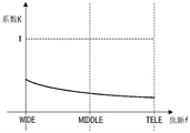
Fig. 14 is a diagram showing a relationship between the focal length and the coefficient K. In the same state as fig. 13, the abscissa axis represents the focal length f, and the ordinate axis represents the coefficient K for dividing the image shake correction amount. The coefficient K is determined by the movable range a of optical image shake correction and the movable range B of electronic image shake correction. In addition, since the optical image shake correction and the electronic image shake correction work separately, there is no boundary of the movable end of the optical image shake correction and the electronic image shake correction. As a result, image distortion due to overshoot of the optical image shake correction can be suppressed.
A description will be given specifically of the wide-angle end, the intermediate position, and the telephoto end shown in fig. 14. In the optical image shake correction, the image shake correction lens is moved within the movable range a, and in the electronic image shake correction, image processing is performed within the movable range B. Using these corrections together helps to correct image shake corresponding to the movable range of the entire image shake correction. As an example, the movable ranges a of the optical image shake correction are set to (2,0.75 and 0.3) at the wide-angle end, the intermediate position, and the telephoto end, respectively. The movable ranges B of the electronic image shake correction are set to (2.5, 1.6, 1.1) at the wide-angle end, the intermediate position, and the telephoto end, respectively. The movable ranges a and B are in degrees. In this case, the values of the coefficient K are (0.444, 0.319, 0.214) at the wide-angle end, the intermediate position, and the telephoto end, respectively.
If the second mode in which the optical image shake correction and the electronic image shake correction are performed is set, the driving of the correction lens is performed by the image shake correction amount that is the result of the multiplication of K = a/(a + B), and the cut-out position of the image pickup is changed by the image shake correction amount that is the result of the multiplication of the coefficients "1-K". On the other hand, if the first mode in which only the optical image shake correction is performed is set, the dividing unit 205 sets the value of the coefficient K to 1. That is, the drive control of the correction lens is performed in the total amount of the image shake correction amount serving as the optical image shake correction amount. Since electronic image shake correction is not performed, the values of the coefficients "1-K" relating to the amount of electronic image shake correction are zero.
Next, a description will be given of still image shooting in the second mode. If the second switch SW2 is turned on by an operation of the shutter release button of the camera operation unit 121, a still image exposure operation is performed. The dividing unit 205 sets the value of the coefficient K to 1. The total amount of the image shake correction amount is used as an optical image shake correction amount. Since electronic image shake correction is not performed during exposure of a still image, the values of the coefficients "1-K" relating to the amount of electronic image shake correction are zero. At the end of the still image exposure operation, the dividing unit 205 sets a coefficient of K = a/(a + B) in the optical image shake correction, and sets a coefficient "1-K" by the electronic image shake correction. Note that, at the start and end of the exposure operation of the still image, processing for providing a predetermined output time and gradually changing the correction output is performed to avoid an abrupt change in the correction amount of the optical image shake correction and the correction amount of the electronic image shake correction.
Fig. 3 is a block diagram showing the configuration of the electronic image shake correction control unit 123 in detail. The camera communication control unit 125 receives the electronic image shake correction amount from the lens unit via communication. The electronic image shake correction amounts in the pitch direction and the yaw direction are sent to be used as correction amounts that have been converted into angles. The pixel conversion unit 301 converts the electronic image shake correction amount into a pixel conversion correction amount (the number of pixels), and outputs the result to the limiter 305. The conversion coefficient has a different value for each focal length, and changes every time the focal length changes.
The camera shake detection unit 122 has a gyro sensor in the roll direction, and outputs a detection signal to the high-pass filter 302. The high-pass filter 302 removes offset and drift components of the detection signal. Further, the low-pass filter 303 cuts high-frequency noise of the detection signal. The pixel conversion unit 304 converts the angle conversion data into a pixel conversion correction amount, and outputs the result to the limiter 305, as in the pixel conversion unit 301.
The limiter 305 performs clamping in the cut-out range of the electronic image shake correction. The limiter 305 performs processing on respective outputs of the pixel conversion unit 301 and the pixel conversion unit 304. That is, the respective levels of the limiter are set for each of the pitch direction, yaw direction, and roll direction. The correction amount after the limiting process is input to the electronic image shake correction amount setting unit 306. The electronic image shake correction amount setting unit 306 sets the respective electronic image shake correction amounts in the respective correction axis directions.
First embodiment
A first embodiment of the present invention will be described below. A description will be given of lens communication performed between the lens communication control unit 112 and the camera communication control unit 125 and the timing thereof with reference to fig. 4. In order to perform optical image shake correction and electronic image shake correction, it is necessary to transmit the exposure center timing (406) of the image pickup unit 115 from the camera body to the lens unit. However, in addition to image shake correction, a large amount of communication for AF (auto focus adjustment), AE (auto exposure), and the like is performed between the camera body and the lens unit. A case where there is a variation in communication timing due to overlapping with another communication and communication of accurate exposure center timing is impossible may affect the processing. Therefore, in the present embodiment, in order to avoid the deviation of the communication timing, the communication process is performed twice, that is, the camera body transmits the exposure center timing to the lens unit by dividing the timing into the base point time and the relative time.
Further, when a large amount of information is received and transmitted by communication between the camera body and the lens, it becomes difficult to complete the processing within a specified time. Further, in order to be compatible with various interchangeable lenses, control is required without being aware of individual lens specifications. Therefore, in the present embodiment, control is performed by the lens unit serving as a main unit, and communication of angle conversion data for image shake correction is performed.
"VD" shown in fig. 4 denotes the timing of the vertical synchronization signal, and "V _ BLK" denotes the timing of the vertical blanking period. "CMOS drive" indicates a driving state of the image pickup element, and the lowermost line indicates communication between the camera body (C) and the lens unit (L). This indicates the communication timing 404 of the first communication 401, the timing 405 of determining the exposure time, and the exposure center timing 406, respectively. F [ n ] is an index representing the nth frame. The respective times shown in fig. 4 are as follows.
BT: length of vertical blanking period
IT: image time
AT: time from first communication timing 404 to timing 405
ET: exposure time
DT: delay time from midpoint of exposure period to exposure center timing 406
Based on the center of the exposure period, an exposure center timing 406 using the timing 405 as a reference is calculated with "IT + BT-ET/2+ DT". Note that, in each frame, the center of gravity of the parallelogram corresponds to the exposure center timing 406, and the area of the parallelogram becomes smaller as the exposure amount decreases. Reading of the signal of the image pickup element is started at a point of time (upper right vertex of the parallelogram) when the exposure time ET elapses from the exposure start point (upper left vertex of the parallelogram).
The first communication 401 from the camera body to the lens unit is performed with the vertical synchronization signal of the image capturing unit 115 as a starting point. The first communication 401 serves as a reference for transmitting the exposure center timing 406 from the camera body to the lens unit. At the timing of receiving information through the first communication 401, the lens unit obtains the timer time in the lens unit and sets the time as a base point for calculating the exposure center timing. Note that with regard to the communication timing 404 of the first communication 401, the communication may be performed at the same timing as the vertical synchronization signal, or may be performed before or after any time with respect to the vertical synchronization signal. However, communication is performed with a fixed time difference with respect to the vertical synchronization signal for each frame. In addition, the first communication timing 404 is a timing that does not overlap with another communication. In the example shown in fig. 4, the first communication timing 404 is set at a timing earlier (past) than the vertical synchronization signal.
Next, a second communication 402 is performed from the camera body to the lens unit. In the second communication 402, information on a relative time 407 from the first communication timing 404 with the first communication 401 as a reference is transmitted to the lens unit. In addition, in the second communication 402, the movable range B of electronic image shake correction for the current focal length is transmitted. The communication timing of the second communication 402 is after the timing 405 of determining the exposure time of the corresponding frame of the transmission exposure center. Therefore, even if the exposure time varies in each frame, the accurate exposure center timing 406 can be transmitted to the lens unit. The exposure center timing 406 is determined based on the determined exposure time and the signal readout time of the image pickup element, and the relative time 407 is determined based on the difference using the communication timing 404 of the first communication 401 as a reference. That is, relative time 407 is calculated by "AT + IT + BT-ET/2+ DT". Note that the timing 405 of determining the exposure time in each frame is not necessarily fixed.
The lens unit receives information on the relative time 407 in the second communication 402, which uses the reception timing of the first communication 401 as a reference. Therefore, the exposure center timing 406 can be grasped by timer setting in the lens unit. In addition, the lens unit receives the movable range B of electronic image shake correction through the second communication 402, and the coefficient K for the dividing unit 205 can be calculated by the movable range a of optical image shake correction including the lens itself. In the lens unit, at the exposure center timing 406, the lens shake detection unit 110 detects shake information, and the division unit 205 further allocates the total amount of the image shake correction amount to the optical image shake correction amount in the lens unit and the electronic image shake correction amount in the camera body. The lens system control unit 111 holds the electronic image shake correction amount that has been allocated in the memory until a communication request is provided from the camera system control unit 124.
In addition, a third communication 403 is performed from the camera body to the lens unit. In the third communication 403, after receiving a communication request from the camera system control unit 124, the lens system control unit 111 transfers the allocated electronic image shake correction amount to the camera system control unit 124. The communication timing of the third communication 403 is after the exposure center timing 406. Initially, the camera system control unit 124 grasps the exposure center timing 406, and therefore, communication is performed at any timing after the exposure center timing. In the camera body, the electronic image shake correction amount received from the lens system control unit 111 is transferred to the electronic image shake correction control unit 123, and finally, the electronic image shake correction amount setting unit 306 sets the correction amount.
The first communication to the third communication are performed in each frame, and the camera system control unit 124 reports the base point to the lens system control unit 111 through the first communication 401. The camera system control unit 124 reports the relative time with respect to the base point and the movable range of electronic image shake correction through the second communication 402. Through the third communication 403, the camera system control unit 124 obtains an electronic image shake correction amount from the lens system control unit 111. On the other hand, the lens system control unit 111 obtains a base point through the first communication 401 in each frame, obtains a relative time 407 with respect to the base point and a movable range of electronic image shake correction through the second communication, and distributes an electronic image shake correction amount of the exposure center timing 406. The lens system control unit 111 reports the allocated electronic image shake correction amount to the camera system control unit 124 through the third communication 403.
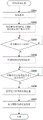
A description will be given of the processing of the present embodiment with reference to fig. 5 and 6. Fig. 5 is a flowchart related to communication and control content performed by the camera system control unit 124. Fig. 6 is a flowchart related to communication and control content performed by the lens system control unit 111. The following processing is realized according to a predetermined program read out from the memory and executed by the CPU of each control unit.
The main unit of the processing shown in fig. 5 is a camera system control unit 124, and communication processing is performed between the camera system control unit 124 and the lens system control unit 111 via a camera communication control unit 125 and a lens communication control unit 112. In S101, the camera system control unit 124 performs first communication 401 to the lens system control unit 111. The first communication timing serves as a base point with respect to the exposure center timing 406. Next, in S102, the second communication 402 is performed. The exposure center timing 406 is transmitted by transmitting a relative time 407 with respect to a base point in the first communication 401. Subsequently, the movable range of electronic image shake correction for the current focal length is transmitted.
In S103, the camera system control unit 124 determines whether a fixed time has elapsed from the exposure center timing 406. The fixed time is a time preset from the exposure center timing 406. If a fixed time has elapsed from the exposure center timing 406, the process proceeds to S104, and if not, the process returns to S103 and the process is repeated. The reason why the fixed time is waited to elapse in S103 is: so that the communication request of the camera system control unit 124 to the lens system control unit 111 is executed in a state where the lens system control unit 111 has completed the control processing of the exposure center timing 406.
In S104, the camera system control unit 124 performs third communication, and obtains the electronic image shake correction amount allocated by the lens system control unit 111 at the exposure center timing 406. In the following S105, the camera system control unit 124 provides an instruction to the electronic image shake correction control unit 123, and performs an image shake correction operation based on the electronic image shake correction amount obtained in S104.
The main unit of the processing shown in fig. 6 is a lens system control unit 111, and communication processing is performed between the lens system control unit 111 and a camera system control unit 124 via a lens communication control unit 112 and a camera communication control unit 125. In S201, the lens system control unit 111 accepts the first communication 401. At the first communication timing 404, a process of obtaining a timer time in the lens unit, which is used as a base point for calculating the exposure center timing, is performed.
Next, in S202, the lens system control unit 111 accepts the second communication 402, and obtains the relative time 407 with respect to the base point of the first communication timing 404 and the movable range of electronic image shake correction. Since the lens system control unit 111 has obtained the base point at the first communication timing 404, it receives the relative time 407 in the second communication, and sets the exposure center timing by timer setting. In addition, the lens system control unit 111 obtains a movable range of electronic image shake correction. In the case of a movable range including this movable range and optical image shake correction of the lens unit itself, the coefficient K used by the dividing unit 205 is calculated, and respective correction amounts relating to the optical image shake correction and the electronic image shake correction are set.
In S203, the lens system control unit 111 determines whether or not the exposure center timing at which the timer setting is executed in S202 has occurred. If the exposure center timing 406 occurs, the process proceeds to S204, and if the exposure center timing 406 does not occur, the determination process of S203 is repeated.
In S204, the lens system control unit 111 obtains shake information from the lens shake detection unit 110 at the exposure center timing 406, and the division unit 205 allocates the total amount of image shake correction amount to the optical image shake correction amount and the electronic image shake correction amount according to the value of the coefficient K. The lens system control unit 111 temporarily stores the allocated electronic image shake correction amount until a communication request is provided from the camera system control unit 124.
In S205, the lens system control unit 111 determines whether there is a communication request of the third communication 403 from the camera system control unit 124. If there is a communication request of the third communication, the process proceeds to S206, and if not, the determination process of S205 is repeated. In S206, the lens system control unit 111 accepts the third communication, and reports the electronic image shake correction amount allocated in S204 to the camera system control unit 124. In the present embodiment, the timing information on the exposure time period is not transmitted by one-time communication, and the base point and the relative time are reported from the camera body to the lens unit by the first communication and the second communication, respectively. Therefore, even if the communication timing of the second communication changes due to the influence of another communication, the base point of the first communication and the relative time of the second communication are transmitted to the lens unit, and as a result, accurate exposure center timing can be transmitted.
In addition, even if the first communication overlaps with another communication and the communication is delayed, the relative time of the second communication may be set in consideration of the delay time when the first communication is issued. That is, the exposure center timing may be reported by information on the relative time corrected based on the delay time. Therefore, even if the communication timing of the first communication is changed, more accurate exposure center timing can be transmitted from the camera body to the lens unit. The movable range of electronic image shake correction and the amount of electronic image shake correction are reported by using the angle conversion data. The camera system control unit 124 transmits the movable range of electronic image shake correction to the lens system control unit 111, and obtains an electronic image shake correction amount from the lens system control unit 111. According to the present embodiment, in the interchangeable lens imaging system, it is possible to perform image shake correction while avoiding communication timing deviation caused by overlap of communication performed between the lens unit and the main body. An image pickup system may be provided: optical image shake correction and electronic image shake correction are cooperatively controlled with a small amount of communication without the need for the user to know the specifications of the respective lenses and cameras, and the image shake correction range is expanded.
Second embodiment
Next, a second embodiment of the present invention will be described. In the present embodiment, the same reference numerals are used for the same components as those of the first embodiment of the present invention, and detailed description thereof is omitted, and points different from the first embodiment are mainly described. In the embodiments described below, such omission is also made.
In the first embodiment, after the camera system control unit 124 transmits timing information of the exposure time period to the lens system control unit 111, the lens system control unit 111 obtains an electronic image shake correction amount that is distributed at the exposure center timing. In the present embodiment, in addition to the assignment object, correction of the correction axis direction (roll direction) is performed by using the detection result of the camera shake detection unit 122, so that the image shake correction effect can be further enhanced.
The control contents of the present embodiment will be described with reference to the flowchart of fig. 7. Fig. 7 shows a control example including a communication process and a shake detection process in the camera body. First, in S301, the camera system control unit 124 performs first communication with the lens system control unit 111 via the camera communication control unit 125. The time of the first communication timing is used as a base point of the exposure center timing. Next, in S302, the camera system control unit 124 performs second communication via the camera communication control unit 125. The following processing is performed: the first communication is used as a base point, a relative time with respect to the base point is transmitted, and the exposure center timing is transmitted, and the movable range of electronic image shake correction of the current focal length is transmitted.
In S303, the camera system control unit 124 determines whether exposure center timing occurs by timer setting. If it is determined that the exposure center timing has occurred, the process proceeds to S304, and if it is determined that the exposure center timing has not occurred, the determination process of S303 is repeated. In S304, the camera system control unit 124 obtains shake information about the camera body detected by the camera shake detection unit 122 at the exposure center timing. The shake information detected here is shake information of a correction axis different from the correction axis related to the electronic image shake correction amount obtained from the lens system control unit 111 in S306 to be described below, that is, information about sensors having different detection directions.
In S305, the camera system control unit 124 determines whether a fixed time has elapsed from the exposure center timing. The process proceeds to S306 if it is determined that the fixed time has elapsed from the exposure center timing, and the determination process of S305 is repeated if it is determined that the fixed time has not elapsed. The reason why the elapse of the fixed time is waited for in S305 is as described in S103 in fig. 3. In S306, the camera system control unit 124 performs third communication with the lens system control unit 111 via the camera communication control unit 125. The camera system control unit 124 obtains an electronic image shake correction amount that the lens system control unit 111 assigns at the exposure center timing. In S307, the camera system control unit 124 provides an instruction to perform image shake correction control to the electronic image shake correction control unit 123. The electronic image shake correction control unit 123 performs image shake correction based on the shake information about the camera body detected in S304 and the electronic image shake correction amount obtained in S306.
In the present embodiment, image shake correction control is performed by obtaining the electronic image shake correction amount and the shake information about the camera body distributed by the lens system control unit 111. The electronic image shake correction amount is a correction amount relating to the pitch direction and the yaw direction, and shake information relating to the camera body is shake detection information in the correction axis direction (roll direction) that is not the distribution target. Therefore, electronic image shake correction in the three-axis direction is performed, and as a result, the image shake correction effect can be further enhanced.
Third embodiment
Next, a third embodiment of the present invention will be described. In the first embodiment, the camera system control unit 124 transmits the exposure center timing and the movable range of electronic image shake correction to the lens system control unit 111. The lens system control unit 111 transmits the electronic image shake correction amount that has been distributed to the camera system control unit 124. In the present embodiment, the lens system control unit 111 simultaneously transmits the positional information of the optical image shake correction to the camera system control unit 124 at the transmission timing of the electronic image shake correction amount. Therefore, setting of the correction center of the electronic image shake correction, inclination and shift correction, and the like can be performed, and as a result, the image shake correction effect can be further enhanced.
Referring to the flowchart in fig. 8, the control content of the present embodiment will be described. Since the respective processes from S401 to S403 are the same as those from S101 to S103 in fig. 5. Therefore, a description thereof will be omitted. A description will be given of S404 and S405.
In S404, the camera system control unit 124 performs third communication with the lens system control unit 111. The camera system control unit 124 obtains the electronic image shake correction amount that the lens system control unit 111 distributes at the exposure center timing of the lens system and the positional information about the image shake correction unit 105 at the exposure center timing. In the following S405, the camera system control unit 124 supplies the electronic image shake correction control unit 123 with an instruction to perform image shake correction based on the electronic image shake correction amount obtained in S404 and the position information of the image shake correction unit 105. This enables the matching setting of the correction center of the electronic image shake correction with respect to the optical axis center using the positional information on the image shake correction unit 105, so that more accurate correction can be performed. Further, the optical image shake correction amount can be understood from the positional information on the image shake correction unit 105. Therefore, by performing inclination and shift correction and the like together with the electronic image shake correction amount, the effect of correcting image shake can be further enhanced.
Fig. 9 is a flowchart related to communication and control content of a correction position including optical image shake correction of the lens unit. Since each process from S501 to S503 is the same as the process from S201 to S203 in fig. 6, a description thereof will be omitted. A description will be given of S504 to S506.
In S504, the lens system control unit 111 obtains shake information from the lens shake detection unit 110 at the exposure center timing, and obtains the position of the image shake correction unit 105 from the position detection unit 209. Further, the dividing unit 205 allocates the total amount of the image shake correction amount to the optical image shake correction amount and the electronic image shake correction amount. The lens system control unit 111 temporarily stores the electronic image shake correction amount that has been allocated and the detected positional information about the image shake correction unit 105 until a communication request is provided from the camera system control unit 124.
In S505, the lens system control unit 111 determines whether there is a communication request of the third communication from the camera system control unit 124 via the lens communication control unit 112. If there is a communication request, the process proceeds to S506, and if there is no communication request, the determination process of S505 is repeated. In S506, the lens system control unit 111 accepts a communication request of the third communication via the lens communication control unit 112, and reports the electronic image shake correction amount allocated in S504 and the position information about the image shake correction unit 105 detected in S504 to the camera system control unit 124.
In the present embodiment, the lens control unit transmits position information relating to optical image shake correction to the camera control unit at the timing of transmitting the electronic image shake correction amount. According to the present embodiment, setting of the correction center of electronic image shake correction, inclination and shift correction, and the like can be performed, and as a result, the image shake correction effect can be further enhanced.
Fourth embodiment
Next, in a fourth embodiment of the present invention, correction to rolling shutter distortion (hereinafter referred to as "RS distortion") serving as another type of electronic correction will be described. The exposure method of the image pickup unit 115 has a global shutter system and a rolling shutter system. In an apparatus using a global shutter system represented by a CCD (charge coupled device) image sensor, an exposure time and an exposure start time between pixels in one frame image are substantially the same. In an apparatus including a CMOS (complementary metal oxide semiconductor) image sensor, a rolling shutter method is used as an exposure method.
In the rolling shutter system in which the exposure timing differs for each pixel row, image distortion (RS distortion) occurs due to the deviation of the exposure timing and the signal readout time for each row. The shake of the image pickup apparatus affects signal reading of each line, and RS distortion occurs. Even if the image pickup apparatus is mounted to a tripod or the like, RS distortion occurs if vibration is applied to the apparatus due to disturbance such as wind or the like. RS distortion is distortion occurring in image capturing due to exposure timing differing for each pixel row, so that correction can be performed using the movement amount of each pixel row as a correction amount based on a shake signal of the image capturing apparatus.
A description will be given of RS distortion correction with reference to the conceptual diagram of fig. 15. By assuming a case where the image pickup apparatus is moved in the horizontal direction, an image 1501 before occurrence of RS distortion (a rectangular frame of a dotted line) and an image 1502 after occurrence of RS distortion (a parallelogram frame of a solid line) are shown. In the figure on the right, the amount of movement (shake amount) in the horizontal direction of the image pickup apparatus generated during the exposure period is exemplified by a plurality of points 1503. The horizontal axis represents pixel position and the vertical axis corresponds to the time axis. In the example shown 11 points are shown.
In the image pickup apparatus, a movement amount (shake amount) in the horizontal direction of the apparatus generated during an exposure period is calculated at a plurality of points. The amount of movement of each line is obtained by interpolation between a plurality of points to be used as a correction amount, and correction processing is performed by changing the readout position of each line for shake in the horizontal direction. That is, the lens shake detection unit 110 (fig. 2) detects a shake causing RS distortion. The video image signal processing unit 117 electronically performs RS distortion correction. Similarly to the case of the electronic image shake correction amount, calculation of a correction amount for correcting RS distortion is performed by the dividing unit 205, and the image shake correction amount is multiplied by the coefficients "1-K". The camera communication control unit 125 (fig. 3) obtains an RS distortion correction amount from the lens unit. The pixel conversion unit 301 converts the electronic image shake correction amount sent by the angle conversion into a pixel conversion value. The conversion coefficient used at this time has a different value for each focal length and changes every time the focal length changes. Further, the limiter 305 performs clipping in a movable range of RS distortion correction. Limit values for respective correction axis directions are set. The electronic image shake correction amount setting unit 306 sets RS distortion correction amounts in the respective correction axis directions.
Next, with reference to fig. 10, communication related to RS distortion correction performed between the lens communication control unit 112 and the camera communication control unit 125 and the timing thereof will be described. VD, V _ BLK, etc. are the same as in fig. 4. To perform RS distortion correction, the exposure center timing (1009) of the image capturing unit 115 needs to be transferred from the camera body to the lens unit. Since there are a plurality of correction points in RS distortion correction, the time difference between the correction timing and the correction point is transmitted first. Further, in the present embodiment, in order to avoid the deviation of the communication timing, communication is performed twice, once for the base point and once for the relative time. In fig. 10, a first communication 1001 is illustrated by a communication timing 1004. The second communication 1002 is after the timing 1005 at which the exposure time of the corresponding frame of the exposure center is determined. The process of the first correction timing 1006 for transmitting the RS distortion correction is performed. This control is performed by the lens system control unit 111 serving as a main unit, and communication is performed using angle conversion data for RS distortion correction.
The camera system control unit 124 performs the first communication 1001 to the lens system control unit 111 by using the vertical synchronization signal (reference VD) of the image capturing unit 115 as a starting point. The time of the first communication timing 1004 becomes a base point for transmitting the first correction timing 1006 of the RS distortion correction from the camera system control unit 124 to the lens system control unit 111. At the timing when the first communication 1001 has been accepted, the lens system control unit 111 obtains the internal timer time, and this time is used as a base point for calculating the first correction timing of the RS distortion correction. Note that the communication timing 1004 of the first communication 1001 may be the same timing as the vertical synchronization signal, or may be any time before or after with respect to the vertical synchronization signal. However, it is assumed that communication is performed with a fixed time difference with respect to the vertical synchronization signal for each frame. In addition, it is desirable that the first communication timing 1004 does not overlap with another communication. In the example of fig. 10, the communication timing 1004 of the first communication 1001 is set at a timing before the vertical synchronization signal.
Next, the camera system control unit 124 performs the second communication 1002. In the second communication 1002, the relative time 1007 with respect to the base point is transmitted to the lens system control unit 111 by taking the time of the first communication 1001 as the base point. The time difference 1008 is a time difference between correction points of RS distortion correction. The camera system control unit 124 transmits the time difference 1008 between the correction point of the RS distortion correction and the movable range B of the electronic image shake correction of the current focal length to the lens system control unit 111. The second communication 1002 is after the timing 1005 at which the exposure time of the corresponding frame of the first correction timing 1006 of the RS distortion correction is determined. Therefore, even if the exposure time varies in each frame, the accurate first correction timing 1006 of the RS distortion correction can be transmitted. The first correction timing 1006 of RS distortion correction is obtained based on the determined exposure time and the readout time of the image pickup element signal, and the relative time 1007 is obtained from the difference with respect to the base point through the first communication 1001.
The lens system control unit 111 has obtained a base point at the timing of accepting the first communication 1001. Thus, the relative time 1007 is obtained through the second communication 1002, and the lens system control unit 111 can set the first correction timing 1006 of the RS distortion correction by the internal timer setting. In addition, the lens system control unit 111 obtains the movable range B of the electronic image shake correction, so that the lens system control unit 111 can calculate the coefficient K used in the dividing unit 205 with the movable range a of the optical image shake correction of the lens unit included. The lens system control unit 111 obtains shake information from the lens shake detection unit 110 at the first correction timing 1006 of the RS distortion correction. The dividing unit 205 multiplies the image shake correction amount by the coefficients "1-K", and calculates an RS distortion correction amount. The lens system control unit 111 holds the RS distortion correction amount until a communication request is provided from the camera system control unit 124.
In addition, the lens system control unit 111 sets the next RS distortion correction timing by an internal timer setting. In the setting of the next RS distortion correction timing, the lens system control unit 111 uses the time difference 1008 between the correction points of the RS distortion correction and the correction timing of the current RS distortion correction. The timer setting is repeatedly performed until the total correction timing of the RS distortion correction ends. In fig. 10, since there are 11 correction points of RS distortion correction, the sixth correction point from the first correction timing 1006 corresponds to the exposure center. That is, the timing information of the exposure time period includes information on the exposure center timing 1009. Also at the exposure center timing 1009, the lens system control unit 111 obtains an electronic image shake correction amount.
Finally, the camera system control unit 124 performs third communication 1003 on the lens system control unit 111. In the third communication 1003, the lens system control unit 111 accepts a communication request from the camera system control unit 124, and transmits the held RS distortion correction amount. The communication timing of the third communication 1003 is after the final correction timing 1010 of the RS distortion correction. The final correction timing 1010 corresponds to an eleventh correction point. Since the camera system control unit 124 has already grasped the RS distortion correction timing initially, communication is performed at any timing after the final correction timing 1010 of the RS distortion correction. The camera system control unit 124 sends the RS distortion correction amount obtained from the lens system control unit 111 to the electronic image shake correction control unit 123, and finally sets it to the electronic image shake correction amount setting unit 306.
The camera system control unit 124 reports a base point in the first communication 1001 and a relative time with respect to the base point and a movable range of electronic image shake correction in the second communication 1002, and receives an RS distortion correction amount in the third communication 1003, performing the first communication to the third communication for each frame. The lens system control unit 111 obtains a base point through the first communication 1001, and obtains the first correction timing of the RS distortion correction based on the relative time with respect to the base point and the movable range of the electronic image shake correction through the second communication 1002. The lens system control unit 111 calculates correction amounts of the respective RS distortion correction timings, and reports the results to the camera system control unit 124 in the third communication 1003.
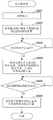
A description will be given of the communication and control contents including the RS distortion correction performed by the camera system control unit 124 with reference to the flowchart of fig. 11. First, in S601, the camera system control unit 124 performs first communication to the lens system control unit 111 via the camera communication control unit 125. The time according to the first communication is used as a base point of the first correction timing 1006 of the RS distortion correction. Next, in S602, the camera system control unit 124 performs second communication to the lens system control unit 111 via the camera communication control unit 125. A relative time 1007 with respect to the base point is transmitted using the time according to the first communication as the base point, and the first correction timing 1006 of the RS distortion correction is transmitted to the lens system control unit 111. The camera system control unit 124 transmits the time difference between the correction points of the RS distortion correction and the movable range of electronic image shake correction of the current focal length to the lens system control unit 111.
In S603, the camera system control unit 124 determines whether a fixed time has elapsed from the final correction timing 1010 of the RS distortion correction. The fixed time is a preset time. If the fixed time has elapsed from the final correction timing 1010 of the RS distortion correction, the process proceeds to S604, and if the fixed time has not elapsed, the determination process of S603 is repeated. The reason why the fixed time is waited for in S603 is: in a state in which the lens system control unit 111 has completed processing of the final correction point of the RS distortion correction, a communication request to the lens system control unit 111 is executed by the camera system control unit 124.
In S604, the camera system control unit 124 performs third communication to the lens system control unit 111 via the camera communication control unit 125. The camera system control unit 124 obtains an electronic image shake correction amount and an RS distortion correction amount at each of a plurality of correction points of RS distortion correction, which are distributed at the exposure center timing 1009 by the lens system control unit 111. In S605, the camera system control unit 124 provides an instruction to the electronic image shake correction control unit 123 to perform image correction based on the electronic image shake correction amount and the RS distortion correction amount obtained in S604.
A description will be given of communication and control contents including RS distortion correction performed by the lens system control unit 111 with reference to a flowchart in fig. 12. First, in S701, the lens system control unit 111 accepts first communication from the camera system control unit 124 via the lens communication control unit 112. The lens system control unit 111 obtains the internal timer time at the first communication timing, and this time is used as a base point for calculating the first correction timing of the RS distortion correction.
Next, in S702, the lens system control unit 111 accepts second communication from the camera system control unit 124 via the lens communication control unit 112. The lens system control unit 111 obtains a relative time with respect to the base point, a time difference between correction points of RS distortion correction, and a movable range of electronic image shake correction. Since the lens system control unit 111 has obtained the time of the first communication timing 1004 as a base point, it receives the relative time 1007 through the second communication 1002 and sets the first correction timing of RS distortion correction by the internal timer setting. In addition, the lens system control unit 111 receives the movable range of electronic image shake correction, and calculates and sets the coefficient K used in the dividing unit 205 in the case where the movable range of optical image shake correction of the lens unit is included.
In S703, the lens system control unit 111 determines whether correction timing of RS distortion correction has occurred. The process proceeds to S704 if the lens system control unit 111 determines that the correction timing of the RS distortion correction has occurred, and repeats the determination process of S703 if it determines that the correction timing of the RS distortion correction has not occurred. In S704, the lens system control unit 111 obtains shake information from the lens shake detection unit 110 at the correction timing of the RS distortion correction. In addition, the dividing unit 205 calculates an optical image shake correction amount and a correction amount of RS distortion correction of the lens unit. The lens system control unit 111 temporarily stores the RS distortion correction amount until a communication request is provided from the camera system control unit 124. Note that if there are 11 correction points of RS distortion correction, the sixth correction point from the beginning corresponds to the exposure center. The lens system control unit 111 obtains an electronic image shake correction amount even at the exposure center timing 1009.
In S705, the lens system control unit 111 determines whether all correction timings of RS distortion correction have occurred. If all the correction timings of the RS distortion correction have occurred, the process proceeds to S707, and if all the correction timings of the RS distortion correction have not occurred, the process proceeds to S706. In S706, the lens system control unit 111 sets the next correction timing of the RS distortion correction by the internal timer setting. In the setting of the next correction timing, the lens system control unit 111 uses the time difference between the correction points of the RS distortion correction obtained in S702 and the current correction timing of the RS distortion correction. After the timer is set, the process returns to S703.
In S707, the lens system control unit 111 determines whether a communication request for the third communication is provided from the camera system control unit 124 via the lens communication control unit 112. If a communication request for the third communication is provided, the process proceeds to S708, and if no communication request is provided, the determination process of S707 is repeated. In S708, the lens system control unit 111 accepts third communication from the camera system control unit 124 via the lens communication control unit 112. The lens system control unit 111 reports the electronic image shake correction amount and the RS distortion correction amount for each of the plurality of correction points of RS distortion correction allocated at the exposure center timing to the camera system control unit 124.
In the present embodiment, the time difference between the correction points of the RS distortion correction and the first correction timing of the RS distortion correction are transmitted from the camera system control unit 124 to the lens system control unit 111. The lens system control unit 111 grasps the timing of each correction point of the RS distortion correction, and can obtain an RS distortion correction amount. The RS distortion correction amount is reported to the camera control unit, and RS distortion correction is performed. According to the present embodiment, in the interchangeable lens imaging system, it is possible to correct distortion of an image by avoiding communication timing deviation due to overlapping of communications.
The present embodiment describes a case where the camera control performs correction by using the RS distortion correction amount obtained from the lens control unit. The camera control unit performs RS distortion correction in the correction axis direction (roll direction) other than the obtained axis, which enables further enhancement of the image shake correction effect. Further, in the present embodiment, 11 points are shown in the illustrated example, serving as RS distortion correction points. The number of RS distortion correction points need not be fixed to a predetermined number, and may be changed in response to a communication speed that the lens unit can cope with, for example. In this case, the camera control unit obtains a communication speed compatible by communication with the lens unit, and reports the number of correction points of RS distortion correction to the lens control unit during the second communication. Accordingly, the number of correction points of the RS distortion correction to be obtained by the lens control unit is determined.
OTHER EMBODIMENTS
The embodiments of the present invention can also be realized by a method in which software (programs) that perform the functions of the above-described embodiments are supplied to a system or an apparatus through a network or various storage media, and a computer or a Central Processing Unit (CPU), a Micro Processing Unit (MPU) of the system or the apparatus reads out and executes the methods of the programs.
While the present invention has been described with reference to exemplary embodiments, it is to be understood that the invention is not limited to the disclosed exemplary embodiments. The scope of the following claims is to be accorded the broadest interpretation so as to encompass all such modifications and equivalent structures and functions.
This application claims priority from japanese patent application 2016-035020, filed on 26/2/2016, the entire contents of which are incorporated herein by reference.
Claims (30)
1. An image pickup apparatus for communicating with an interchangeable lens unit mounted thereon, comprising:
an image pickup unit;
a second communication unit for communicating with the interchangeable lens unit; and
a determination unit for determining a relative time,
wherein in the first communication, the second communication unit transmits information indicating a base point timing to the interchangeable lens unit,
wherein in the second communication, the second communication unit transmits information indicating the relative time determined by the determination unit to the interchangeable lens unit,
wherein the determination unit determines, as the relative time, a time length from a base point timing that has been transmitted in the first communication until an exposure center of the imaging unit, an
Wherein the relative time depends at least on the length of the exposure time.
2. The image pickup apparatus according to claim 1,
the information indicating the base point timing is information in which the timing of the vertical synchronization signal is used as a starting point.
3. The image pickup apparatus according to claim 1, further comprising:
an image shake correction unit for correcting image shake of an image; and
a control unit for controlling the image shake correction unit.
4. The image pickup apparatus according to claim 3,
wherein, in the third communication, the second communication unit receives an image shake correction amount from the interchangeable lens unit and reports the image shake correction amount to the control unit, an
Wherein the control unit controls the image shake correction unit according to the image shake correction amount.
5. The image pickup apparatus according to claim 1, further comprising:
a correction unit for correcting distortion of an image; and
a control unit for controlling the correction unit.
6. The image pickup apparatus according to claim 5,
the second communication unit transmits information about the first correction timing serving as the relative time to the interchangeable lens unit.
7. The image pickup apparatus according to claim 6,
in a case where the control unit performs control to correct distortion of an image with a plurality of correction points at different timings, the second communication unit transmits information on a time difference between the correction points to the interchangeable lens unit in the second communication.
8. The image pickup apparatus according to claim 1,
the determination unit determines the relative time by using a delay time when the first communication is issued.
9. The image pickup apparatus according to claim 1,
the second communication is performed after the length of the exposure time of the image pickup unit is determined.
10. The image pickup apparatus according to claim 1, wherein the relative time transmitted in the second communication starts from a base timing transmitted in the first communication.
11. An image pickup apparatus for communicating with an interchangeable lens unit mounted thereon, comprising:
an image pickup unit;
a second communication unit for communicating with the interchangeable lens unit; and
a determination unit configured to determine a difference between an exposure center of the imaging unit and a base point timing as a relative time,
wherein, in the first communication, the second communication unit transmits information indicating a base point timing to the interchangeable lens unit, an
Wherein in the second communication, the second communication unit transmits information indicating the relative time.
12. The image pickup apparatus according to claim 11,
in the third communication, the second communication unit receives, from the interchangeable lens unit, correction information for image shake correction obtained based on a shake detection signal obtained at a timing based on the base point timing and the relative time.
13. The image pickup apparatus according to claim 12,
the correction information is obtained by the interchangeable lens unit after a timing for obtaining a shake detection signal for image shake correction determined based on the information on the base point timing and the information on the relative time.
14. The image pickup apparatus according to claim 12,
the third communication is performed after the jitter detection signal is obtained.
15. An interchangeable lens unit mounted on an image pickup apparatus, the interchangeable lens unit comprising:
an image shake correction lens for correcting image shake in an image due to shake;
a first communication unit configured to communicate with the image pickup apparatus; and
a control unit for controlling the image shake correction lens,
wherein in the first communication, the first communication unit receives information indicating a base point timing from the image pickup apparatus,
wherein the first communication is repeatedly performed,
wherein in the second communication, the first communication unit receives information indicating a relative time from the image pickup apparatus,
wherein the control unit obtains correction information for image shake correction based on timing and controls the image shake correction lens based on the correction information, an
Wherein the timing is determined by a first base point timing represented by information received through one of the plurality of first communications and the relative time received in the second communication that is performed after receiving the information representing the first base point timing.
16. The interchangeable lens unit according to claim 15,
the information indicating the base point timing is information in which the timing of the vertical synchronization signal is used as a starting point.
17. The interchangeable lens unit according to claim 15,
wherein the relative time represents a length of time from the base point timing until an exposure center of the image pickup apparatus, an
Wherein the first communication unit receives the information representing the relative time after the exposure time period is determined.
18. The interchangeable lens unit according to claim 15,
the control unit obtains correction information for image shake correction performed in the image pickup apparatus, and performs control such that the first communication unit transmits the correction information to the image pickup apparatus in third communication.
19. The interchangeable lens unit according to claim 15,
the control unit obtains a correction amount of a correction unit that corrects distortion of an image included in the image pickup apparatus, and performs control in which the first communication unit transmits the correction amount to the image pickup apparatus in third communication.
20. The interchangeable lens unit according to claim 19,
in a case where the control unit performs control to correct distortion of an image with a plurality of correction points at different timings, the first communication unit receives information on a time difference between the correction points from the image pickup apparatus in the second communication, and obtains a correction amount of distortion of the image at the correction points.
21. The interchangeable lens unit according to claim 20,
in the third communication, the control unit performs control in which the first communication unit transmits the correction amount to the image pickup apparatus.
22. The interchangeable lens unit according to claim 15,
the control unit performs control of image shake correction by driving the image shake correction lens.
23. The interchangeable lens unit according to claim 15,
the control unit detects a shake at a timing determined by the base timing and the relative time, and obtains the correction information from the detected shake.
24. The interchangeable lens unit according to claim 15, wherein the timing is a timing at which the relative time has elapsed after receiving the information indicating the first base point timing.
25. The interchangeable lens unit according to claim 15, wherein the relative time is a length of time from the base point timing until an exposure center of the image pickup apparatus.
26. The interchangeable lens unit according to claim 15,
wherein the first communication is repeatedly performed, an
Wherein the second communication is between the repeated first communications.
27. An interchangeable lens unit mounted on an image pickup apparatus, the interchangeable lens unit comprising:
an image shake correction lens for correcting image shake in an image due to shake;
a first communication unit configured to communicate with the image pickup apparatus; and
a control unit for obtaining a shake detection signal and controlling the image shake correction lens,
wherein in the first communication, the first communication unit receives information indicating a base point timing from the image pickup apparatus,
wherein in the second communication, the first communication unit receives information indicating a relative time, which is a length of time from the base point timing until an exposure center of the image pickup apparatus, from the image pickup apparatus, and
wherein the control unit obtains a timing determined by the base point timing and the relative time, and obtains the shake detection signal at the timing.
28. An interchangeable lens unit according to claim 27, wherein in third communication, the first communication unit transmits correction information of image shake correction obtained based on a shake detection signal obtained at a timing based on the base point timing and the relative time to the image pickup apparatus.
29. An image pickup system includes a main body of an image pickup apparatus and an interchangeable lens unit,
the image pickup system includes:
an image pickup unit;
a first communication unit for communicating with a second communication unit included in the main body;
a correction unit for correcting image shake in an image due to shake;
a control unit for obtaining a shake detection signal and controlling the correction unit;
the second communication unit for communicating with the first communication unit included in the interchangeable lens unit; and
a determination unit for determining a relative time,
wherein, in the first communication, the second communication unit transmits information indicating a base point timing to the first communication unit,
wherein in the second communication, the second communication unit transmits information indicating the relative time determined by the determination unit to the first communication unit,
wherein the determination unit determines, as the relative time, a time length from a base point timing that has been transmitted in the first communication until an exposure center of the imaging unit, an
Wherein the relative time depends at least on the length of the exposure time.
30. A control method executed in an image pickup system including an interchangeable lens unit and a main body of an image pickup apparatus, the control method of the image pickup system comprising:
in the first communication, a second communication unit included in the main body transmits information representing a base point timing to a first communication unit included in the interchangeable lens unit;
determining a relative time by a determination unit; and
in the second communication, the second communication unit transmits information on the relative time with respect to the base point timing determined by the determination unit to the first communication unit,
wherein the determination unit determines, as the relative time, a length of time from a base point timing that has been transmitted in the first communication until an exposure center of an image pickup unit included in the image pickup apparatus, and
wherein the relative time varies with the length of the exposure time.
Applications Claiming Priority (3)
| Application Number | Priority Date | Filing Date | Title |
|---|---|---|---|
| JP2016035020A JP6700853B2 (en) | 2016-02-26 | 2016-02-26 | Imaging system and control method thereof, imaging device, and lens device |
| JP2016-035020 | 2016-02-26 | ||
| CN201710111846.6A CN107135349B (en) | 2016-02-26 | 2017-02-24 | Image pickup apparatus, lens unit, image pickup system, and control method thereof |
Related Parent Applications (1)
| Application Number | Title | Priority Date | Filing Date |
|---|---|---|---|
| CN201710111846.6A Division CN107135349B (en) | 2016-02-26 | 2017-02-24 | Image pickup apparatus, lens unit, image pickup system, and control method thereof |
Publications (2)
| Publication Number | Publication Date |
|---|---|
| CN112584046A CN112584046A (en) | 2021-03-30 |
| CN112584046B true CN112584046B (en) | 2022-11-29 |
Family
ID=59679948
Family Applications (2)
| Application Number | Title | Priority Date | Filing Date |
|---|---|---|---|
| CN202011432079.7A Active CN112584046B (en) | 2016-02-26 | 2017-02-24 | Image pickup apparatus, lens unit, image pickup system, and control method thereof |
| CN201710111846.6A Active CN107135349B (en) | 2016-02-26 | 2017-02-24 | Image pickup apparatus, lens unit, image pickup system, and control method thereof |
Family Applications After (1)
| Application Number | Title | Priority Date | Filing Date |
|---|---|---|---|
| CN201710111846.6A Active CN107135349B (en) | 2016-02-26 | 2017-02-24 | Image pickup apparatus, lens unit, image pickup system, and control method thereof |
Country Status (3)
| Country | Link |
|---|---|
| US (1) | US10904439B2 (en) |
| JP (1) | JP6700853B2 (en) |
| CN (2) | CN112584046B (en) |
Families Citing this family (11)
| Publication number | Priority date | Publication date | Assignee | Title |
|---|---|---|---|---|
| JP6674701B2 (en) * | 2016-09-28 | 2020-04-01 | ルネサスエレクトロニクス株式会社 | Image processing module and semiconductor system |
| JP7039263B2 (en) * | 2017-11-20 | 2022-03-22 | キヤノン株式会社 | Imaging system, imaging device, lens device, and its control method |
| CN108234873A (en) * | 2018-01-10 | 2018-06-29 | 北京小米移动软件有限公司 | A kind of method and apparatus for obtaining image |
| JP2019145956A (en) * | 2018-02-19 | 2019-08-29 | キヤノン株式会社 | Imaging apparatus, control method of the same, and program |
| CN108650459A (en) * | 2018-05-07 | 2018-10-12 | 深圳市宇眼科技有限公司 | A kind of law-enforcing recorder with optical anti-vibration function |
| CN108632579B (en) * | 2018-05-29 | 2020-10-27 | 广东小天才科技有限公司 | Alarm method and device, intelligent wearable device and storage medium |
| CN113170038B (en) * | 2018-11-29 | 2023-06-13 | 富士胶片株式会社 | Jitter correction control device, method for operating jitter correction control device, storage medium, and image pickup device |
| CN110536057B (en) * | 2019-08-30 | 2021-06-08 | Oppo广东移动通信有限公司 | Image processing method and device, electronic equipment and computer readable storage medium |
| JP2022042305A (en) * | 2020-09-02 | 2022-03-14 | キヤノン株式会社 | Image shake correction device and method for controlling the same, program, and storage medium |
| KR20220145621A (en) * | 2021-04-22 | 2022-10-31 | 삼성전자주식회사 | Method for Stabilization in shooting and Electronic Device thereof |
| CN113596294A (en) * | 2021-07-08 | 2021-11-02 | 维沃移动通信(杭州)有限公司 | Shooting method and device and electronic equipment |
Citations (8)
| Publication number | Priority date | Publication date | Assignee | Title |
|---|---|---|---|---|
| CN1892294A (en) * | 2005-07-01 | 2007-01-10 | 奥林巴斯映像株式会社 | Camera system equipped with camera shake correction function |
| CN101026691A (en) * | 2006-02-23 | 2007-08-29 | 奥林巴斯映像株式会社 | Electronic blurring compensation device |
| CN101322399A (en) * | 2006-02-14 | 2008-12-10 | 索尼株式会社 | Image pickup apparatus |
| JP2010271379A (en) * | 2009-05-19 | 2010-12-02 | Canon Inc | Imaging device |
| CN102016679A (en) * | 2008-03-28 | 2011-04-13 | 松下电器产业株式会社 | Camera system |
| CN102137234A (en) * | 2010-01-25 | 2011-07-27 | 奥林巴斯映像株式会社 | Image pickup apparatus |
| CN102647561A (en) * | 2011-02-21 | 2012-08-22 | 三星电子株式会社 | Photographing apparatus and photographing method thereof |
| CN104065868A (en) * | 2013-03-18 | 2014-09-24 | 佳能株式会社 | Image capture apparatus and control method thereof |
Family Cites Families (17)
| Publication number | Priority date | Publication date | Assignee | Title |
|---|---|---|---|---|
| JP3800230B2 (en) * | 2004-09-14 | 2006-07-26 | コニカミノルタフォトイメージング株式会社 | Imaging apparatus and flash synchronization speed setting method |
| US7702227B2 (en) * | 2005-08-16 | 2010-04-20 | Canon Kabushiki Kaisha | Optical device having blur correction function |
| JP2008070844A (en) * | 2006-09-15 | 2008-03-27 | Ricoh Co Ltd | Imaging apparatus |
| JP2008139640A (en) * | 2006-12-04 | 2008-06-19 | Canon Inc | Imaging apparatus |
| US8095000B2 (en) * | 2007-02-15 | 2012-01-10 | Panasonic Corporation | Camera system |
| KR101236605B1 (en) * | 2008-04-17 | 2013-02-22 | 파나소닉 주식회사 | Interchangeable lens, camera body, and camera system |
| JP5072764B2 (en) * | 2008-08-01 | 2012-11-14 | キヤノン株式会社 | Optical apparatus and camera system |
| JP4905598B2 (en) | 2011-04-25 | 2012-03-28 | 株式会社ニコン | Lens barrel |
| JP6045205B2 (en) * | 2012-06-07 | 2016-12-14 | キヤノン株式会社 | Imaging apparatus and control method thereof, and lens apparatus and control method thereof |
| JP5984574B2 (en) | 2012-08-14 | 2016-09-06 | キヤノン株式会社 | Imaging system, control method therefor, and imaging apparatus |
| JP6341691B2 (en) | 2014-02-26 | 2018-06-13 | キヤノン株式会社 | Image shake correction apparatus, control method therefor, optical apparatus, and imaging apparatus |
| JP2015194712A (en) * | 2014-03-28 | 2015-11-05 | パナソニックIpマネジメント株式会社 | Imaging apparatus |
| JP6438671B2 (en) * | 2014-04-10 | 2018-12-19 | オリンパス株式会社 | Focus adjustment apparatus, camera system, and focus adjustment method of imaging apparatus |
| US9749556B2 (en) * | 2015-03-24 | 2017-08-29 | Semiconductor Components Industries, Llc | Imaging systems having image sensor pixel arrays with phase detection capabilities |
| JP6466786B2 (en) * | 2015-06-12 | 2019-02-06 | オリンパス株式会社 | Imaging apparatus, imaging method, and program |
| JP6579609B2 (en) * | 2015-07-13 | 2019-09-25 | オリンパス株式会社 | Camera system, blur correction method thereof, and camera body |
| KR102441004B1 (en) * | 2015-09-04 | 2022-09-07 | 삼성전자주식회사 | Optical system |
-
2016
- 2016-02-26 JP JP2016035020A patent/JP6700853B2/en active Active
-
2017
- 2017-02-10 US US15/429,657 patent/US10904439B2/en active Active
- 2017-02-24 CN CN202011432079.7A patent/CN112584046B/en active Active
- 2017-02-24 CN CN201710111846.6A patent/CN107135349B/en active Active
Patent Citations (8)
| Publication number | Priority date | Publication date | Assignee | Title |
|---|---|---|---|---|
| CN1892294A (en) * | 2005-07-01 | 2007-01-10 | 奥林巴斯映像株式会社 | Camera system equipped with camera shake correction function |
| CN101322399A (en) * | 2006-02-14 | 2008-12-10 | 索尼株式会社 | Image pickup apparatus |
| CN101026691A (en) * | 2006-02-23 | 2007-08-29 | 奥林巴斯映像株式会社 | Electronic blurring compensation device |
| CN102016679A (en) * | 2008-03-28 | 2011-04-13 | 松下电器产业株式会社 | Camera system |
| JP2010271379A (en) * | 2009-05-19 | 2010-12-02 | Canon Inc | Imaging device |
| CN102137234A (en) * | 2010-01-25 | 2011-07-27 | 奥林巴斯映像株式会社 | Image pickup apparatus |
| CN102647561A (en) * | 2011-02-21 | 2012-08-22 | 三星电子株式会社 | Photographing apparatus and photographing method thereof |
| CN104065868A (en) * | 2013-03-18 | 2014-09-24 | 佳能株式会社 | Image capture apparatus and control method thereof |
Also Published As
| Publication number | Publication date |
|---|---|
| CN112584046A (en) | 2021-03-30 |
| JP6700853B2 (en) | 2020-05-27 |
| JP2017152996A (en) | 2017-08-31 |
| US20170251147A1 (en) | 2017-08-31 |
| CN107135349A (en) | 2017-09-05 |
| US10904439B2 (en) | 2021-01-26 |
| CN107135349B (en) | 2020-12-11 |
Similar Documents
| Publication | Publication Date | Title |
|---|---|---|
| CN112584046B (en) | Image pickup apparatus, lens unit, image pickup system, and control method thereof | |
| CN107135338B (en) | Image pickup system, control method thereof, image pickup apparatus, and lens device | |
| JP7277513B2 (en) | a lens device, a lens device control method, and a lens device control program; | |
| EP2187626B1 (en) | Image pickup apparatus and control method thereof | |
| JP6808399B2 (en) | Accessory device, control device, imaging system, communication control method and communication control program | |
| KR102393775B1 (en) | Camera controller, image processing module, and semiconductor system | |
| US20190222767A1 (en) | Shake correction device, imaging apparatus, and shake correction method | |
| CN107231513B (en) | Image pickup system, image pickup apparatus, lens device, and control method thereof | |
| JP2017219635A (en) | Image processing device and method, imaging device, and imaging system | |
| JP7218207B2 (en) | Camera, lens apparatus, control method, and computer program | |
| US11350036B2 (en) | Image pickup apparatus and lens device that have image blur correction function | |
| CN110418053B (en) | Lens apparatus, control method thereof, image pickup apparatus, and control method thereof | |
| US11202011B2 (en) | Control apparatus, image capturing apparatus, lens apparatus, image capturing system, control method, and storage medium | |
| JP7039263B2 (en) | Imaging system, imaging device, lens device, and its control method | |
| JP6800642B2 (en) | Accessory device, control device, control method of these | |
| JP7182962B2 (en) | IMAGING DEVICE, LENS DEVICE, AND CONTROL METHOD THEREOF | |
| JP6168827B2 (en) | Image stabilization apparatus and optical apparatus |
Legal Events
| Date | Code | Title | Description |
|---|---|---|---|
| PB01 | Publication | ||
| PB01 | Publication | ||
| SE01 | Entry into force of request for substantive examination | ||
| SE01 | Entry into force of request for substantive examination | ||
| GR01 | Patent grant | ||
| GR01 | Patent grant |