CN112582931A - Chassis car, handcart-type circuit breaker and cubical switchboard - Google Patents
Chassis car, handcart-type circuit breaker and cubical switchboard Download PDFInfo
- Publication number
- CN112582931A CN112582931A CN201910936652.9A CN201910936652A CN112582931A CN 112582931 A CN112582931 A CN 112582931A CN 201910936652 A CN201910936652 A CN 201910936652A CN 112582931 A CN112582931 A CN 112582931A
- Authority
- CN
- China
- Prior art keywords
- pushing piece
- circuit breaker
- chassis
- crank arm
- guide
- Prior art date
- Legal status (The legal status is an assumption and is not a legal conclusion. Google has not performed a legal analysis and makes no representation as to the accuracy of the status listed.)
- Pending
Links
- 230000000149 penetrating effect Effects 0.000 claims abstract description 26
- 230000009286 beneficial effect Effects 0.000 description 24
- 238000003780 insertion Methods 0.000 description 17
- 230000037431 insertion Effects 0.000 description 17
- 230000005540 biological transmission Effects 0.000 description 6
- 230000000694 effects Effects 0.000 description 6
- 238000010586 diagram Methods 0.000 description 4
- 230000000903 blocking effect Effects 0.000 description 3
- 230000002093 peripheral effect Effects 0.000 description 2
- 238000000926 separation method Methods 0.000 description 2
- 241001391944 Commicarpus scandens Species 0.000 description 1
- 238000005452 bending Methods 0.000 description 1
- 238000009434 installation Methods 0.000 description 1
- 238000003466 welding Methods 0.000 description 1
Images


Classifications
-
- H—ELECTRICITY
- H02—GENERATION; CONVERSION OR DISTRIBUTION OF ELECTRIC POWER
- H02B—BOARDS, SUBSTATIONS OR SWITCHING ARRANGEMENTS FOR THE SUPPLY OR DISTRIBUTION OF ELECTRIC POWER
- H02B11/00—Switchgear having carriage withdrawable for isolation
- H02B11/12—Switchgear having carriage withdrawable for isolation with isolation by horizontal withdrawal
- H02B11/167—Switchgear having carriage withdrawable for isolation with isolation by horizontal withdrawal truck type
-
- H—ELECTRICITY
- H02—GENERATION; CONVERSION OR DISTRIBUTION OF ELECTRIC POWER
- H02B—BOARDS, SUBSTATIONS OR SWITCHING ARRANGEMENTS FOR THE SUPPLY OR DISTRIBUTION OF ELECTRIC POWER
- H02B11/00—Switchgear having carriage withdrawable for isolation
- H02B11/02—Details
Abstract
The invention belongs to the technical field of circuit breakers, and relates to a chassis vehicle, a handcart type circuit breaker and a switch cabinet, which comprise the chassis vehicle and the circuit breaker arranged on the chassis vehicle, wherein the handcart type circuit breaker also comprises an emergency opening mechanism, and the emergency opening mechanism comprises: the rotating shaft is rotatably arranged on the chassis vehicle, one end of the rotating shaft is exposed out of the front side of the chassis vehicle, and the rotating shaft is provided with a crank arm; the pushing piece is limited on the chassis vehicle through the guide structure and extends vertically, and the pushing piece is perpendicular to the opening half shaft of the circuit breaker; one of the pushing piece and the crank arm is provided with a horizontally extending long groove, the other one is provided with a connecting pin, and the connecting pin is arranged in the long groove in a penetrating way to realize the connection of the pushing piece and the crank arm; a reset mechanism. When the electric brake-separating device of the switch cabinet breaks down and needs emergency brake-separating, the emergency brake-separating device can still carry out emergency brake-separating operation when the electric brake-separating device of the switch cabinet breaks down, and the reliability of the switch cabinet is improved.
Description
Technical Field
The invention belongs to the technical field of circuit breakers, and particularly relates to a chassis vehicle, a handcart type circuit breaker and a switch cabinet.
Background
In an electric power system, a switch cabinet is an indispensable device, a circuit breaker is used as a core element of the switch cabinet, the reliability of opening action of the circuit breaker is an important guarantee that a power grid system can normally and continuously operate, and a handcart type circuit breaker is widely applied to the switch cabinet due to the compact structure and small volume of the handcart type circuit breaker. The handcart type circuit breaker generally comprises a circuit breaker and a chassis, wherein the circuit breaker is installed on the chassis and driven by the chassis to move. The handcart type circuit breaker is electrified to be attracted by a brake-separating electromagnet at present, then a fixed plate on a brake-separating half shaft is pushed open to realize the brake separation of the circuit breaker, the electronic brake separation mode is easy to break down, and the reliability is not easy to guarantee. Under the condition of normal operation of the switch cabinet, if the opening electromagnet cannot use the electric opening of the breaker due to fault, the emergency opening of the breaker cannot be realized when other faults occur, and then the whole line is easily damaged.
Disclosure of Invention
The invention aims to provide a chassis vehicle of a handcart type circuit breaker, the handcart type circuit breaker provided with the chassis vehicle can carry out emergency brake-off on the handcart type circuit breaker when electric brake-off fails, and a handcart type short-circuit device is further provided so as to solve the problem that the handcart type circuit breaker cannot carry out emergency brake-off when the electric brake-off fails in the prior art, and a switch cabinet is further provided so as to solve the problem that the handcart type circuit breaker cannot carry out emergency brake-off when the electric brake-off fails in the switch cabinet in the prior art.
In order to achieve the purpose, the chassis truck adopts the following technical scheme:
scheme 1: the utility model provides a chassis car, includes the automobile body, still includes the urgent separating brake mechanism of installing on the automobile body, and urgent separating brake mechanism includes: the rotating shaft is rotatably arranged on the chassis vehicle, one end of the rotating shaft is exposed out of the front side of the chassis vehicle, and the rotating shaft is provided with a crank arm; the pushing piece is arranged in the guide structure in a guiding mode and extends vertically; one of the pushing piece and the crank arm is provided with a horizontally extending long groove, the other one of the pushing piece and the crank arm is provided with a connecting pin, and the connecting pin is arranged in the long groove in a penetrating manner to realize the connection of the pushing piece and the crank arm so as to drive the pushing piece to linearly act in the vertical direction when the crank arm rotates, and drive the opening half shaft to rotate to open when the pushing piece linearly acts; the reset mechanism comprises a spring for providing acting force for the pushing piece to move towards the reset direction, and a limiting structure for limiting the limit position of the pushing piece when the pushing piece moves towards the reset direction.
The invention has the beneficial effects that: when the electric brake-separating is in failure and needs emergency brake-separating, the rotating shaft on the chassis vehicle is manually rotated to enable the connecting lever to rotate, the pushing piece connected with the connecting lever pushes the brake-separating bent plate on the brake-separating half shaft under the driving of the connecting lever to enable the brake-separating half shaft to rotate, so that the emergency brake-separating of the circuit breaker is realized, the spring in the reset mechanism can enable the pushing piece to keep a set relative position with the brake-separating bent plate in a non-emergency state when the pushing piece is not actively operated, a transmission relation is not established between the pushing piece and the brake-separating bent plate, so that the normal brake-separating and brake-separating of the circuit breaker are not interfered by the pushing piece, meanwhile, the pushing piece can automatically reset under the action of the reset mechanism after the emergency brake-separating, and the stop structure can limit the reset limit.
Scheme 2: on the basis of the scheme 1, the guide structure comprises a guide plate, a guide hole is formed in the guide plate, the pushing piece is arranged in the guide hole of the guide plate in a penetrating mode, a stopping piece is arranged on or integrally connected with the pushing piece, the spring is arranged on the pushing piece in a penetrating mode, one end of the spring is stopped by the stopping piece, the other end of the spring abuts against the guide plate, the limiting structure is a stopping pin arranged on the pushing piece, and the stopping pin is located above the guide plate and is stopped with the guide plate when the pushing piece resets so as to limit the limit position of the pushing piece.
The beneficial effects are that: the guide plate can guide the pushing piece, can limit the limit position of the pushing piece, can play two roles of guiding and limiting only by arranging the guide plate, and enables the integral structure of the emergency brake-separating mechanism to be simpler.
Scheme 3: on the basis of scheme 2, the deflector has two, and interval arrangement from top to bottom, and the spring is located between two deflectors, and the backing pin is located the top of the deflector of upside.
The beneficial effects are that: the two guide plates can guide the pushing piece more accurately, and meanwhile, the spring is arranged between the two guide plates, so that the space between the two guide plates is fully utilized, and the whole mechanism of the emergency brake separating mechanism is more compact.
Scheme 4: on the basis of the scheme 1, a limiting plate is installed on the chassis truck, the pushing piece vertically penetrates through the limiting plate, a stopping piece is installed on or integrally connected with the pushing piece, the spring is installed on the pushing piece in a penetrating mode, one end of the spring is stopped by the stopping piece, the other end of the spring abuts against the limiting plate, the limiting structure is a stopping pin installed on the pushing piece, and the stopping pin is located above the limiting plate and is stopped with the limiting plate when the pushing piece is reset so as to limit the limiting position of the pushing piece.
The beneficial effects are that: the reset limit of the pushing piece is limited by the stop pin and the limiting plate which are arranged on the pushing piece, and other stop structures do not need to be arranged outside the pushing piece, so that the structure is simpler.
Scheme 5: on the basis of any one of the technical solutions 1 to 4, the emergency opening mechanism further includes a mechanical lock structure for locking the pushing member at the limit position.
The beneficial effects are that: the emergency brake-separating mechanism cannot be operated without unlocking the mechanical lock, and misoperation of non-professional personnel can be effectively avoided.
Scheme 6: on the basis of scheme 5, mechanical lock structure includes the turning arm lockhole on the turning arm, chassis lockhole and the locking lever on the chassis car, the locking lever can insert in turning arm lockhole and the chassis lockhole in order to lock urgent separating brake mechanism.
The beneficial effects are that: the emergency brake-separating device can be locked and unlocked only by inserting and pulling the lock rod into and out of the crank arm lock hole and the chassis lock hole, and the emergency brake-separating device is simple in overall structure and easy to operate.
In order to achieve the purpose, the handcart type circuit breaker adopts the following technical scheme:
scheme 1: the utility model provides a handcart-type circuit breaker, includes the chassis car and installs the circuit breaker on the chassis car, handcart-type circuit breaker still includes urgent separating brake mechanism, and urgent separating brake mechanism includes: the rotating shaft is rotatably arranged on the chassis vehicle, one end of the rotating shaft is exposed out of the front side of the chassis vehicle, and the rotating shaft is provided with a crank arm; the pushing piece is limited on the chassis vehicle through the guide structure and extends vertically, and the pushing piece is perpendicular to the opening half shaft of the circuit breaker; one of the pushing piece and the crank arm is provided with a horizontally extending long groove, the other one of the pushing piece and the crank arm is provided with a connecting pin, and the connecting pin is arranged in the long groove in a penetrating manner to realize the connection of the pushing piece and the crank arm so as to drive the pushing piece to linearly act in the vertical direction when the crank arm rotates, and drive the opening half shaft to rotate to open when the pushing piece linearly acts; the reset mechanism comprises a spring for providing acting force for the pushing piece to move towards the reset direction, and a limiting structure for limiting the limit position of the pushing piece when the pushing piece moves towards the reset direction.
The invention has the beneficial effects that: when the electric brake-separating device has a fault and needs emergency brake-separating, the rotating shaft is manually rotated to enable the connecting lever to rotate, the pushing piece connected with the connecting lever pushes the brake-separating bent plate on the brake-separating half shaft under the driving of the connecting lever to enable the brake-separating half shaft to rotate, so that the emergency brake-separating of the circuit breaker is realized, a spring in the reset mechanism can enable the pushing piece to keep a set relative position with the brake-separating bent plate in a non-emergency state when the pushing piece is not actively operated, a transmission relation is not established between the pushing piece and the brake-separating bent plate, so that the normal brake-separating and closing of the circuit breaker are not interfered by the pushing piece, meanwhile, the pushing piece can automatically reset under the action of the reset mechanism after the emergency brake-separating, and the stop structure can limit the reset limit of. The emergency brake-separating device can still perform emergency brake-separating operation when the electric brake-separating of the handcart type circuit breaker breaks down, and the reliability of the handcart type circuit breaker is improved.
Scheme 2: on the basis of the scheme 1, the guide structure is installed on a vertical side plate of an operating mechanism of the circuit breaker.
The beneficial effects are that: the guide structure is arranged on the vertical side plate of the operating mechanism of the circuit breaker, a new structure is not needed to be arranged for installing the guide structure, and the structure is simple.
Scheme 3: on the basis of the scheme 2, the guide structure comprises a guide plate, a guide hole is formed in the guide plate, the pushing piece is arranged in the guide hole of the guide plate in a penetrating mode, a stopping piece is arranged on or integrally connected with the pushing piece, the spring is arranged on the pushing piece in a penetrating mode, one end of the spring is stopped by the stopping piece, the other end of the spring abuts against the guide plate, the limiting structure is a stopping pin arranged on the pushing piece, and the stopping pin is located above the guide plate and is stopped with the guide plate when the pushing piece resets so as to limit the limit position of the pushing piece.
The beneficial effects are that: the guide plate can guide the pushing piece, can limit the limit position of the pushing piece, can play two roles of guiding and limiting only by arranging the guide plate, and enables the integral structure of the emergency brake-separating mechanism to be simpler.
Scheme 4: on the basis of scheme 3, the guide plates are two and are arranged at intervals from top to bottom, the spring is located between the two guide plates, and the stop pin is located above the guide plate on the upper side.
The beneficial effects are that: the two guide plates can guide the pushing piece more accurately, and meanwhile, the spring is arranged between the two guide plates, so that the space between the two guide plates is fully utilized, and the whole mechanism of the emergency brake separating mechanism is more compact.
Scheme 5: on the basis of any one of the technical schemes 1 to 4, the emergency opening mechanism is arranged on the outer side of the vertical side plate of the operating mechanism of the circuit breaker and close to the front side of the chassis.
The beneficial effects are that: the space in the middle of the chassis truck can be reserved, and meanwhile, the emergency brake-separating device is more compact in mechanism and more reasonable in spatial arrangement.
Scheme 6: on the basis of the scheme 1 or 2, a limiting plate is mounted on the chassis or on a vertical side plate of an operating mechanism of the circuit breaker, the pushing piece vertically penetrates through the limiting plate, a stopping piece is mounted on or integrally connected with the pushing piece, the spring is mounted on the pushing piece in a penetrating mode, one end of the spring is stopped by the stopping piece, the other end of the spring abuts against the limiting plate, the limiting structure is a stopping pin mounted on the pushing piece, and the stopping pin is located above the limiting plate and is stopped with the limiting plate when the pushing piece is reset so as to limit the limiting position of the pushing piece.
The beneficial effects are that: the reset limit of the pushing piece is limited by the stop pin and the limiting plate which are arranged on the pushing piece, and other stop structures do not need to be arranged outside the pushing piece, so that the structure is simpler.
Scheme 7: on the basis of any one of the technical schemes 1 to 4, the opening half shaft is provided with an opening bent plate which is radially suspended, and the pushing piece pushes the opening bent plate and enables the opening half shaft to rotate when moving linearly.
The beneficial effects are that: the pushing piece can drive the opening half shaft to rotate by pushing the opening bent plate so as to realize emergency opening, the transmission process is simple, and errors are not easy to occur.
Scheme 8: on the basis of any one of the technical solutions 1 to 4, the emergency opening mechanism further includes a mechanical lock structure for locking the pushing member at the limit position.
The beneficial effects are that: the emergency brake-separating mechanism cannot be operated without unlocking the mechanical lock, and misoperation of non-professional personnel can be effectively avoided.
Scheme 9: on the basis of scheme 8, mechanical lock structure includes the turning arm lockhole on the turning arm, chassis lockhole and the locking lever on the chassis car, the locking lever can insert in turning arm lockhole and the chassis lockhole in order to lock urgent separating brake mechanism.
The beneficial effects are that: the emergency brake-separating device can be locked and unlocked only by inserting and pulling the lock rod into and out of the crank arm lock hole and the chassis lock hole, and the emergency brake-separating device is simple in overall structure and easy to operate.
In order to achieve the purpose, the switch cabinet adopts the following technical scheme:
scheme 1: the utility model provides a switch cabinet, includes the cabinet body and can advance and the handcart-type circuit breaker of pulling out relatively the cabinet body, handcart-type circuit breaker includes the chassis car and installs the circuit breaker on the chassis car, and handcart-type circuit breaker still includes urgent separating brake mechanism, and urgent separating brake mechanism includes: the rotating shaft is rotatably arranged on the chassis vehicle, one end of the rotating shaft is exposed out of the front side of the chassis vehicle, and the rotating shaft is provided with a crank arm; the pushing piece is limited on the chassis vehicle through the guide structure and extends vertically, and the pushing piece is perpendicular to the opening half shaft of the circuit breaker; one of the pushing piece and the crank arm is provided with a horizontally extending long groove, the other one of the pushing piece and the crank arm is provided with a connecting pin, and the connecting pin is arranged in the long groove in a penetrating manner to realize the connection of the pushing piece and the crank arm so as to drive the pushing piece to linearly act in the vertical direction when the crank arm rotates, and drive the opening half shaft to rotate to open when the pushing piece linearly acts; the reset mechanism comprises a spring for providing acting force for the pushing piece to move towards the reset direction, and a limiting structure for limiting the limit position of the pushing piece when the pushing piece moves towards the reset direction.
The invention has the beneficial effects that: when the electric brake-separating device has a fault and needs emergency brake-separating, the rotating shaft is manually rotated to enable the connecting lever to rotate, the pushing piece connected with the connecting lever pushes the brake-separating bent plate on the brake-separating half shaft under the driving of the connecting lever to enable the brake-separating half shaft to rotate, so that the emergency brake-separating of the circuit breaker is realized, a spring in the reset mechanism can enable the pushing piece to keep a set relative position with the brake-separating bent plate in a non-emergency state when the pushing piece is not actively operated, a transmission relation is not established between the pushing piece and the brake-separating bent plate, so that the normal brake-separating and closing of the circuit breaker are not interfered by the pushing piece, meanwhile, the pushing piece can automatically reset under the action of the reset mechanism after the emergency brake-separating, and the stop structure can limit the reset limit of. The emergency brake-separating device can still perform emergency brake-separating operation when the electric brake-separating of the switch cabinet breaks down, and the reliability of the switch cabinet is improved.
Scheme 2: on the basis of the scheme 1, the guide structure is installed on a vertical side plate of an operating mechanism of the circuit breaker.
The beneficial effects are that: the guide structure is arranged on the vertical side plate of the operating mechanism of the circuit breaker, a new structure is not needed to be arranged for installing the guide structure, and the structure is simple.
Scheme 3: on the basis of the scheme 2, the guide structure comprises a guide plate, a guide hole is formed in the guide plate, the pushing piece is arranged in the guide hole of the guide plate in a penetrating mode, a stopping piece is arranged on or integrally connected with the pushing piece, the spring is arranged on the pushing piece in a penetrating mode, one end of the spring is stopped by the stopping piece, the other end of the spring abuts against the guide plate, the limiting structure is a stopping pin arranged on the pushing piece, and the stopping pin is located above the guide plate and is stopped with the guide plate to limit the limit position of the pushing piece when the pushing piece resets.
The beneficial effects are that: the guide plate can guide the pushing piece, can limit the limit position of the pushing piece, can play two roles of guiding and limiting only by arranging the guide plate, and enables the integral structure of the emergency brake-separating mechanism to be simpler.
Scheme 4: on the basis of scheme 3, the guide plates are two and are arranged at intervals from top to bottom, the spring is located between the two guide plates, and the stop pin is located above the guide plate on the upper side.
The beneficial effects are that: the two guide plates can guide the pushing piece more accurately, and meanwhile, the spring is arranged between the two guide plates, so that the space between the two guide plates is fully utilized, and the whole mechanism of the emergency brake separating mechanism is more compact.
Scheme 5: on the basis of any one of the technical schemes 1 to 4, the emergency opening mechanism is arranged on the outer side of the vertical side plate of the operating mechanism of the circuit breaker and close to the front side of the chassis.
The beneficial effects are that: the space in the middle of the chassis truck can be reserved, and meanwhile, the emergency brake-separating device is more compact in mechanism and more reasonable in spatial arrangement.
Scheme 6: on the basis of the scheme 1 or 2, a limiting plate is mounted on the chassis or on a vertical side plate of an operating mechanism of the circuit breaker, the pushing piece vertically penetrates through the limiting plate, a stopping piece is mounted on or integrally connected with the pushing piece, the spring is mounted on the pushing piece in a penetrating mode, one end of the spring is stopped by the stopping piece, the other end of the spring abuts against the limiting plate, the limiting structure is a stopping pin mounted on the pushing piece, and the stopping pin is located above the limiting plate and is stopped with the limiting plate to limit the limiting position of the pushing piece when the pushing piece resets.
The beneficial effects are that: the reset limit of the pushing piece is limited by the stop pin and the limiting plate which are arranged on the pushing piece, and other stop structures do not need to be arranged outside the pushing piece, so that the structure is simpler.
Scheme 7: on the basis of any one of the technical schemes 1 to 4, the opening half shaft is provided with an opening bent plate which is radially suspended, and the pushing piece pushes the opening bent plate and enables the opening half shaft to rotate when moving linearly.
The beneficial effects are that: the pushing piece can drive the opening half shaft to rotate by pushing the opening bent plate so as to realize emergency opening, the transmission process is simple, and errors are not easy to occur.
Scheme 8: on the basis of any one of the technical solutions 1 to 4, the emergency opening mechanism further includes a mechanical lock structure for locking the pushing member at the limit position.
The beneficial effects are that: the emergency brake-separating mechanism cannot be operated without unlocking the mechanical lock, and misoperation of non-professional personnel can be effectively avoided.
Scheme 9: on the basis of scheme 8, mechanical lock structure includes the turning arm lockhole on the turning arm, chassis lockhole and the locking lever on the chassis car, the locking lever can insert in turning arm lockhole and the chassis lockhole in order to lock urgent separating brake mechanism.
The beneficial effects are that: the emergency brake-separating device can be locked and unlocked only by inserting and pulling the lock rod into and out of the crank arm lock hole and the chassis lock hole, and the emergency brake-separating device is simple in overall structure and easy to operate.
Drawings
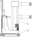
Fig. 1 is a front view of a handcart type circuit breaker in an embodiment 1 of a switchgear of the present invention;
fig. 2 is a left side view of a handcart type circuit breaker in embodiment 1 of the switchgear of the present invention;
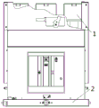
fig. 3 is a schematic structural diagram of a chassis of a handcart type circuit breaker in embodiment 1 of the switch cabinet of the invention when a vertical side plate of an operating mechanism is installed on the chassis;
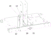
FIG. 4 is a partial schematic view at A of FIG. 3;
FIG. 5 is a schematic view of the crank arm of FIG. 4;
FIG. 6 is a schematic structural view of the push rod of FIG. 3;
fig. 7 is a schematic structural diagram of a first view angle when a vertical side plate of an operating mechanism is mounted on a chassis of a handcart type circuit breaker in embodiment 2 of the switch cabinet of the invention;
fig. 8 is a structural schematic diagram of a second view angle when a vertical side plate of an operating mechanism is mounted on a chassis of a handcart type circuit breaker in embodiment 2 of the switch cabinet of the invention;
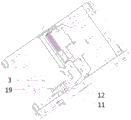
fig. 9 is a schematic structural diagram of a handcart type circuit breaker in embodiment 2 of the switch cabinet of the present invention when a circuit breaker bottom plate is displayed on a chassis;
in the drawings: 1-a circuit breaker; 2-chassis vehicle; 3-chassis underbody; 4-end beam; 5-vertical side plates; 6-rotating shaft; 7-crank arm, 71-long groove; 72-crank arm lock hole; 8-a support plate; 9-shaft sleeve; 10-rocker insertion opening; 11-push rod, 111-push rod perforation; 12-a guide plate; 13-opening half shaft; 14-opening brake bending plate; 15-a spring; 16-chassis keyhole; 17-a locking bar; 18-a locking plate; 19-a guide structure mounting plate; 20-breaker chassis.
Detailed Description
A specific embodiment of the switchgear of the present invention will now be described with reference to the accompanying drawings.
In embodiment 1 of the switch cabinet, the switch cabinet comprises a cabinet body and a handcart type circuit breaker which can advance and withdraw relative to the cabinet body, as shown in fig. 1-3, the handcart type circuit breaker in the switch cabinet comprises a chassis vehicle 2 and a circuit breaker 1 arranged on the chassis vehicle, the part of the circuit breaker 1 which is inserted into the cabinet body and exposed outside is the front side of the handcart type circuit breaker, the chassis vehicle 2 comprises a chassis vehicle bottom plate 3 and an end beam 4 arranged on the front side of the chassis vehicle bottom plate, the chassis vehicle bottom plate 3 is provided with the circuit breaker 1, the circuit breaker 1 is provided with a circuit breaker bottom plate, the circuit breaker bottom plate is arranged on the chassis vehicle bottom plate (the circuit breaker bottom plate is not shown), and a vertical side plate 5 of an operating mechanism of the circuit breaker is arranged. Handcart-type circuit breaker still includes urgent separating brake mechanism, urgent separating brake mechanism sets up the outside of the vertical curb plate 5 of operating mechanism of circuit breaker and is close to the front side of chassis car, urgent separating brake mechanism includes axis of rotation 6 and turning arm 7, as shown in fig. 4, the welding has two backup pads 8 on the chassis bottom plate 3 of 4 rear sides of end beam, the one end of turning arm 7 is installed between two backup pads 8, backup pad 8 and turning arm 7 are passed to 6 levels of axis of rotation, and rotate through axle sleeve 9 and install on end beam 4, axis of rotation 6 can drive turning arm 7 and rotate, and the one end of axis of rotation 6 has rocker inserted hole 10 and exposes from backup pad 8, in order to make things convenient for operating personnel to use the rotatory axis of rotation of rocker.
The emergency brake separating mechanism further comprises a pushing member, the pushing member is a pushing rod 11, as shown in fig. 5, a horizontally extending long groove 71 is arranged at the other end of the crank arm 7, a connecting pin is arranged at one end of the pushing rod 11, and the connecting pin is arranged in the long groove 71 in a penetrating mode to realize connection between the crank arm 7 and the pushing rod 11. In other embodiments, the elongated slot is disposed on the push rod, and the connecting pin is disposed at one end of the crank arm.
In order to realize the vertical linear motion of catch bar, urgent separating brake device still includes guide structure, guide structure installs on the vertical curb plate 5 of the operating mechanism of circuit breaker, guide structure includes two deflector 12 of interval installation on vertical curb plate 5 from top to bottom, be equipped with the guiding hole on deflector 12, catch bar 11 wears to adorn in the guiding hole of each deflector and vertical extension, when connecting lever 7 rotates, catch bar 11 can be driven by connecting lever 7 and follow the length direction straight line action of catch bar 12. In other embodiments, only one guide plate is arranged, and the thickness of the guide plate is larger, so that the push rod can be stably guided.
The opening half shaft 13 of the handcart type circuit breaker penetrates through a through hole of an opening half shaft on a vertical side plate 5 of an operating mechanism of the circuit breaker, the opening half shaft is arranged along the horizontal direction and is perpendicular to the push rod 11, an opening bent plate 14 which is radially suspended is arranged on the opening half shaft 13, and the push rod 11 can push the opening bent plate 14 and enable the opening half shaft 13 to rotate when moving linearly so as to enable the circuit breaker to be opened.
In order to ensure that the push rod 11 and the brake separating bent plate 14 have a certain distance in a non-emergency state so that normal switching on and off of the circuit breaker is not interfered and the push rod 11 can automatically reset after emergency brake separating, a spring 15 is arranged on the push rod 11 in a penetrating manner, the spring 15 is positioned between the two guide plates 12, as shown in fig. 6, push rod through holes 111 are arranged on the push rod 11 at intervals up and down, the lower end of the spring 15 is blocked by a blocking member arranged on the push rod through hole 111 in a penetrating manner, the blocking member is specifically a spring blocking pin, the upper end of the spring 15 tightly supports the guide plates 12, and the spring 15 can provide acting force for the push member 11 to move towards the resetting direction. In order to limit the limit position of the pushing rod 11 moving to the reset direction, a stop pin is installed on the part of the pushing rod 11 above the upper guide plate 12, the stop pin is inserted into the upper pushing rod through hole, when the pushing rod 11 is reset to the limit position under the action of the spring 15, the stop pin on the pushing rod 11 is stopped by the upper guide plate 12 to limit the pushing rod 11 to move continuously. In other embodiments, the stop member and the push rod are of an integral structure, and the stop member is a boss integrally arranged on the push rod.
In order to avoid the misoperation of non-professionals, the emergency brake-separating mechanism further comprises a mechanical lock structure, the mechanical lock structure comprises a crank arm lock hole 72, a chassis lock hole 16 positioned on the end beam, a lock rod 17 and a lock plate 18, the lock plate 18 is installed on the end beam 4 and is provided with a lock plate hole, and the lock rod 17 can be inserted into the crank arm lock hole 72 and the chassis lock hole to lock the emergency brake-separating mechanism. When the lock rod 17 is inserted into the crank arm lock hole 72, the emergency brake-separating mechanism is in a locking state; when the lock rod 17 is drawn out from the crank arm lock hole 72, the emergency opening mechanism is in an unlocking state, and the lock rod 17 can be placed in the square groove of the lock plate to prevent the lock rod from being lost.
When the electric brake-separating of the switch cabinet breaks down and needs emergency brake-separating, the rotating shaft 6 is manually rotated to enable the connecting lever 7 to rotate, the push rod 11 connected with the connecting lever 7 pushes the brake-separating bent plate 14 on the brake-separating half shaft 13 under the driving of the connecting lever 7 to enable the brake-separating half shaft 13 to rotate, and further the emergency brake-separating of the circuit breaker is achieved, the spring 15 in the reset mechanism can enable the push rod 11 and the brake-separating bent plate 14 to keep a set relative position in a non-emergency state when the push rod is not actively operated, the set relative position is not established between the push rod and the brake-separating bent plate 14, a transmission relation is not established between the push rod and the brake-separating bent plate, so that the normal brake-separating and closing of the circuit breaker are not interfered by the pushing piece, meanwhile, the pushing piece can automatically reset under the action of the reset mechanism after. The emergency brake-separating device can still perform emergency brake-separating operation when the electric brake-separating of the switch cabinet breaks down, and the reliability of the switch cabinet is improved.
The above is only a preferred embodiment of the present invention, and it should be noted that the above preferred embodiment should not be considered as limiting the present invention, and the protection scope of the present invention should be subject to the scope defined by the claims. The present invention may also take the following embodiments:
Example 7 of the switchgear of the invention: in embodiment 1, the mechanical lock structure includes a crank lock hole, a chassis lock hole located on the end beam, a lock lever and a lock plate, the lock plate is installed on the end beam and has a lock plate hole, the lock lever can be inserted into the crank lock hole and the chassis lock hole to lock the emergency opening mechanism, in embodiment 7, the mechanical lock structure includes an L-shaped lock lever having one end capable of fitting the rocker insertion hole of the rotating shaft in a detent manner and a lock plate having a notch, two detent columns symmetrically distributed along the axis of the end portion are provided on the peripheral surface of the end of the L-shaped lock lever fitting the rocker insertion hole in the detent manner, the two detent columns can be respectively inserted into the two detent grooves on the rocker insertion hole, the lock plate is fixed on the end beam, when the end of the L-shaped lock lever having the detent columns is inserted into the rocker insertion hole of the rotating shaft, the two detent columns are respectively inserted into the two detent grooves on the rocker insertion hole of the rocker insertion hole, the L-, the other end of the L-shaped lock rod is clamped into the opening of the lock plate, the L-shaped lock rod cannot rotate under the limitation of the opening, and then a rocker insertion opening of the rotating shaft which is in rotation-stopping fit with the L-shaped lock rod cannot rotate, namely, the rotating shaft is locked and cannot rotate, and the emergency brake-separating mechanism is in a locking state at the moment; when the L-shaped lock rod is pulled out from the rocker insertion opening, the rotation stopping matching relation between the rocker insertion opening of the rotating shaft and the L-shaped lock rod is released, the rotating shaft can rotate, and the emergency brake-separating mechanism is in an unlocking state at the moment.
In the embodiment of the handcart type circuit breaker, the structure of the handcart type circuit breaker is consistent with that of the handcart type circuit breaker in the switch cabinet of any embodiment, and the details are not repeated.
In the embodiment of the chassis truck of the present invention, embodiment 1 of the structure of the chassis truck is the same as the structure of the chassis truck in embodiment 2 of the switch cabinet, and details thereof are not repeated. The chassis can also adopt the following implementation modes:
example 2 of the chassis of the present invention: in the embodiment 1 of the chassis truck, the spring is arranged on the push rod in a penetrating mode and is a pressure spring, in the embodiment 2 of the chassis truck, the spring is a tension spring, one end of the tension spring is fixed to a chassis bottom plate, the other end of the tension spring is fixed to a rod body of the push rod, the tension spring is stretched when the push rod moves upwards, and after the opening is completed, the push rod resets under the action force of the tension spring.
Example 3 of the chassis of the present invention: in the chassis car of embodiment 1, the spring and the spring stopper pin are located between the two guide plates, and the stopper pin is located above the upper guide plate, and in the chassis car of embodiment 3, the spring and the spring stopper pin are located below the lower guide plate, and the stopper pin is located above the upper guide plate, or the spring and the spring stopper pin are located below the lower guide plate, and the stopper pin may also be located between the two guide plates.
Example 4 of the chassis of the present invention: in the embodiment 1 of chassis car, the deflector of upside both has the guide effect and has the effect of restriction catch bar extreme position, in the embodiment 4 of chassis car, install guide sleeve on the guide structure mounting panel, the catch bar passes from guide sleeve, lead to the catch bar by guide sleeve, install the limiting plate on the guide structure mounting panel, the tight limiting plate in upper end top of spring, the through-hole on the limiting plate is greater than the external diameter of catch bar, this limiting plate only plays the effect that the restriction catch bar resets extreme position.
Example 5 of the chassis of the present invention: in the embodiment 1 of the chassis truck, the mechanical lock structure includes a crank arm lock hole, a chassis lock hole located on the end beam, a lock bar and a lock plate, the lock plate is installed on the end beam and has a lock plate hole, the lock bar can be inserted into the crank arm lock hole and the chassis lock hole to lock the emergency opening mechanism, in the embodiment 5 of the chassis truck, the mechanical lock structure includes an L-shaped lock bar and a lock plate with a notch, one end of the L-shaped lock bar is locked and matched with the rocker insertion hole of the rotating shaft, two rotation-stopping columns symmetrically distributed along the axis of the end part are arranged on the peripheral surface of one end of the L-shaped lock bar, which is locked and matched with the rocker insertion hole of the rotating shaft, the two rotation-stopping columns can be respectively inserted into the two rotation-stopping grooves on the rocker insertion hole, the lock plate is fixed on the end beam, when one end of the L-shaped lock bar with the rotation-stopping column is inserted into the rocker insertion hole of the rotating shaft, the two rotation, the other end of the L-shaped lock rod is clamped into the opening of the lock plate, the L-shaped lock rod cannot rotate under the limitation of the opening, and then a rocker insertion opening of the rotating shaft which is in rotation-stopping fit with the L-shaped lock rod cannot rotate, namely, the rotating shaft is locked and cannot rotate, and the emergency brake-separating mechanism is in a locking state at the moment; when the L-shaped lock rod is pulled out from the rocker insertion opening, the rotation stopping matching relation between the rocker insertion opening of the rotating shaft and the L-shaped lock rod is released, the rotating shaft can rotate, and the emergency brake-separating mechanism is in an unlocking state at the moment.
Claims (10)
1. A chassis vehicle comprises a vehicle body and is characterized in that,
the emergency brake-separating mechanism is arranged on the vehicle body;
urgent separating brake mechanism includes:
the rotating shaft is rotatably arranged on the chassis vehicle, one end of the rotating shaft is exposed out of the front side of the chassis vehicle, and the rotating shaft is provided with a crank arm;
the guide structure is arranged on the vehicle body;
the pushing piece is arranged in the guide structure in a guiding mode and extends vertically;
one of the pushing piece and the crank arm is provided with a horizontally extending long groove, the other one of the pushing piece and the crank arm is provided with a connecting pin, and the connecting pin is arranged in the long groove in a penetrating mode to realize connection of the pushing piece and the crank arm so as to drive the pushing piece to linearly act in the vertical direction when the crank arm rotates and drive the opening half shaft to rotate for opening;
the reset mechanism comprises a spring for providing acting force for the pushing piece to move towards the reset direction, and a limiting structure for limiting the limit position of the pushing piece when the pushing piece moves towards the reset direction.
2. The chassis vehicle according to claim 1, wherein: the guide structure comprises a guide plate, a guide hole is formed in the guide plate, the pushing piece is arranged in the guide hole of the guide plate in a penetrating mode, a stopping piece is arranged on or integrally connected with the pushing piece, the spring is arranged on the pushing piece in a penetrating mode, one end of the spring is stopped by the stopping piece, the other end of the spring abuts against the guide plate, the limiting structure is a stopping pin arranged on the pushing piece, and the stopping pin is located above the guide plate and is stopped with the guide plate when the pushing piece resets to limit the limiting position of the pushing piece.
3. The chassis vehicle according to claim 2, wherein: the guide plates are arranged at intervals from top to bottom, the spring is arranged between the two guide plates, and the stop pin is positioned above the guide plate on the upper side.
4. The chassis vehicle according to claim 1, wherein: the chassis truck is provided with a limiting plate, the pushing piece vertically penetrates through the limiting plate, the pushing piece is provided with or integrally connected with a stopping piece, the spring is arranged on the pushing piece in a penetrating mode, one end of the spring is stopped by the stopping piece, the other end of the spring abuts against the limiting plate, the limiting structure is a stop pin arranged on the pushing piece, and the stop pin is located above the limiting plate and is stopped with the limiting plate when the pushing piece resets so as to limit the limiting position of the pushing piece.
5. The chassis vehicle according to any one of claims 1 to 4, wherein: the emergency brake-separating mechanism also comprises a mechanical lock structure for locking the pushing piece at the limit position.
6. The chassis vehicle according to claim 5, wherein: the mechanical lock structure comprises a crank arm lock hole in the crank arm, a chassis lock hole in the chassis car and a lock rod, and the lock rod can be inserted into the crank arm lock hole and the chassis lock hole to lock the emergency brake-separating mechanism.
7. A handcart type circuit breaker comprises a chassis and a circuit breaker arranged on the chassis,
it is characterized in that the utility model is characterized in that,
handcart-type circuit breaker still includes urgent separating brake mechanism, and urgent separating brake mechanism includes:
the rotating shaft is rotatably arranged on the chassis vehicle, one end of the rotating shaft is exposed out of the front side of the chassis vehicle, and the rotating shaft is provided with a crank arm;
the pushing piece is limited on the chassis vehicle through the guide structure and extends vertically, and the pushing piece is perpendicular to the opening half shaft of the circuit breaker;
one of the pushing piece and the crank arm is provided with a horizontally extending long groove, the other one of the pushing piece and the crank arm is provided with a connecting pin, and the connecting pin is arranged in the long groove in a penetrating mode to realize connection of the pushing piece and the crank arm so as to drive the pushing piece to linearly act in the vertical direction when the crank arm rotates, and drive the opening half shaft to rotate to open when the pushing piece linearly acts;
the reset mechanism comprises a spring for providing acting force for the pushing piece to move towards the reset direction, and a limiting structure for limiting the limit position of the pushing piece when the pushing piece moves towards the reset direction.
8. The handcart type circuit breaker of claim 7, wherein: the guide structure is installed on a vertical side plate of an operating mechanism of the circuit breaker.
9. The handcart type circuit breaker of claim 8, wherein: the guide structure comprises a guide plate, a guide hole is formed in the guide plate, the pushing piece is arranged in the guide hole of the guide plate in a penetrating mode, a stopping piece is arranged on or integrally connected with the pushing piece, the spring is arranged on the pushing piece in a penetrating mode, one end of the spring is stopped by the stopping piece, the other end of the spring abuts against the guide plate, the limiting structure is a stopping pin arranged on the pushing piece, and the stopping pin is located above the guide plate and is stopped with the guide plate to limit the limiting position of the pushing piece when the pushing piece resets.
10. A kind of switch cabinet, its characterized in that: including the cabinet body and the handcart-type circuit breaker that can advance and pull out relatively the cabinet body, handcart-type circuit breaker includes the chassis car and installs the circuit breaker on the chassis car, and handcart-type circuit breaker still includes urgent separating brake mechanism, and urgent separating brake mechanism includes:
the rotating shaft is rotatably arranged on the chassis vehicle, one end of the rotating shaft is exposed out of the front side of the chassis vehicle, and the rotating shaft is provided with a crank arm;
the pushing piece is limited on the chassis vehicle through the guide structure and extends vertically, and the pushing piece is perpendicular to the opening half shaft of the circuit breaker;
one of the pushing piece and the crank arm is provided with a horizontally extending long groove, the other one of the pushing piece and the crank arm is provided with a connecting pin, and the connecting pin is arranged in the long groove in a penetrating mode to realize connection of the pushing piece and the crank arm so as to drive the pushing piece to linearly act in the vertical direction when the crank arm rotates, and drive the opening half shaft to rotate to open when the pushing piece linearly acts;
the reset mechanism comprises a spring for providing acting force for the pushing piece to move towards the reset direction, and a limiting structure for limiting the limit position of the pushing piece when the pushing piece moves towards the reset direction.
Priority Applications (1)
| Application Number | Priority Date | Filing Date | Title |
|---|---|---|---|
| CN201910936652.9A CN112582931A (en) | 2019-09-29 | 2019-09-29 | Chassis car, handcart-type circuit breaker and cubical switchboard |
Applications Claiming Priority (1)
| Application Number | Priority Date | Filing Date | Title |
|---|---|---|---|
| CN201910936652.9A CN112582931A (en) | 2019-09-29 | 2019-09-29 | Chassis car, handcart-type circuit breaker and cubical switchboard |
Publications (1)
| Publication Number | Publication Date |
|---|---|
| CN112582931A true CN112582931A (en) | 2021-03-30 |
Family
ID=75110838
Family Applications (1)
| Application Number | Title | Priority Date | Filing Date |
|---|---|---|---|
| CN201910936652.9A Pending CN112582931A (en) | 2019-09-29 | 2019-09-29 | Chassis car, handcart-type circuit breaker and cubical switchboard |
Country Status (1)
| Country | Link |
|---|---|
| CN (1) | CN112582931A (en) |
Citations (13)
| Publication number | Priority date | Publication date | Assignee | Title |
|---|---|---|---|---|
| JPH10126912A (en) * | 1996-10-24 | 1998-05-15 | Toshiba Corp | Taking-in and-out device for vacuum breaker |
| ES2207563T3 (en) * | 1999-09-30 | 2004-06-01 | Siemens Aktiengesellschaft | DRIVING FOR A POLAR MODULE OF A Circuit Breaker. |
| CN201584653U (en) * | 2009-11-20 | 2010-09-15 | 大全集团有限公司 | Switch cabinet electrified locking device |
| CN203351524U (en) * | 2013-07-05 | 2013-12-18 | 河南森源电气股份有限公司 | Breaker emergency opening device |
| CN203445024U (en) * | 2013-08-09 | 2014-02-19 | 西门子(上海)电气传动设备有限公司 | Locking device of earthing switch and earthing switch comprising same |
| CN203690152U (en) * | 2013-12-26 | 2014-07-02 | 常熟开关制造有限公司(原常熟开关厂) | Breaker |
| CN203983080U (en) * | 2014-07-08 | 2014-12-03 | 陕西中电高压电力开关有限公司 | Mechanical interlocking device for circuit breaker |
| CN204651269U (en) * | 2015-06-05 | 2015-09-16 | 常熟开关制造有限公司(原常熟开关厂) | Circuit breaker |
| CN205943818U (en) * | 2016-08-12 | 2017-02-08 | 泸州宏兴电气有限公司 | Prevent mistake and touch urgent minute brake gear |
| CN206210648U (en) * | 2016-09-27 | 2017-05-31 | 宁波燎原电器集团股份有限公司 | Breaker |
| CN206271581U (en) * | 2016-12-26 | 2017-06-20 | 山东泰开真空开关有限公司 | A kind of brake separating mechanism cabinet emergency opening and hanging locking device |
| CN207558649U (en) * | 2017-10-23 | 2018-06-29 | 深圳市惠程电气股份有限公司 | A kind of blocking device |
| CN208077831U (en) * | 2018-05-04 | 2018-11-09 | 常熟开关制造有限公司(原常熟开关厂) | A kind of breaker |
-
2019
- 2019-09-29 CN CN201910936652.9A patent/CN112582931A/en active Pending
Patent Citations (13)
| Publication number | Priority date | Publication date | Assignee | Title |
|---|---|---|---|---|
| JPH10126912A (en) * | 1996-10-24 | 1998-05-15 | Toshiba Corp | Taking-in and-out device for vacuum breaker |
| ES2207563T3 (en) * | 1999-09-30 | 2004-06-01 | Siemens Aktiengesellschaft | DRIVING FOR A POLAR MODULE OF A Circuit Breaker. |
| CN201584653U (en) * | 2009-11-20 | 2010-09-15 | 大全集团有限公司 | Switch cabinet electrified locking device |
| CN203351524U (en) * | 2013-07-05 | 2013-12-18 | 河南森源电气股份有限公司 | Breaker emergency opening device |
| CN203445024U (en) * | 2013-08-09 | 2014-02-19 | 西门子(上海)电气传动设备有限公司 | Locking device of earthing switch and earthing switch comprising same |
| CN203690152U (en) * | 2013-12-26 | 2014-07-02 | 常熟开关制造有限公司(原常熟开关厂) | Breaker |
| CN203983080U (en) * | 2014-07-08 | 2014-12-03 | 陕西中电高压电力开关有限公司 | Mechanical interlocking device for circuit breaker |
| CN204651269U (en) * | 2015-06-05 | 2015-09-16 | 常熟开关制造有限公司(原常熟开关厂) | Circuit breaker |
| CN205943818U (en) * | 2016-08-12 | 2017-02-08 | 泸州宏兴电气有限公司 | Prevent mistake and touch urgent minute brake gear |
| CN206210648U (en) * | 2016-09-27 | 2017-05-31 | 宁波燎原电器集团股份有限公司 | Breaker |
| CN206271581U (en) * | 2016-12-26 | 2017-06-20 | 山东泰开真空开关有限公司 | A kind of brake separating mechanism cabinet emergency opening and hanging locking device |
| CN207558649U (en) * | 2017-10-23 | 2018-06-29 | 深圳市惠程电气股份有限公司 | A kind of blocking device |
| CN208077831U (en) * | 2018-05-04 | 2018-11-09 | 常熟开关制造有限公司(原常熟开关厂) | A kind of breaker |
Similar Documents
| Publication | Publication Date | Title |
|---|---|---|
| CN101834412B (en) | Switch cabinet mechanical interlocking matched set | |
| ES2729032T3 (en) | Air Circuit Breaker Distribution Panel Door Locking Device | |
| CN205177689U (en) | Three -station isolation switch's operating mechanism | |
| JP2002369321A (en) | Lock of draw out type electric apparatus unit | |
| CN112582931A (en) | Chassis car, handcart-type circuit breaker and cubical switchboard | |
| CN201946903U (en) | Self-locking device for valve of removing type metal-enclosed switchgear | |
| CN211828535U (en) | Low-voltage cabinet door mechanical interlocking device | |
| CN203351524U (en) | Breaker emergency opening device | |
| CN105244217A (en) | Operating mechanism of three-station isolating switch | |
| KR101922156B1 (en) | Ground switch for distributing board | |
| CN112366103B (en) | Lower door interlocking device of switch cabinet | |
| CN104810199A (en) | Switching-on locking and unlocking device of circuit breaker and switching-on locking and unlocking method of switching-on locking and unlocking device | |
| TW200816249A (en) | Earthed breaker | |
| CN205428839U (en) | Body structure of circuit breaker | |
| CN210744594U (en) | Low-voltage drawer type switch cabinet | |
| CN201383464Y (en) | Mechanical locking misoperation prevention interlocking device | |
| CN107887199B (en) | Switch cabinet door-closing interlocking mechanism | |
| CN111200254B (en) | Switch cabinet and secondary interlocking device thereof | |
| CN213124286U (en) | Oil tank pressure relay protection device of oil-immersed transformer | |
| CN201332050Y (en) | Locking electromagnet module of high-voltage vacuum circuit breaker | |
| CN219711257U (en) | Quick unlocking device for high-voltage cabinet door | |
| CN216288258U (en) | Circuit breaker | |
| CN217589917U (en) | Fire control is with explosion-proof type dual supply block terminal | |
| CN220651856U (en) | Brake separating mechanism and distribution box | |
| CN220400511U (en) | Interlocking mechanism of high-voltage circuit breaker |
Legal Events
| Date | Code | Title | Description |
|---|---|---|---|
| PB01 | Publication | ||
| PB01 | Publication | ||
| SE01 | Entry into force of request for substantive examination | ||
| SE01 | Entry into force of request for substantive examination | ||
| RJ01 | Rejection of invention patent application after publication | ||
| RJ01 | Rejection of invention patent application after publication |
Application publication date: 20210330 |