CN112578199A - Integrated electrical testing device - Google Patents
Integrated electrical testing device Download PDFInfo
- Publication number
- CN112578199A CN112578199A CN202011295968.3A CN202011295968A CN112578199A CN 112578199 A CN112578199 A CN 112578199A CN 202011295968 A CN202011295968 A CN 202011295968A CN 112578199 A CN112578199 A CN 112578199A
- Authority
- CN
- China
- Prior art keywords
- wire
- voltage
- test
- platform
- wiring
- Prior art date
- Legal status (The legal status is an assumption and is not a legal conclusion. Google has not performed a legal analysis and makes no representation as to the accuracy of the status listed.)
- Pending
Links
- 238000012360 testing method Methods 0.000 title claims abstract description 183
- 238000012546 transfer Methods 0.000 claims abstract description 41
- 230000007246 mechanism Effects 0.000 claims abstract description 18
- 238000004804 winding Methods 0.000 claims abstract description 4
- 238000000034 method Methods 0.000 claims description 13
- 230000008569 process Effects 0.000 claims description 11
- 238000001514 detection method Methods 0.000 claims description 9
- 238000010146 3D printing Methods 0.000 claims description 4
- 238000005096 rolling process Methods 0.000 claims description 4
- 238000004891 communication Methods 0.000 claims description 3
- 230000000630 rising effect Effects 0.000 claims description 3
- 230000006872 improvement Effects 0.000 abstract description 2
- 238000010586 diagram Methods 0.000 description 8
- 230000008859 change Effects 0.000 description 3
- 238000012423 maintenance Methods 0.000 description 3
- 230000002159 abnormal effect Effects 0.000 description 2
- 230000001174 ascending effect Effects 0.000 description 2
- 230000010354 integration Effects 0.000 description 2
- WABPQHHGFIMREM-UHFFFAOYSA-N lead(0) Chemical compound [Pb] WABPQHHGFIMREM-UHFFFAOYSA-N 0.000 description 2
- 239000004575 stone Substances 0.000 description 2
- 208000027418 Wounds and injury Diseases 0.000 description 1
- 230000009286 beneficial effect Effects 0.000 description 1
- 230000005540 biological transmission Effects 0.000 description 1
- 230000009194 climbing Effects 0.000 description 1
- 230000006378 damage Effects 0.000 description 1
- 230000007547 defect Effects 0.000 description 1
- 238000013461 design Methods 0.000 description 1
- 238000003745 diagnosis Methods 0.000 description 1
- 238000007599 discharging Methods 0.000 description 1
- 230000000694 effects Effects 0.000 description 1
- 230000005611 electricity Effects 0.000 description 1
- 238000011156 evaluation Methods 0.000 description 1
- 208000014674 injury Diseases 0.000 description 1
- 238000009434 installation Methods 0.000 description 1
- 238000010234 longitudinal analysis Methods 0.000 description 1
- 238000012986 modification Methods 0.000 description 1
- 230000004048 modification Effects 0.000 description 1
- 238000007639 printing Methods 0.000 description 1
- 238000006467 substitution reaction Methods 0.000 description 1
- 239000000725 suspension Substances 0.000 description 1
Images


Classifications
-
- G—PHYSICS
- G01—MEASURING; TESTING
- G01R—MEASURING ELECTRIC VARIABLES; MEASURING MAGNETIC VARIABLES
- G01R31/00—Arrangements for testing electric properties; Arrangements for locating electric faults; Arrangements for electrical testing characterised by what is being tested not provided for elsewhere
-
- G—PHYSICS
- G01—MEASURING; TESTING
- G01R—MEASURING ELECTRIC VARIABLES; MEASURING MAGNETIC VARIABLES
- G01R1/00—Details of instruments or arrangements of the types included in groups G01R5/00 - G01R13/00 and G01R31/00
- G01R1/02—General constructional details
- G01R1/04—Housings; Supporting members; Arrangements of terminals
Abstract
The invention discloses an integrated electrical test device, belonging to the technical field of integrated electrical test devices; the technical problem to be solved is as follows: the improvement of the hardware structure of the integrated electrical test device is provided; the technical scheme for solving the technical problems is as follows: the testing device comprises a transfer box and a take-up and pay-off platform, wherein the transfer box comprises a box body and a cover body used for covering and the box body, two side surfaces of the box body are provided with a high-voltage wire inlet port and a low-voltage wire inlet port which are isolated from each other, and a testing loop used for switching testing items or other testing loops is arranged in the box body; the wire winding and unwinding platform comprises a wire box, a foldable lifting support is arranged in the wire box, a wire hanging platform is arranged at the top end of the foldable lifting support, and a wire clamping mechanism is arranged on the wire hanging platform; one end of the high-voltage wire inlet port and one end of the low-voltage wire inlet port connecting cable are connected with the adapter box, and the other end of the cable is placed on the wire take-up and pay-off platform through the wire clamping mechanism; the invention is applied to electrical tests.
Description
Technical Field
The invention discloses an integrated electrical testing device, and belongs to the technical field of integrated electrical testing devices.
Background
The acceptance, diagnosis, routine electrical tests and the like of the power equipment in the installation, debugging and operation processes become an important means for guaranteeing the safe operation of the power grid. The electrical test of the power equipment refers to various tests performed for mastering the electrical performance and the operating condition of the power equipment, and state evaluation is made through transverse and longitudinal analysis and comparison according to test data, so that scientific basis is provided for better operation and maintenance of the power equipment.
At present, the main method for wiring in domestic and foreign tests is as follows: the manual ascending pulls the wiring through the rope, and the wiring needs to be replaced once each test step is completed.
The test items of the power equipment are various and different, different test wiring is carried out on the tested equipment according to the test items, the sequence, the method and the precision, particularly, the test wiring mode needs to be frequently changed when large-scale equipment is tested, the phenomena of wrong connection, missed connection, poor wiring and the like are easy to occur, and time and labor are wasted. In the electrical test process of a large transformer, after test lines are connected according to the rule requirements, personnel withdraw from a main transformer body, but frequent replacement of the connection lines requires that the personnel stay on the main transformer for a long time to work, and danger is easy to occur. Frequent wiring replacement in high-altitude operation easily leads to wiring errors, so that the test duration is increased slightly, and the equipment is damaged seriously to cause personnel injury. Frequent replacement of test wiring requires up-down transmission, climbing height is low, working efficiency is low, and large potential safety hazards exist in the high-altitude operation process.
The traditional test wiring mode exposes the problems of safety, reliability, poor data stability, low working efficiency and the like, and can not meet the requirements of power equipment test work. Therefore, it is necessary to provide an integrated electrical test switching complete device which can perform wiring once, is simple in operation, safe and reliable, can perform wiring up and down conveniently and quickly, and can realize integration of different test items in one switching box.
Disclosure of Invention
In order to overcome the defects in the prior art, the invention aims to solve the technical problems that: an improvement of a hardware structure of an integrated electrical test apparatus is provided.
In order to solve the technical problems, the invention adopts the technical scheme that: the integrated electrical test device comprises a transfer box and a take-up and pay-off platform, wherein the transfer box comprises a box body and a cover body for covering and covering the box body, two side surfaces of the box body are provided with a high-voltage wire inlet port and a low-voltage wire inlet port which are isolated from each other, the box body is provided with an operation panel for testing a wire transfer end, and the box body is internally provided with a test loop for switching test items or other test loops;
the wire winding and unwinding platform comprises a wire box, a foldable lifting support is arranged in the wire box, a wire hanging platform is arranged at the top end of the foldable lifting support, and a wire clamping mechanism is arranged on the wire hanging platform;
the high-voltage wire inlet port and the low-voltage wire inlet port are connected with one end of a cable and are connected with the transfer box, the other end of the cable is placed on the wire take-up and pay-off platform through the wire clamping mechanism, the wire take-up and pay-off platform is fixed with equipment through a hanging chain after rising to a specified height, and the other end of the cable is connected to the equipment in a telescopic mode through the wire clamping mechanism.
The test loop comprises a detection loop capable of switching Alternating Current (AC) 220V to Direct Current (DC) 5V, and the switching of the detection loop is realized by the mutual matching of a switch and an indicator lamp which are arranged on the operation panel and are used for testing the wiring switching end at low voltage.
The operation panel is provided with a high-voltage test wiring transfer end and a medium-voltage test wiring transfer end, and the high-voltage test wiring transfer end and the medium-voltage test wiring transfer end are provided with test line plugs, test lamps, a change-over switch and a D printing sleeve;
and the high-voltage test wiring switching end and the medium-voltage test wiring switching end are respectively provided with a high-voltage end screen wiring switching end and a medium-voltage end screen wiring switching end.
The high-voltage end screen wiring switching end comprises a high-voltage end screen outgoing terminal and a high-voltage end screen non-grounding switch, and the medium-voltage end screen wiring switching end comprises a medium-voltage end screen outgoing terminal and a medium-voltage end screen non-grounding switch.
And the operating panel is also provided with a power interface and a test switch.
The bottom of line case is still through the folding support base of bolt fixedly connected with, the folding support base includes a plurality of supporting wheels and a plurality of landing leg, the four corners at the folding support base is fixed to the supporting wheel, the one end of landing leg is passed through axis of rotation and folding support base swing joint, the other end of landing leg and the one end swing joint of supporting legs, the supporting legs passes through swing joint rod folding connection at the landing leg end.
The foldable lifting support is specifically arranged as a scissor-type lifting support, at least two electric push rods are arranged on the foldable lifting support, each electric push rod comprises a controller, and the controllers are connected with the rechargeable batteries through wires.
The wire take-up and pay-off platform is further provided with a remote controller, the remote controller is connected with the controller through the wireless communication module, and the electric push rod is remotely controlled to complete lifting and withdrawing of the foldable lifting support.
The wire hanging platform comprises a tray, the wire clamping mechanism comprises a wire clamping rod and a binding coil, a sliding groove is formed in the bottom of the tray, the tray is fixedly connected with one end of an X-folding frame at the top end of the foldable lifting support, and the other end of the X-folding frame is connected with the sliding groove in a sliding mode;
the wire clamping rods are arranged at two ends of the inner side of the tray, and the beam coil is provided with a plurality of wire clamping rods which are respectively arranged at the front side of the tray.
And the platform folding angle of the wire hanging platform is provided with an arc rolling wheel used for preventing the test wire from being damaged in the drawing process.
Compared with the prior art, the invention has the beneficial effects that: the integrated electrical experimental device provided by the invention integrates the conventional transformer test items into one transfer box by simply switching the test loops through the transfer box of the integrated switching test items or other test loops through the switch, and the test is completed without frequently replacing the wiring at high altitude by wiring personnel, thereby ensuring the safety of the wiring personnel and quickly completing the test work; the electric liftable coiling and uncoiling platform is provided with the angle-adjustable folding supporting base, the stable supporting of the bottom surface with stones is convenient to lay, the scissor type support can be quickly and stably lifted, the wire hanging platform is lifted to the wiring position of equipment and then is fixed with the equipment by using the hanging chain, the problem of coiling and uncoiling at high altitude in the test process is effectively solved, the platform can be used for transmitting some tools and equipment parts up and down, the overall efficiency of field maintenance and test work is greatly improved, and the unsafe behavior of throwing articles up and down in high altitude operation is avoided.
Drawings
The invention is further described below with reference to the accompanying drawings:
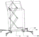
FIG. 1 is a schematic structural view of the present invention;
FIG. 2 is a schematic structural view of an operation panel on the transfer box according to the present invention;
FIG. 3 is a schematic structural view of a folding support base at the bottom of the wire box according to the present invention;
FIG. 4 is a schematic structural view of a foldable lifting bracket of the present invention;
FIG. 5 is a schematic structural diagram of the wire hanging platform of the present invention;
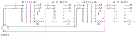
FIG. 6 is a schematic diagram of the high voltage test loop wiring inside the transfer box of the present invention;
FIG. 7 is a schematic diagram of the medium voltage test loop wiring inside the transfer box of the present invention;
FIG. 8 is a schematic diagram of the low voltage test loop wiring inside the transfer box of the present invention;
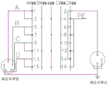
FIG. 9 is a schematic diagram of the high voltage end screen test loop wiring inside the transfer box of the present invention;
FIG. 10 is a schematic diagram of the medium voltage end screen test loop wiring within the transfer box of the present invention;
FIG. 11 is a schematic circuit diagram of the detection loop of the present invention;
FIG. 12 is a wiring diagram of the test circuit for converting 220V AC to 5V AC according to the present invention.
In the figure: the device comprises a switching box 1, a take-up and pay-off platform 2, a box body 11, a high-voltage wire inlet port 12, a low-voltage wire inlet port 13, an operation panel 14, a wire box 21, a foldable lifting support 22, a wire hanging platform 23, a wire clamping mechanism 24, a high-voltage test wire connecting end 141, a medium-voltage test wire connecting end 142, a low-voltage test wire connecting end 143, a test wire plug 144, a test lamp 145, a change-over switch 146, a 3D printing sleeve 147, a power interface 148, a test switch 149, a folding supporting base 211, a tray 231, a sliding groove 232, a wire clamping rod 241 and a beam coil 242, wherein the switching box 21 is a wire box, the foldable lifting support 22 is a foldable lifting support, the power interface 148 is a power interface, the test;
1411 is a high-voltage end screen wiring transfer end, 1421 is a medium-voltage end screen wiring transfer end, 1431 is a selector switch, 1432 is an indicator light, 2101 is a support wheel, 2102 is a support leg, 2103 is a support leg, 2104 is a movable connecting rod, and 2201 is an electric push rod.
Detailed Description
As shown in fig. 1 to 12, the integrated electrical testing device of the present invention includes an adaptor box 1 and a take-up and pay-off platform 2, wherein the adaptor box 1 includes a box body 11 and a cover body for covering and covering the box body, two side surfaces of the box body 11 are provided with a high voltage wire inlet port 12 and a low voltage wire inlet port 13 which are isolated from each other, the box body 11 is provided with an operation panel 14 for testing a wire connection adaptor end, and the box body 11 is provided with a test loop for switching test items or others;
the wire winding and unwinding platform 2 comprises a wire box 21, a foldable lifting support 22 is arranged inside the wire box 21, a wire hanging platform 23 is arranged at the top end of the foldable lifting support 22, and a wire clamping mechanism 24 is arranged on the wire hanging platform 23;
the high-voltage wire inlet port 12 and the low-voltage wire inlet port 13 are connected with one end of a cable and are connected with the transfer box 1, the other end of the cable is placed on the wire take-up and pay-off platform 2 through the wire clamping mechanism 24, the wire take-up and pay-off platform 2 is fixed with equipment through a hanging chain after rising to a specified height, and the other end of the cable is connected to the equipment in a telescopic mode through the wire clamping mechanism 24.
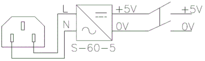
The test circuit comprises a detection circuit which can realize the switching from alternating current 220V to direct current 5V, and the switching of the detection circuit is realized by the mutual matching of a switch 1431 and an indicator lamp 1432 which are arranged on the operation panel 14 and are used for low-voltage test wiring switching-over terminals 143.
The operation panel 14 is provided with a high-voltage test wiring connection end 141 and a medium-voltage test wiring connection end 142, and the high-voltage test wiring connection end 141 and the medium-voltage test wiring connection end 142 are both provided with a test line plug 144, a test lamp 145, a change-over switch 146 and a 3D printing sleeve 147;
the high-voltage test connection switching end 141 and the medium-voltage test connection switching end 142 are further respectively provided with a high-voltage end screen connection switching end 1411 and a medium-voltage end screen connection switching end 1421.
The high-voltage end screen connection switching terminal 1411 includes a high-voltage end screen outgoing terminal and a high-voltage end screen non-grounding switch, and the medium-voltage end screen connection switching terminal 1421 includes a medium-voltage end screen outgoing terminal and a medium-voltage end screen non-grounding switch.
The operation panel 14 is also provided with a power interface 148 and a test switch 149.
The bottom of the wire box 21 is further fixedly connected with a folding supporting base 211 through bolts, the folding supporting base 211 comprises a plurality of supporting wheels 2101 and a plurality of supporting legs 2102, the supporting wheels 2101 are fixed at four corners of the folding supporting base 211, one ends of the supporting legs 2102 are movably connected with the folding supporting base 211 through rotating shafts, the other ends of the supporting legs 2102 are movably connected with one ends of supporting legs 2103, and the supporting legs 2103 are connected to the tail ends of the supporting legs 2101 through movable connecting rods 2104 in a foldable mode.
The foldable lifting support 22 is specifically configured as a scissor-type lifting support, at least two electric push rods 2201 are arranged on the foldable lifting support 22, each electric push rod 2201 comprises a controller, and the controller is connected with the rechargeable battery through a wire.
The wire take-up and pay-off platform 2 is further provided with a remote controller, and the remote controller is connected with the controller through a wireless communication module to realize remote control of the electric push rod 2201 to complete lifting and retracting of the foldable lifting support 22.
The wire hanging platform 23 comprises a tray 231, the wire clamping mechanism 24 comprises a wire clamping rod 241 and a binding coil 242, a sliding groove 232 is formed in the bottom of the tray 231, the tray 231 is fixedly connected with one end of an X-folding frame at the top end of the foldable lifting support 22, and the other end of the X-folding frame is connected with the sliding groove 232 in a sliding mode;
the wire clamping bars 241 are disposed at both ends of the inner side of the tray 231, and the plurality of the bundle coils 242 are disposed at the front side of the tray 231, respectively.
And arc rolling wheels used for preventing the test wire from being damaged in the drawing process are arranged at the platform folding corners of the wire hanging platform 23.
The integrated electrical test device provided by the invention mainly comprises an adapter box 1 and an electric lifting wire take-up and pay-off platform 2. The adapter box 1 adopts a three-dimensional design, the high, medium and low sleeves are distinguished and connected, the left side is a low-voltage wire inlet port 13, the front side is a high-voltage wire inlet port 12, and high and low voltages are mutually isolated and insulated, so that the requirement of test safety is met. The operation panel 14 is a testing wiring switching end and is composed of a 3D printing sleeve 147, a testing wire plug 144, a switching-on testing lamp 145, a change-over switch 146 and the like, the wiring area of the high, medium and low voltage sleeves is divided, the whole is attractive, and the wiring is convenient, rapid, safe and reliable.
The transfer box 1 has the function of quickly testing whether the wiring is good or not, is provided with a multifunctional logic control circuit, and changes the traditional wiring mode of one wire and one connector. Whether the wire clamping mechanism of the worker is clamped or not can be quickly confirmed by the safe voltage direct current 5V indicating lamp, and the problems that a loop is not communicated, the clamp discharges electricity and the wire connection is repeatedly carried out after the safe discharge of the test is stopped are solved. Through the switching of change over switch 146, change experimental wiring, fuse six electric test project wiring in a device for the test process is safe high-efficient, reduces personnel and the equipment under test direct contact number of times, avoids frequently ascending a height the operation, reduces repeated wiring, receipts line, avoids phenomenons such as mistake grafting, misconnection.
The transfer box 1 of the invention transfers the high-altitude wiring and line changing work to the ground for simple switching, realizes test wiring integration, effectively improves the personal safety protection level and reduces the accident occurrence probability.
The electric lifting wire take-up and pay-off platform 2 comprises a folding supporting base 211, a scissor-type foldable lifting support 22, a wire hanging platform 23 and a wire box 21 for storing and paying off wires. Through adjustable angle's folding support base 211, the quick steady lift of scissors formula support, it is fixed with equipment that the chaining uses behind the hanging wire platform 23 risees to equipment wiring position, and the highest liftable is 5.2 meters. The test wire clamping mechanism is fixed at the top of the support, the wire clamping mechanism can be pulled and used after being lifted to a proper position, and the arc rolling wheels at the folding corners of the platform ensure that the test wire is not damaged in the pulling process. The wire take-up and pay-off platform 2 can be operated remotely, a 12V direct current push rod is driven by a rechargeable battery to lift, and the auxiliary test wiring work is efficiently completed.
The support wheels 2101 of the invention can be specifically arranged as universal wheels, which is convenient for the dragging of the cable box 21 on the road surface, saves labor and is convenient, the arrangement of the folding support base 211 can stably place the cable box 21 on the stone road at the wiring position of the transformer, the support legs 2102 of the folding support base 211 realize the angle adjustment of the support legs 2102 in the horizontal direction through the rotating shafts, and the support legs 2103 realize the folding and unfolding support on the support legs 2102 through the movable connecting rods 2104 after the folding support base is used and is folded into the base.
The pay-off and take-up platform 2 not only effectively solves the problem of pay-off and take-up in the high altitude in the test process, but also can utilize the platform to transmit some tools and equipment parts up and down, thereby greatly improving the overall efficiency of on-site maintenance and test work, and simultaneously avoiding the unsafe behavior of throwing articles up and down in the high altitude operation.
When the test device is used, the wiring of the tested equipment is connected with all the wires, the connector on the operation panel 14 of the transfer box 1 is connected with the connector on the corresponding test testing equipment through the conducting wire at the testing platform on the ground, the test items or the different test loops can be switched through the test transfer wire loop, the test loops are simply switched through the change-over switch 146, all the tests of the conventional test items of the transformer can be completed, the wiring personnel does not need to frequently change the wiring at high altitude, the safety of the wiring personnel is ensured, and the test work can be quickly completed; meanwhile, a worker quickly and safely raises the cable to the height of the transformer through the take-up and pay-off platform 2 by using one end of the wiring terminal through the high-voltage wire inlet port 12 and the low-voltage wire inlet port 13, and the worker conducts different test projects of different phases by operating different change-over switches 146 after the cable is connected.
The detection loop is arranged in the transfer box, whether the test wiring loop is good or not can be quickly detected, and the problems that the conventional test wiring is not through and is difficult to prejudge are solved. The traditional operation mode is that workers ascend to operate and wire on a transformer sleeve, the workers leave the tested equipment after the wiring is completed, the operating personnel of the testing instrument starts up to test, the conditions of discharging, abnormal instrument test, abnormal test data and the like are found in the test process, the workers also ascend to operate and re-wire the test and judge whether the reason is the reason of poor wiring, and a large amount of time and labor cost are wasted. According to the invention, a switchable test circuit for converting alternating current 220V into direct current 5V is added in the test wiring circuit, as shown in fig. 12, a change-over switch 1531 and an indicator lamp 1432 are matched with each other, so that a wiring worker can perform direct current 5V low-voltage test when performing real-time wiring, the safety of the wiring worker is ensured, the condition that the low voltage cannot puncture a virtual connection part during virtual wiring is also ensured, and the condition that whether the test wiring is good can be accurately judged by checking whether the indicator lamp is turned on after the test worker switches over the switch, so that the virtual connection is prevented from influencing the test work.
The change-over switch 146 and the change-over switch 1431 on the operation panel 14 of the invention are provided with 3 modes, namely three modes of grounding, test and suspending, and during the test, different modes are adjusted by operating the rotation directions of the change-over switch 146 and the change-over switch 1431; the test line plug 144 includes two types, namely a circuit test connector and a voltage test connector, the high-voltage test connection terminal 141, the medium-voltage test connection terminal 142 and the low-voltage test connection terminal 143 all include interfaces for detecting A, B, C three phases, the high-voltage test connection terminal 141 and the medium-voltage test connection terminal 142 also include switches and interfaces for testing and detecting a high-voltage end screen and a medium-voltage end screen, as shown in fig. 6 and 7, a test connection loop inside the transfer box 1, the high-voltage test line inlet and the medium-voltage test line inlet are 8-hole interfaces, the high-voltage test line inlet is respectively connected with the connection lines of each item, namely Oc, Ov, Ac, Av, Bc, Bv, Cc and Cv through a lead wire, the medium-voltage test line inlet is respectively connected with the connection lines of each item, namely Omc, Omv, Amc, Cmv, and Cmv through a lead wire, the suspension connection line of the change-over switch 146, The grounding and clamping lamps are connected, the clamping lamps are respectively connected with current and voltage test line plugs through wires, and each clamping lamp is connected with an LED lamp through a wire; fig. 8 shows a low-voltage test wiring loop, a low-voltage test wire inlet is a 6-hole interface, and the state indication tables of the high-voltage test wiring loop, the medium-voltage test wiring loop and the low-voltage test wiring loop are shown in table 1.
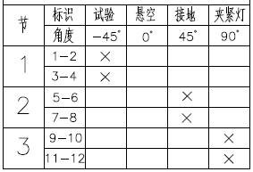
TABLE 1
The high-voltage test wiring loop and the medium-voltage test wiring loop are respectively provided with a high-voltage end screen test loop and a medium-voltage end screen test loop shown in figures 9 and 10, and the state indication tables are shown in table 2.

TABLE 2
The invention integrates the transfer box 1 with a plurality of test detections and the electric lifting wire take-up and pay-off platform 2, and the wiring and the test wiring during the test of the transformer are convenient, fast, safe and fast.
It should be noted that, regarding the specific structure of the present invention, the connection relationship between the modules adopted in the present invention is determined and can be realized, except for the specific description in the embodiment, the specific connection relationship can bring the corresponding technical effect, and the technical problem proposed by the present invention is solved on the premise of not depending on the execution of the corresponding software program.
Finally, it should be noted that: the above embodiments are only used to illustrate the technical solution of the present invention, and not to limit the same; while the invention has been described in detail and with reference to the foregoing embodiments, it will be understood by those skilled in the art that: the technical solutions described in the foregoing embodiments may still be modified, or some or all of the technical features may be equivalently replaced; and the modifications or the substitutions do not make the essence of the corresponding technical solutions depart from the scope of the technical solutions of the embodiments of the present invention.
Claims (10)
1. Integrated form electrical test device, including transfer box (1) and receive and release line platform (2), its characterized in that: the junction box (1) comprises a box body (11) and a cover body used for covering the box body, wherein a high-voltage wire inlet port (12) and a low-voltage wire inlet port (13) which are isolated from each other are arranged on two side faces of the box body (11), an operation panel (14) used for testing a junction end of wiring is arranged on the box body (11), and test items or other test loops are switched in the box body (11);
the wire winding and unwinding platform (2) comprises a wire box (21), a foldable lifting support (22) is arranged inside the wire box (21), a wire hanging platform (23) is arranged at the top end of the foldable lifting support (22), and a wire clamping mechanism (24) is arranged on the wire hanging platform (23);
the high-voltage wire inlet port (12) and the low-voltage wire inlet port (13) are connected with one end of a cable and are connected with the transfer box (1), the other end of the cable is placed on the wire take-up and pay-off platform (2) through the wire clamping mechanism (24), the wire take-up and pay-off platform (2) is fixed with equipment through a hanging chain after rising to a specified height, and the other end of the cable can be connected to the equipment in a telescopic mode through the wire clamping mechanism (24).
2. The integrated electrical testing apparatus of claim 1, wherein: the test circuit comprises a detection circuit capable of switching alternating current (220V) to direct current (5V), and the switching of the detection circuit is realized by the mutual matching of a selector switch (1431) and an indicator lamp (1432) which are arranged on a low-voltage test wiring switching end (143) on an operation panel (14).
3. The integrated electrical testing apparatus of claim 2, wherein: the high-voltage testing and medium-voltage testing system is characterized in that a high-voltage testing wiring transfer end (141) and a medium-voltage testing wiring transfer end (142) are arranged on the operation panel (14), and a testing line plug (144), a testing lamp (145), a change-over switch (146) and a 3D printing sleeve (147) are arranged on the high-voltage testing wiring transfer end (141) and the medium-voltage testing wiring transfer end (142);
the high-voltage test wiring transfer end (141) and the medium-voltage test wiring transfer end (142) are further respectively provided with a high-voltage end screen wiring transfer end (1411) and a medium-voltage end screen wiring transfer end (1421).
4. The integrated electrical testing apparatus of claim 3, wherein: the high-voltage end screen wiring transfer end (1411) comprises a high-voltage end screen outgoing terminal and a high-voltage end screen ungrounded switch, and the medium-voltage end screen wiring transfer end (1421) comprises a medium-voltage end screen outgoing terminal and a medium-voltage end screen ungrounded switch.
5. The integrated electrical testing apparatus of claim 4, wherein: the operation panel (14) is also provided with a power interface (148) and a test switch (149).
6. The integrated electrical testing apparatus of claim 1, wherein: the bottom of line case (21) is still through folding support base (211) of bolt fixedly connected with, folding support base (211) is including a plurality of supporting wheels (2101) and a plurality of landing leg (2102), supporting wheels (2101) are fixed on folding support base (211), the one end of landing leg (2102) is through axis of rotation and folding support base (211) swing joint, the other end of landing leg (2102) and the one end swing joint of supporting legs (2103), supporting legs (2103) are through the folding connection of movable connecting rod (2104) at landing leg (2101) end.
7. The integrated electrical testing apparatus of claim 6, wherein: the foldable lifting support (22) is specifically arranged as a scissor-type lifting support, at least two electric push rods (2201) are arranged on the foldable lifting support (22), each electric push rod (2201) comprises a controller, and the controllers are connected with the rechargeable batteries through wires.
8. The integrated electrical testing apparatus of claim 7, wherein: the wire take-up and pay-off platform (2) is further provided with a remote controller, the remote controller is connected with the controller through a wireless communication module, and the electric push rod (2201) is remotely controlled to complete lifting and withdrawing of the foldable lifting support (22).
9. The integrated electrical testing apparatus of claim 1, wherein: the wire hanging platform (23) comprises a tray (231), the wire clamping mechanism (24) comprises a wire clamping rod (241) and a bundle coil (242), a sliding groove (232) is formed in the bottom of the tray (231), the tray (231) is fixedly connected with one end of an X-folding frame at the top end of the foldable lifting support (22), and the other end of the X-folding frame is in sliding connection with the sliding groove (232);
the wire clamping rods (241) are arranged at two ends of the inner side of the tray (231), and the beam coil (242) is provided with a plurality of beams which are respectively arranged at the front side of the tray (231).
10. The integrated electrical testing apparatus of claim 9, wherein: and arc rolling wheels used for preventing the test wire from being damaged in the drawing process are arranged at the platform folding corners of the wire hanging platform (23).
Priority Applications (1)
| Application Number | Priority Date | Filing Date | Title |
|---|---|---|---|
| CN202011295968.3A CN112578199A (en) | 2020-11-18 | 2020-11-18 | Integrated electrical testing device |
Applications Claiming Priority (1)
| Application Number | Priority Date | Filing Date | Title |
|---|---|---|---|
| CN202011295968.3A CN112578199A (en) | 2020-11-18 | 2020-11-18 | Integrated electrical testing device |
Publications (1)
| Publication Number | Publication Date |
|---|---|
| CN112578199A true CN112578199A (en) | 2021-03-30 |
Family
ID=75122869
Family Applications (1)
| Application Number | Title | Priority Date | Filing Date |
|---|---|---|---|
| CN202011295968.3A Pending CN112578199A (en) | 2020-11-18 | 2020-11-18 | Integrated electrical testing device |
Country Status (1)
| Country | Link |
|---|---|
| CN (1) | CN112578199A (en) |
Cited By (2)
| Publication number | Priority date | Publication date | Assignee | Title |
|---|---|---|---|---|
| CN114113689A (en) * | 2021-11-08 | 2022-03-01 | 广东电网有限责任公司广州供电局 | Intelligent tray device based on integrated electrical detection wiring module |
| CN114323662A (en) * | 2021-12-07 | 2022-04-12 | 绵阳创格科技有限公司 | Switching device between test piece and test bench fixed equipment |
Citations (14)
| Publication number | Priority date | Publication date | Assignee | Title |
|---|---|---|---|---|
| CN2480226Y (en) * | 2001-03-13 | 2002-03-06 | 国家电力公司武汉高压研究所 | Moveable power supply vehicle |
| CN101833055A (en) * | 2010-05-07 | 2010-09-15 | 国家电网公司直流建设分公司 | Method and system for testing low pressure increase of converter valve equipment |
| CN201741500U (en) * | 2010-05-21 | 2011-02-09 | 湖北正奥汽车附件有限公司 | Movable wiring frame |
| CN201754169U (en) * | 2010-06-29 | 2011-03-02 | 河南省电力公司平顶山供电公司 | Lifting type test car |
| CN104215835A (en) * | 2014-09-18 | 2014-12-17 | 杭州西湖电子研究所 | Automatic measuring system for main transformer |
| CN205301457U (en) * | 2015-11-26 | 2016-06-08 | 广西电网有限责任公司南宁供电局 | On -vehicle electric power testboard of synthesizing of box removal |
| CN206304076U (en) * | 2016-08-09 | 2017-07-07 | 上海中科再启医疗设备有限公司 | Movable cart lowering or hoisting gear |
| CN107895943A (en) * | 2017-10-16 | 2018-04-10 | 霍尼韦尔环境自控产品(天津)有限公司 | Device and its control method with wiring protection function |
| CN207664543U (en) * | 2017-11-16 | 2018-07-27 | 西安美育信息科技有限公司 | A kind of network engineering wiring cable tube bank fixing device |
| CN108957041A (en) * | 2018-07-17 | 2018-12-07 | 国网河南省电力公司南阳供电公司 | A kind of intelligent substation high pressure seton device and application method |
| CN208596219U (en) * | 2018-06-20 | 2019-03-12 | 三峡大学 | Auxiliary device suitable for substation field calibrating mutual inductor |
| CN111478253A (en) * | 2020-04-14 | 2020-07-31 | 江苏天安智联科技股份有限公司 | High-safety protective device for vehicle-mounted audio surround circuit and using method |
| CN211655598U (en) * | 2020-04-20 | 2020-10-09 | 保定市中联通信技术有限公司 | Adjustable cable fixing device for power communication |
| CN211687773U (en) * | 2019-11-19 | 2020-10-16 | 安徽益佳通电池有限公司 | Lithium battery module pencil hanging wire device |
-
2020
- 2020-11-18 CN CN202011295968.3A patent/CN112578199A/en active Pending
Patent Citations (14)
| Publication number | Priority date | Publication date | Assignee | Title |
|---|---|---|---|---|
| CN2480226Y (en) * | 2001-03-13 | 2002-03-06 | 国家电力公司武汉高压研究所 | Moveable power supply vehicle |
| CN101833055A (en) * | 2010-05-07 | 2010-09-15 | 国家电网公司直流建设分公司 | Method and system for testing low pressure increase of converter valve equipment |
| CN201741500U (en) * | 2010-05-21 | 2011-02-09 | 湖北正奥汽车附件有限公司 | Movable wiring frame |
| CN201754169U (en) * | 2010-06-29 | 2011-03-02 | 河南省电力公司平顶山供电公司 | Lifting type test car |
| CN104215835A (en) * | 2014-09-18 | 2014-12-17 | 杭州西湖电子研究所 | Automatic measuring system for main transformer |
| CN205301457U (en) * | 2015-11-26 | 2016-06-08 | 广西电网有限责任公司南宁供电局 | On -vehicle electric power testboard of synthesizing of box removal |
| CN206304076U (en) * | 2016-08-09 | 2017-07-07 | 上海中科再启医疗设备有限公司 | Movable cart lowering or hoisting gear |
| CN107895943A (en) * | 2017-10-16 | 2018-04-10 | 霍尼韦尔环境自控产品(天津)有限公司 | Device and its control method with wiring protection function |
| CN207664543U (en) * | 2017-11-16 | 2018-07-27 | 西安美育信息科技有限公司 | A kind of network engineering wiring cable tube bank fixing device |
| CN208596219U (en) * | 2018-06-20 | 2019-03-12 | 三峡大学 | Auxiliary device suitable for substation field calibrating mutual inductor |
| CN108957041A (en) * | 2018-07-17 | 2018-12-07 | 国网河南省电力公司南阳供电公司 | A kind of intelligent substation high pressure seton device and application method |
| CN211687773U (en) * | 2019-11-19 | 2020-10-16 | 安徽益佳通电池有限公司 | Lithium battery module pencil hanging wire device |
| CN111478253A (en) * | 2020-04-14 | 2020-07-31 | 江苏天安智联科技股份有限公司 | High-safety protective device for vehicle-mounted audio surround circuit and using method |
| CN211655598U (en) * | 2020-04-20 | 2020-10-09 | 保定市中联通信技术有限公司 | Adjustable cable fixing device for power communication |
Cited By (2)
| Publication number | Priority date | Publication date | Assignee | Title |
|---|---|---|---|---|
| CN114113689A (en) * | 2021-11-08 | 2022-03-01 | 广东电网有限责任公司广州供电局 | Intelligent tray device based on integrated electrical detection wiring module |
| CN114323662A (en) * | 2021-12-07 | 2022-04-12 | 绵阳创格科技有限公司 | Switching device between test piece and test bench fixed equipment |
Similar Documents
| Publication | Publication Date | Title |
|---|---|---|
| CN112578199A (en) | Integrated electrical testing device | |
| CN202383217U (en) | Integrated test bench of transformer | |
| CN106451224A (en) | Method for replacing metal oxide arrester of live working robot | |
| CN107284488B (en) | Test trolley with pole setting function | |
| CN203705590U (en) | Floor-type special device for withstand voltage tests of safety equipment | |
| CN204166086U (en) | A kind of multifunctional low-voltage line fault searches instrument | |
| CN203326326U (en) | 220kV transformer test short-circuit wire connector | |
| CN209044024U (en) | A kind of test device of breaker | |
| CN207123596U (en) | A kind of fuse detection means | |
| CN202572183U (en) | Large-current telescopic high-altitude cable connecting clamp | |
| CN203037783U (en) | On-off detection apparatus for secondary cable core of current transformer | |
| CN213986555U (en) | Integrated type electric high-voltage test wiring conversion device | |
| CN205104688U (en) | High -voltage line wire support | |
| CN112595875B (en) | Voltage acquisition and transmission system for high-voltage insulating part | |
| CN111458565A (en) | Medium loss and insulation resistance test conversion device | |
| CN207067247U (en) | A kind of p-wire storage device for DCR of Transformer three-phase direct tester | |
| CN211880145U (en) | Direct current system charging module switching device | |
| CN218240152U (en) | Hand push test car lift test wire frame | |
| CN109950830A (en) | The provision for disengagement of hot line robot arrester and method | |
| CN208329557U (en) | Distribution automation workbench | |
| CN219039144U (en) | General type switch cabinet circuit breaker handcart secondary circuit test adapter | |
| CN112909822B (en) | Unmanned aerial vehicle-assisted uninterrupted power supply operation system and method for power distribution network | |
| CN204760571U (en) | Electric earth connection is tested to quick reputation of distribution | |
| CN111064021B (en) | CT check lead hanging arm | |
| CN109270331A (en) | A kind of engineering high voltage electroscope |
Legal Events
| Date | Code | Title | Description |
|---|---|---|---|
| PB01 | Publication | ||
| PB01 | Publication | ||
| SE01 | Entry into force of request for substantive examination | ||
| SE01 | Entry into force of request for substantive examination |