CN112564740B - Device for detecting advanced application function of HPLC - Google Patents
Device for detecting advanced application function of HPLC Download PDFInfo
- Publication number
- CN112564740B CN112564740B CN202011406233.3A CN202011406233A CN112564740B CN 112564740 B CN112564740 B CN 112564740B CN 202011406233 A CN202011406233 A CN 202011406233A CN 112564740 B CN112564740 B CN 112564740B
- Authority
- CN
- China
- Prior art keywords
- phase
- module
- serial port
- platform area
- monitoring tool
- Prior art date
- Legal status (The legal status is an assumption and is not a legal conclusion. Google has not performed a legal analysis and makes no representation as to the accuracy of the status listed.)
- Active
Links
Images


Classifications
-
- H—ELECTRICITY
- H04—ELECTRIC COMMUNICATION TECHNIQUE
- H04B—TRANSMISSION
- H04B3/00—Line transmission systems
- H04B3/54—Systems for transmission via power distribution lines
-
- H—ELECTRICITY
- H04—ELECTRIC COMMUNICATION TECHNIQUE
- H04B—TRANSMISSION
- H04B17/00—Monitoring; Testing
- H04B17/30—Monitoring; Testing of propagation channels
- H04B17/309—Measuring or estimating channel quality parameters
- H04B17/345—Interference values
-
- H—ELECTRICITY
- H04—ELECTRIC COMMUNICATION TECHNIQUE
- H04L—TRANSMISSION OF DIGITAL INFORMATION, e.g. TELEGRAPHIC COMMUNICATION
- H04L43/00—Arrangements for monitoring or testing data switching networks
- H04L43/04—Processing captured monitoring data, e.g. for logfile generation
- H04L43/045—Processing captured monitoring data, e.g. for logfile generation for graphical visualisation of monitoring data
-
- H—ELECTRICITY
- H04—ELECTRIC COMMUNICATION TECHNIQUE
- H04L—TRANSMISSION OF DIGITAL INFORMATION, e.g. TELEGRAPHIC COMMUNICATION
- H04L69/00—Network arrangements, protocols or services independent of the application payload and not provided for in the other groups of this subclass
- H04L69/22—Parsing or analysis of headers
Abstract
The invention particularly relates to a device for detecting an HPLC (high performance liquid chromatography) deepened application function, which comprises a platform area 1, a platform area 2 and a platform area merging unit, wherein a field power utilization environment is simulated through the platform area 1 and the platform area 2, the platform area 1 can simulate a field platform area 5-layer network routing level, and when the platform area 1 and the platform area 2 are merged through the platform area merging unit, the field platform area 6-layer network routing level can be simulated, so that the functions of high-frequency data acquisition function detection, power failure active reporting detection, clock accurate management detection, phase topology identification function detection, platform area automatic identification, ID unified identification management, automatic file synchronization, communication performance monitoring and network optimization are realized, the detection result is accurate, manual analysis is not needed, and the operation is simple and convenient.
Description
Technical Field
The invention relates to the technical field of electric power, in particular to a device for detecting an HPLC (high performance liquid chromatography) deepened application function.
Background
In a detection laboratory, in order to monitor the communication messages between the module and the ammeter, the traditional detection mode is that the module is directly connected with a module serial port through a welding wire harness, then the communication messages are read through an observation oscilloscope, and the communication messages are manually analyzed, so that the operation is complicated, and errors are easy to occur.
High-speed, interconnected and intercommunicated low-voltage power line carrier communication technology is mainly applied to a low-voltage power distribution network, is called low-voltage high-speed power line carrier communication, and is used for detecting and verifying advanced application functions of HPLC.
Disclosure of Invention
In order to overcome the defects or shortcomings in the prior art, the invention provides the device for detecting the advanced application function of the HPLC, which can simulate the field power utilization environment, has accurate detection result, does not need manual analysis, is simple and convenient to operate, and ensures the matching of the laboratory detection standard and the actual application scene.
In order to achieve the above object, the present invention provides an apparatus for detecting HPLC advanced application function, comprising a platform area 1, a platform area 2 and a platform area merging unit, wherein:
the platform area 1 is used for simulating a field power utilization environment and can simulate 5-layer network routing levels of the field platform area,
the transformer area 2 is used for simulating the field power utilization environment, can simulate the 6-layer network routing level of the field transformer area when being combined with the transformer area 1 for use,
the platform area merging unit is used for merging the platform area 1 and the platform area 2;
the platform area 1 comprises shielding boxes 1 to 6, a function generator 1, connecting units 1 to 5, an oscilloscope 1, a power source 1 and a serial server 1, wherein:
a function generator 1 for outputting various interference signals, testing communication attenuation resistance, white noise interference, narrow-band interference, pulse interference and frequency offset interference,
a connecting unit 1 to 5 for connecting the shield boxes 1 to 6,
an oscilloscope 1 for observing the power line signals generated by the apparatus for the concentrator and the electricity meter,
the shielding boxes 1 to 6 are connected through the connecting units 1 to 5, the shielding boxes 1 to 6 and the connecting units 1 to 5 are respectively connected with the serial server 1, the serial server 1 is connected with an upper computer, the shielding box 1 is connected with the power source 1, the power source 1 is connected with the station area merging unit, the function generator 1 is connected with the connecting unit 1, and the oscilloscope 1 is connected with the connecting unit 5;
platform district 2 contains shielded cell 7, shielded cell 8, power source 2 and serial server 2, wherein:
the shielding boxes 7 and 8 are connected with each other and are simultaneously connected with the serial server 2 respectively, the serial server 2 is connected with an upper computer, the shielding box 7 is connected with the power source 2, and the power source 2 is connected with the transformer area merging unit;
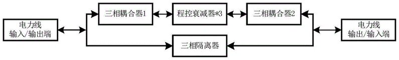
the platform area merging unit comprises 1 three-phase isolator, 2 three-phase couplers, 3 programmable attenuators and 2 three-phase voltage phase sequence control boards, and a power line voltage input/output end is respectively connected to the three-phase couplers 1 and the three-phase voltage line sequence control boards 1; the output of the three-phase coupler 1 is connected with the input ends of the 3 programmable attenuators, and the output ends of the 3 programmable attenuators are connected with the input end of the three-phase coupler 2; the output end of the three-phase voltage phase sequence control plate 1 is connected to the input end of a three-phase isolator, and the output end of the three-phase isolator is connected to the input end of a three-phase voltage phase sequence control plate 2; the output end of the three-phase coupler 2 and the output end of the three-phase voltage phase sequence control board 2 are respectively connected with the output/input end of the power line voltage, and when the transformer areas 1 and 2 are not combined, the automatic identification function of the transformer areas can be simulated.
Further, connection units 1 to 5 for achieving an adjustable attenuation of the power line carrier signal each comprise 1 three-phase isolator, 2 three-phase couplers and 3 programmable attenuators, wherein:
the three-phase isolator is used for isolating the power carrier signal;
the three-phase coupler is used for isolating strong electricity and extracting power carrier signals;
the programmable attenuator is used for attenuating power carrier signals, the attenuation degree is 0-90dB, the attenuation step is 1dB, and the programmable attenuator is communicated with an upper computer through RS232 to realize adjustable attenuation;
the power line voltage input/output end is respectively connected with the input ends of the three-phase coupler 1 and the three-phase isolator, the output end of the three-phase coupler 1 is connected with the input ends of the 3 programmable attenuators, the output end of the 3 programmable attenuators is connected with the input end of the three-phase coupler 2, and the output end of the three-phase coupler 2 and the output end of the three-phase isolator are respectively connected with the power line voltage output/input end.
Further, the shielding box 1 or the shielding box 7 comprises a concentrator epitope unit 1 set, a three-phase epitope unit 1 set and a single-phase epitope unit 9 set, wherein:
the concentrator epitope unit comprises an isolation CT 1 set, a three-phase voltage phase sequence control board 1 block, a current automatic short circuit control board 1 block, a concentrator 1 block, a routing module serial port monitoring tool 1 set, a 4G module serial port monitoring tool 1 set, a routing module 1 block and a 4G module 1 block and is used for simulating a field summary table; the power line current passes through the isolation CT and is connected to a current terminal of the concentrator; the power line voltage is connected to a concentrator voltage terminal through a three-phase voltage phase sequence control board, a routing module serial port monitoring tool is installed in a concentrator routing module bin, a routing module is installed on the routing module serial port monitoring tool, a 4G module serial port monitoring tool is installed in a concentrator 4G module bin, and a 4G module is installed on the 4G module serial port monitoring tool;
the single-phase epitope unit or the three-phase epitope unit comprises an isolation CT 1 set, a three-phase voltage phase sequence control board 1 block, a current automatic short circuit control board 1 block, a single-phase meter or a three-phase meter 1 block, a single-phase or three-phase module serial port monitoring tool 1 set and a single-phase module or three-phase module 1 block, and is used for simulating a single-phase sub meter or a three-phase sub meter on site;
the 4G module serial port monitoring tool is used for monitoring message transmission between the master station and the concentrator and communicating with the upper computer through RS 232;
the routing module serial port monitoring tool is used for monitoring message transmission between the concentrator and the routing module and communicating with an upper computer through RS 232;
the three-phase module serial port monitoring tool is used for monitoring message transmission between the three-phase meter and the three-phase module and communicating with an upper computer through RS 232;
the single-phase module serial port monitoring tool is used for monitoring message transmission between the single-phase meter and the single-phase module and communicating with an upper computer through RS 232;
the three-phase voltage phase sequence control board is used for controlling ABC phase sequence and power-off or power-on actions, and is communicated with the upper computer through RS 485;
the current automatic short circuit control panel is used for detecting an external current loop and controlling a current short circuit relay to realize independent control of the meter position, automatically short circuit the meter position when the meter is not selected, does not influence normal test of other meter positions, and communicates with an upper computer through RS 485;
the isolation CT is used for sensing the current of the current line loop to the current input end of the single-phase meter or the three-phase meter;
the 4G module serial port monitoring tool, the routing module serial port monitoring tool, the three-phase module serial port monitoring tool, the single module serial port monitoring tool and the three-phase voltage phase sequence control board are respectively connected with the serial server 1.
Further, the shielding boxes 2, 3, 4, 5, 6 or the shielding boxes 8 each comprise a set of three-phase epitope units 2 and a set of single-phase epitope units 9.
Further, power source 1 or power source 2, for providing a three-phase four-wire voltage of 0V-380V, in the range of 3 (0.1-120) A current, 45-55Hz frequency and 0-360 ° phase.
Further, the serial server 1 or the serial server 2 is used for realizing that all the epitope communication channels are completely independent and supporting simultaneous communication of multiple epitopes.
Further, the shield boxes 1 to 6 or the shield boxes 7, 8 are used for mounting a concentrator, a three-phase meter, a single-phase meter, and various circuit boards, while being capable of shielding external interference signals.
The invention has the beneficial effects that:
1. the method can set detection equipment parameters, a self-defined detection scheme, arbitrarily control a power source, interference equipment and detection equipment, perform statistical analysis on detection data and output a detection report, ensure one-to-one matching of the detection standard of a laboratory and an actual application scene, and improve the real reliability of a simulation field.
2. Messages transmitted between the master station and the concentrator, between the concentrator and the CCO, between the CCO and each meter STA and between the STA and the electric meter can be monitored, Q/GDW 1376.1, Q/GDW 1376.2, an object-oriented communication protocol, a DL/T645 communication protocol and HPLC related protocol messages can be analyzed, online real-time monitoring of the communication messages is achieved, and testing accuracy is improved.
3. The power line signals generated by the concentrator and the ammeter can be monitored by the monitoring device, so that carrier communication signals are visualized and convenient to observe.
4. The epitope is independently controlled, and when the epitope is not selected, the epitope is automatically short-circuited, and the normal test of other epitopes is not influenced. All the epitope communication channels are completely independent, and multi-epitope simultaneous communication is supported, so that the test efficiency is improved.
5. Detection of application functions is deepened: the method comprises the steps of high-frequency data acquisition function detection, power failure active reporting detection, clock accurate management detection, phase topology identification function detection, station area automatic identification, ID unified identification management, archive automatic synchronization, communication performance monitoring and network optimization, automatic testing is realized, and labor and time costs are saved.
Drawings
Fig. 1 is a system block diagram of the device for detecting the HPLC advanced application function of the present invention.
Fig. 2 is a block diagram of a shielding box structure of the device for detecting the HPLC advanced application function of the present invention.
FIG. 3 is a structural diagram of a concentrator epitope unit of the device for detecting the HPLC deepening application function according to the present invention.
FIG. 4 is a block diagram of the structure of a single-phase table or three-phase epitope unit of the device for detecting the advanced application function of HPLC.
Fig. 5 is a structural block diagram of a serial port monitoring tool of the device for detecting the HPLC advanced application function of the present invention.
Fig. 6 is a block diagram of the connection unit structure of the device for detecting the HPLC advanced application function of the present invention.
Fig. 7 is a block diagram of a station area merging unit structure of the device for detecting HPLC advanced application functions according to the present invention.
Detailed Description
In order to make the objects, technical solutions and advantages of the present invention more apparent, the present invention is further described in detail below with reference to the accompanying drawings and embodiments. It should be understood that the specific embodiments described herein are merely illustrative of the invention and do not limit the invention.
As shown in fig. 1, an apparatus for detecting HPLC advanced application function includes a platform area 1, a platform area 2 and a platform area merging unit, and is characterized in that:
the platform area 1 is used for simulating a field power utilization environment and can simulate a field platform area 5-layer network routing level;
the transformer area 2 is used for simulating a field power utilization environment and can simulate a 6-layer network routing level of the field transformer area when being combined with the transformer area 1 for use;
and the platform area merging unit is used for merging the platform area 1 and the platform area 2.
Platform district 1 contains shielded cell 1 to 6, function generator 1, connecting element 1 to 5, oscilloscope 1, power source 1 and serial servers 1, wherein:
the function generator 1 can output various interferences for testing communication attenuation resistance, white noise interference, narrow-band interference, pulse interference and frequency offset interference.
Connection units 1 to 5 for connecting the shield boxes 1 to 6;
the oscilloscope 1 is used for observing power line signals generated by the device for the concentrator and the ammeter;
the shielding boxes 1 to 6 are connected through the connecting units 1 to 5, the shielding boxes 1 to 6 and the connecting units 1 to 5 are respectively connected with the serial server 1, the serial server 1 is connected with an upper computer, the shielding box 1 is connected with the power source 1, the power source 1 is connected with the platform area merging unit, the function generator 1 is connected with the connecting unit 1, and the oscilloscope 1 is connected with the connecting unit 5.
Platform district 2 contains shielded cell 7, shielded cell 8, power source 2 and serial server 2, wherein:
the shielding boxes 7 and 8 are connected with each other and are simultaneously connected with the serial server 2 respectively, the serial server 2 is connected with an upper computer, the shielding box 7 is connected with the power source 2, and the power source 2 is connected with the transformer area merging unit.
The shield boxes 1 to 6 or the shield boxes 7, 8 are used for mounting a concentrator, a three-phase meter, a single-phase meter, and various circuit boards while being capable of shielding external interference signals.
As shown in fig. 2, the shielding box 1 or the shielding box 7 includes a set of the concentrator epitope unit 1, a set of the three-phase epitope unit 1, and a set of the single-phase epitope unit 9. Wherein:
the concentrator epitope unit comprises an isolation CT 1 set, a three-phase voltage phase sequence control board 1 block, a current automatic short circuit control board 1 block, a concentrator 1 block, a routing module serial port monitoring tool 1 set, a 4G module serial port monitoring tool 1 set, a routing module 1 block and a 4G module 1 block and is used for simulating a field summary table;
the single-phase epitope unit or the three-phase epitope unit comprises an isolation CT 1 set, a three-phase voltage phase sequence control board 1 block, a current automatic short circuit control board 1 block, a single-phase meter or a three-phase meter 1 block, a single-phase or three-phase module serial port monitoring tool 1 set and a single-phase module or three-phase module 1 block, and is used for simulating a single-phase sub meter or a three-phase sub meter on site;
the 4G module serial port monitoring tool is used for monitoring message transmission between the master station and the concentrator and communicating with the upper computer through RS 232;
the routing module serial port monitoring tool is used for monitoring message transmission between the concentrator and the routing module and communicating with an upper computer through RS 232;
the three-phase module serial port monitoring tool is used for monitoring message transmission between the three-phase meter and the three-phase module and communicating with an upper computer through RS 232;
the single-phase module serial port monitoring tool is used for monitoring message transmission between the single-phase meter and the single-phase module and communicating with an upper computer through RS 232;
the three-phase voltage phase sequence control board is used for controlling the ABC phase sequence and the power-off or power-on actions and is communicated with the upper computer through RS 485;
the current automatic short circuit control panel is used for detecting an external current loop and controlling a current short circuit relay to realize independent control of the meter position, automatically short circuit the meter position when the meter is not selected, does not influence normal test of other meter positions, and communicates with an upper computer through RS 485;
the isolation CT is used for mutually sensing the current of the current line loops to be the current input end of the single-phase meter or the three-phase meter;
the 4G module serial port monitoring tool, the routing module serial port monitoring tool, the three-phase module serial port monitoring tool, the single module serial port monitoring tool and the three-phase voltage phase sequence control board are respectively connected with the serial server 1.
Shielding boxes 2, 3, 4, 5, 6 or 8, each containing a set of three-phase epitope units 2 and a set of single-phase epitope units 9.
As shown in fig. 3, the concentrator epitope unit is shown, the power line current passes through the isolation CT, the voltage passes through the three-phase voltage phase sequence control board, and then is respectively connected to the concentrator current and voltage terminals, the routing module serial port monitoring tool is installed in the concentrator routing module bin, the 4G module serial port monitoring tool is installed in the concentrator 4G module bin, the routing module is installed on the routing module serial port monitoring tool, and the 4G module is installed on the 4G module serial port monitoring tool; the 4G module serial port monitoring tool is used for monitoring message transmission between the master station and the concentrator; the routing module serial port monitoring tool is used for monitoring message transmission between the concentrator and the routing module; and the three-phase voltage phase sequence control board is used for controlling the ABC phase sequence and the power-off or power-on actions and is communicated with the upper computer through RS 485. The isolation CT is used to sense the current of the current line loops to each other at the concentrator current input. The automatic short circuit control panel of electric current for detect external current return circuit and control current short circuit relay, realize epitope independent control, when not choosing the table, this epitope of automatic short circuit does not influence other epitope normal tests, carries out the communication through RS485 with the host computer.
As shown in fig. 4, the single-phase/three-phase meter unit is shown, wherein power line current passes through an isolation CT, voltage passes through a three-phase voltage phase sequence control board, and then is respectively connected to a single-phase meter/three-phase meter current and voltage terminal, a single-phase/three-phase module serial port monitoring tool is installed in an electric meter carrier module bin, and a single-phase module/three-phase module is installed on the single-phase/three-phase module serial port monitoring tool; the three-phase module serial port monitoring tool is used for monitoring message transmission between the three-phase meter and the three-phase module; the single-phase module serial port monitoring tool is used for monitoring message transmission between the single-phase meter and the single-phase module; and the three-phase voltage phase sequence control board is used for controlling ABC phase sequence and power-off or power-on actions and is communicated with the upper computer through RS 485. The isolation CT is used to mutually sense the current of the current line loops to the single-phase meter/three-phase meter current input. The automatic short circuit control panel of electric current for detect external current return circuit and control current short circuit relay, realize epitope independent control, when not choosing the table, this epitope of automatic short circuit does not influence other epitope normal tests, carries out the communication through RS485 with the host computer.
As shown in fig. 5, the serial port monitoring tool is composed of 4 parts, namely a serial port monitoring tool bottom shell, a serial port monitoring tool top shell and serial port monitoring adapter plates 1 and 2 respectively; the serial port monitoring adapter plate 1 is installed on a serial port monitoring tool bottom shell, the serial port monitoring adapter plate 2 is in butt joint with the serial port monitoring adapter plate 1 through a connector, and a serial port monitoring tool top shell is fixed on the serial port monitoring adapter plate 2; the routing, 4G, three-phase and single-phase module serial port monitoring tool is designed in the same structure. The serial port monitoring tool is communicated with an upper computer through RS232, and the purpose of monitoring the serial port to receive and send messages is achieved.
As shown in fig. 6, the connection units 1 to 5 are used for realizing adjustable attenuation of power line carrier signals, each of which includes 1 three-phase isolator, 2 three-phase couplers and 3 programmable attenuators, the power line voltage input/output ends are respectively connected to the three-phase couplers 1 and the three-phase isolator input ends, the three-phase coupler 1 output is connected to the 3 programmable attenuators input ends, the 3 programmable attenuators output ends are connected to the three-phase coupler 2 input ends, the three-phase coupler 2 output ends and the three-phase isolator output ends are respectively connected to the power line voltage output/input ends, wherein:
the three-phase isolator is used for isolating power carrier signals;
the three-phase coupler is used for isolating strong current and extracting a power carrier signal;
the programmable attenuator is used for attenuating power carrier signals, the attenuation degree is 0-90dB, the attenuation step is 1dB, and the programmable attenuator is communicated with an upper computer through RS232 to achieve adjustable attenuation.
As shown in fig. 7, the station area merging unit includes 1 three-phase isolator, 2 three-phase couplers, 3 programmable attenuators, and 2 three-phase voltage phase sequence control boards, and when the station areas 1 and 2 are not merged, the automatic station area identification function can be simulated. The power line voltage input/output end is respectively connected with the three-phase coupler 1 and the three-phase voltage line sequence control board 1; the output of the three-phase coupler 1 is connected with the input ends of the 3 programmable attenuators, and the output ends of the 3 programmable attenuators are connected with the input end of the three-phase coupler 2; the output end of the three-phase voltage phase sequence control plate 1 is connected to the input end of a three-phase isolator, and the output end of the three-phase isolator is connected to the input end of a three-phase voltage phase sequence control plate 2; the output end of the three-phase coupler 2 and the output end of the three-phase voltage phase sequence control board 2 are respectively connected to the output/input end of the power line voltage. And (3) realizing HPLC deepened application function detection: the method comprises the following steps of high-frequency data acquisition function detection, power failure active reporting detection, clock accurate management detection, phase topology identification function detection, station area automatic identification, ID unified identification management, file automatic synchronization, communication performance monitoring and network optimization.
The above-mentioned embodiments are illustrative of the specific embodiments of the present invention, and are not restrictive, and those skilled in the relevant art can make various changes and modifications to obtain corresponding equivalent technical solutions without departing from the spirit and scope of the present invention, so that all equivalent technical solutions should be included in the scope of the present invention.
Claims (7)
1. A device for detecting the advanced application function of HPLC comprises a platform area 1, a platform area 2 and a platform area merging unit, and is characterized in that:
the platform area 1 is used for simulating a field power utilization environment and can simulate 5-layer network routing levels of the field platform area,
the transformer area 2 is used for simulating the field power utilization environment, can simulate the 6-layer network routing level of the field transformer area when being combined with the transformer area 1 for use,
the platform area merging unit is used for merging the platform area 1 and the platform area 2;
platform district 1 contains shielded cell 1 to 6, function generator 1, connecting element 1 to 5, oscilloscope 1, power source 1 and serial server 1, wherein:
a function generator 1 for outputting various interference signals, testing communication attenuation resistance, white noise interference, narrow-band interference, pulse interference and frequency offset interference,
a connecting unit 1 to 5 for connecting the shield boxes 1 to 6,
an oscilloscope 1 for observing the power line signal generated by the device for the concentrator and the electric meter,
the shielding boxes 1 to 6 are connected through the connecting units 1 to 5, the shielding boxes 1 to 6 and the connecting units 1 to 5 are respectively connected with the serial server 1, the serial server 1 is connected with an upper computer, the shielding box 1 is connected with the power source 1, the power source 1 is connected with the platform area merging unit, the function generator 1 is connected with the connecting unit 1, and the oscilloscope 1 is connected with the connecting unit 5;
platform district 2 contains shielded cell 7, shielded cell 8, power source 2 and serial port server 2, wherein:
the shielding boxes 7 and 8 are connected with each other and are simultaneously connected with the serial server 2 respectively, the serial server 2 is connected with an upper computer, the shielding box 7 is connected with the power source 2, and the power source 2 is connected with the transformer area merging unit;
the station area merging unit comprises 1 three-phase isolator, 2 three-phase couplers, 3 program-controlled attenuators and 2 three-phase voltage phase sequence control boards, and a power line voltage input/output end is respectively connected to the three-phase couplers 1 and the three-phase voltage line sequence control boards 1; the output of the three-phase coupler 1 is connected with the input ends of the 3 programmable attenuators, and the output ends of the 3 programmable attenuators are connected with the input end of the three-phase coupler 2; the output end of the three-phase voltage phase sequence control plate 1 is connected to the input end of a three-phase isolator, and the output end of the three-phase isolator is connected to the input end of a three-phase voltage phase sequence control plate 2; the output end of the three-phase coupler 2 and the output end of the three-phase voltage phase sequence control board 2 are respectively connected to a power line voltage output/input end, and when the transformer areas 1 and 2 are not combined, the automatic identification function of the transformer areas can be simulated.
2. The apparatus for testing advanced HPLC application functions of claim 1, wherein said connection units 1 to 5 for adjustable attenuation of power line carrier signals each comprise 1 three-phase isolator, 2 three-phase couplers and 3 programmable attenuators, wherein:
the three-phase isolator is used for isolating power carrier signals;
the three-phase coupler is used for isolating strong current and extracting a power carrier signal;
the programmable attenuator is used for attenuating power carrier signals, the attenuation degree is 0-90dB, the attenuation step is 1dB, and the programmable attenuator is communicated with an upper computer through RS232 to realize adjustable attenuation;
the power line voltage input/output end is respectively connected with the input ends of the three-phase coupler 1 and the three-phase isolator, the output end of the three-phase coupler 1 is connected with the input ends of the 3 programmable attenuators, the output end of the 3 programmable attenuators is connected with the input end of the three-phase coupler 2, and the output end of the three-phase coupler 2 and the output end of the three-phase isolator are respectively connected with the power line voltage output/input end.
3. The device for detecting the advanced application function of HPLC according to claim 1, wherein said shielding box 1 or shielding box 7 comprises a concentrator epitope unit 1 set, a three-phase epitope unit 1 set and a single-phase epitope unit 9 set, wherein:
the concentrator epitope unit comprises an isolation CT 1 set, a three-phase voltage phase sequence control board 1 block, a current automatic short circuit control board 1 block, a concentrator 1 block, a routing module serial port monitoring tool 1 set, a 4G module serial port monitoring tool 1 set, a routing module 1 block and a 4G module 1 block and is used for simulating a field summary table; the power line current passes through the isolation CT and is connected to a current terminal of the concentrator; the power line voltage is connected to a concentrator voltage terminal through a three-phase voltage phase sequence control board, a routing module serial port monitoring tool is installed in a concentrator routing module bin, a routing module is installed on the routing module serial port monitoring tool, a 4G module serial port monitoring tool is installed in a concentrator 4G module bin, and a 4G module is installed on the 4G module serial port monitoring tool;
the single-phase epitope unit or the three-phase epitope unit comprises an isolation CT 1 set, a three-phase voltage phase sequence control board 1 block, a current automatic short circuit control board 1 block, a single-phase meter or a three-phase meter 1 block, a single-phase or three-phase module serial port monitoring tool 1 set and a single-phase module or three-phase module 1 block, and is used for simulating a single-phase sub meter or a three-phase sub meter on site;
the 4G module serial port monitoring tool is used for monitoring message transmission between the master station and the concentrator and communicating with the upper computer through RS 232;
the routing module serial port monitoring tool is used for monitoring message transmission between the concentrator and the routing module and communicating with an upper computer through RS 232;
the three-phase module serial port monitoring tool is used for monitoring message transmission between the three-phase meter and the three-phase module and communicating with an upper computer through RS 232;
the single-phase module serial port monitoring tool is used for monitoring message transmission between the single-phase meter and the single-phase module and communicating with an upper computer through RS 232;
the three-phase voltage phase sequence control board is used for controlling the ABC phase sequence and the power-off or power-on actions and is communicated with the upper computer through RS 485;
the current automatic short circuit control panel is used for detecting an external current loop and controlling a current short circuit relay to realize independent control of the epitope, automatically short circuit the epitope when the epitope is not selected, does not influence normal test of other epitopes, and communicates with an upper computer through RS 485;
the isolation CT is used for mutually sensing the current of the current line loops to be the current input end of the single-phase meter or the three-phase meter;
the 4G module serial port monitoring tool, the routing module serial port monitoring tool, the three-phase module serial port monitoring tool, the single module serial port monitoring tool and the three-phase voltage phase sequence control board are respectively connected with the serial server 1.
4. An apparatus for testing HPLC deepening application functions according to claim 2 or 3, characterized in that the shielding boxes 2, 3, 4, 5, 6 or 8 each contain 2 sets of three-phase epitope units and 9 sets of single-phase epitope units.
5. A device for testing HPLC advanced application functionality according to claim 2 or 3, wherein said power source 1 or power source 2 is adapted to provide a three-phase four-wire voltage of 0V-380V, with a current range of 3 x (0.1-120) a, 45-55Hz frequency and 0-360 ° phase.
6. The device for detecting the advanced application function of HPLC according to claim 2 or 3, wherein said serial server 1 or 2 is used to realize that all epitope communication channels are completely independent and support multi-epitope simultaneous communication.
7. An apparatus for testing advanced HPLC application functions according to claim 2 or 3, wherein said shielding boxes 1 to 6 or 7, 8 are used for mounting concentrators, three-phase meters, single-phase meters and various circuit boards, while being capable of shielding external interference signals.
Priority Applications (1)
| Application Number | Priority Date | Filing Date | Title |
|---|---|---|---|
| CN202011406233.3A CN112564740B (en) | 2020-12-05 | 2020-12-05 | Device for detecting advanced application function of HPLC |
Applications Claiming Priority (1)
| Application Number | Priority Date | Filing Date | Title |
|---|---|---|---|
| CN202011406233.3A CN112564740B (en) | 2020-12-05 | 2020-12-05 | Device for detecting advanced application function of HPLC |
Publications (2)
| Publication Number | Publication Date |
|---|---|
| CN112564740A CN112564740A (en) | 2021-03-26 |
| CN112564740B true CN112564740B (en) | 2022-07-15 |
Family
ID=75048227
Family Applications (1)
| Application Number | Title | Priority Date | Filing Date |
|---|---|---|---|
| CN202011406233.3A Active CN112564740B (en) | 2020-12-05 | 2020-12-05 | Device for detecting advanced application function of HPLC |
Country Status (1)
| Country | Link |
|---|---|
| CN (1) | CN112564740B (en) |
Families Citing this family (3)
| Publication number | Priority date | Publication date | Assignee | Title |
|---|---|---|---|---|
| CN113746501B (en) * | 2021-09-14 | 2023-07-25 | 北京中睿昊天信息科技有限公司 | Test method for evaluating high-speed power line carrier HPLC deepening application function |
| CN113824472B (en) * | 2021-09-30 | 2022-09-16 | 广东电网有限责任公司 | Method and device for testing relay of power line carrier communication path and storage medium |
| CN114221676A (en) * | 2021-11-17 | 2022-03-22 | 国网内蒙古东部电力有限公司供电服务监管与支持中心 | Advanced function detection platform of HPLC (high performance liquid chromatography) intelligent meter |
Citations (1)
| Publication number | Priority date | Publication date | Assignee | Title |
|---|---|---|---|---|
| CN109547065A (en) * | 2018-10-30 | 2019-03-29 | 国网北京市电力公司 | Platform area identifying system and its recognition methods |
Family Cites Families (5)
| Publication number | Priority date | Publication date | Assignee | Title |
|---|---|---|---|---|
| WO2017063180A1 (en) * | 2015-10-16 | 2017-04-20 | 瑞斯康微电子(深圳)有限公司 | Power line carrier communication performance detection device |
| CN109256856B (en) * | 2018-09-06 | 2020-07-03 | 石家庄科林电气股份有限公司 | Power line broadband carrier (HPLC) based station area topology identification system and method |
| CN109361427B (en) * | 2018-10-30 | 2021-08-20 | 国网北京市电力公司 | Simulation test device and method |
| CN110429991A (en) * | 2019-07-16 | 2019-11-08 | 国网江苏省电力有限公司电力科学研究院 | A kind of electrical energy data acquiring emulation test system |
| CN110518938A (en) * | 2019-08-01 | 2019-11-29 | 国网上海市电力公司 | A kind of low-voltage network power line carrier communication performance test simulation system |
-
2020
- 2020-12-05 CN CN202011406233.3A patent/CN112564740B/en active Active
Patent Citations (1)
| Publication number | Priority date | Publication date | Assignee | Title |
|---|---|---|---|---|
| CN109547065A (en) * | 2018-10-30 | 2019-03-29 | 国网北京市电力公司 | Platform area identifying system and its recognition methods |
Non-Patent Citations (1)
| Title |
|---|
| 基于HPLC通信模块的智能电表深化应用研究;邱志辉等;《江西电力》;20181025(第10期);全文 * |
Also Published As
| Publication number | Publication date |
|---|---|
| CN112564740A (en) | 2021-03-26 |
Similar Documents
| Publication | Publication Date | Title |
|---|---|---|
| CN112564740B (en) | Device for detecting advanced application function of HPLC | |
| WO2013010447A1 (en) | Carrier communication test device | |
| CN105785199A (en) | Multifunctional power distribution terminal integrated test system and operating method thereof | |
| CN103076520A (en) | Dynamic analogue simulation detection platform and analogue simulation method for secondary system of intelligent substation | |
| CN101206601B (en) | I/o port testing device | |
| CN110161331B (en) | Detection platform for primary and secondary fusion complete equipment and control method | |
| CN203811795U (en) | Remote detection system for electric energy metering information of transformer station | |
| CN110429991A (en) | A kind of electrical energy data acquiring emulation test system | |
| CN105203870A (en) | Intelligent transformer substation secondary equipment integrated test system based on power line communication | |
| CN203949994U (en) | Relay protection test and simulation control device | |
| CN105510737A (en) | Universal automatic testing system for carrier rocket | |
| CN109613906A (en) | Third generation intelligent substation observing and controlling handset test macro and its application method | |
| CN110176947A (en) | A kind of the communication failure diagnosis terminal and method of low pressure carrier wave module | |
| CN103513223A (en) | Electric energy meter communication interface load capacity test system | |
| CN103516448A (en) | Collection terminal communication interface load capacity test system | |
| CN103076560B (en) | Electrical test equipment non-contact measurement combination unit and application thereof | |
| CN105405281A (en) | Detection method for carrier communication failures of smart electric meter | |
| CN111948478B (en) | Power distribution terminal detection system and method under real working condition | |
| CN103995207A (en) | Three-remote automatic test device for power distribution terminal | |
| CN107612642A (en) | A kind of signal band and out-of-band interference level method of testing | |
| CN110297162A (en) | A kind of communication power grid detection system | |
| CN209710088U (en) | A kind of communication failure diagnosis terminal of low pressure carrier wave module | |
| CN102759674B (en) | Universal adapter for testing optocouplers | |
| CN112436903A (en) | Test system | |
| CN105403847A (en) | Voltage monitoring system based on FPGA technology and verification method |
Legal Events
| Date | Code | Title | Description |
|---|---|---|---|
| PB01 | Publication | ||
| PB01 | Publication | ||
| SE01 | Entry into force of request for substantive examination | ||
| SE01 | Entry into force of request for substantive examination | ||
| GR01 | Patent grant | ||
| GR01 | Patent grant |