CN112563809B - Bending connector - Google Patents
Bending connector Download PDFInfo
- Publication number
- CN112563809B CN112563809B CN202011531549.5A CN202011531549A CN112563809B CN 112563809 B CN112563809 B CN 112563809B CN 202011531549 A CN202011531549 A CN 202011531549A CN 112563809 B CN112563809 B CN 112563809B
- Authority
- CN
- China
- Prior art keywords
- plug
- flexible sealing
- cable
- shell
- sealing sleeve
- Prior art date
- Legal status (The legal status is an assumption and is not a legal conclusion. Google has not performed a legal analysis and makes no representation as to the accuracy of the status listed.)
- Active
Links
Images




Classifications
-
- H—ELECTRICITY
- H01—ELECTRIC ELEMENTS
- H01R—ELECTRICALLY-CONDUCTIVE CONNECTIONS; STRUCTURAL ASSOCIATIONS OF A PLURALITY OF MUTUALLY-INSULATED ELECTRICAL CONNECTING ELEMENTS; COUPLING DEVICES; CURRENT COLLECTORS
- H01R13/00—Details of coupling devices of the kinds covered by groups H01R12/70 or H01R24/00 - H01R33/00
- H01R13/46—Bases; Cases
- H01R13/52—Dustproof, splashproof, drip-proof, waterproof, or flameproof cases
- H01R13/5219—Sealing means between coupling parts, e.g. interfacial seal
- H01R13/5221—Sealing means between coupling parts, e.g. interfacial seal having cable sealing means
-
- H—ELECTRICITY
- H01—ELECTRIC ELEMENTS
- H01R—ELECTRICALLY-CONDUCTIVE CONNECTIONS; STRUCTURAL ASSOCIATIONS OF A PLURALITY OF MUTUALLY-INSULATED ELECTRICAL CONNECTING ELEMENTS; COUPLING DEVICES; CURRENT COLLECTORS
- H01R13/00—Details of coupling devices of the kinds covered by groups H01R12/70 or H01R24/00 - H01R33/00
- H01R13/40—Securing contact members in or to a base or case; Insulating of contact members
- H01R13/42—Securing in a demountable manner
-
- H—ELECTRICITY
- H01—ELECTRIC ELEMENTS
- H01R—ELECTRICALLY-CONDUCTIVE CONNECTIONS; STRUCTURAL ASSOCIATIONS OF A PLURALITY OF MUTUALLY-INSULATED ELECTRICAL CONNECTING ELEMENTS; COUPLING DEVICES; CURRENT COLLECTORS
- H01R13/00—Details of coupling devices of the kinds covered by groups H01R12/70 or H01R24/00 - H01R33/00
- H01R13/46—Bases; Cases
- H01R13/50—Bases; Cases formed as an integral body
-
- H—ELECTRICITY
- H01—ELECTRIC ELEMENTS
- H01R—ELECTRICALLY-CONDUCTIVE CONNECTIONS; STRUCTURAL ASSOCIATIONS OF A PLURALITY OF MUTUALLY-INSULATED ELECTRICAL CONNECTING ELEMENTS; COUPLING DEVICES; CURRENT COLLECTORS
- H01R13/00—Details of coupling devices of the kinds covered by groups H01R12/70 or H01R24/00 - H01R33/00
- H01R13/46—Bases; Cases
- H01R13/52—Dustproof, splashproof, drip-proof, waterproof, or flameproof cases
- H01R13/5202—Sealing means between parts of housing or between housing part and a wall, e.g. sealing rings
-
- H—ELECTRICITY
- H01—ELECTRIC ELEMENTS
- H01R—ELECTRICALLY-CONDUCTIVE CONNECTIONS; STRUCTURAL ASSOCIATIONS OF A PLURALITY OF MUTUALLY-INSULATED ELECTRICAL CONNECTING ELEMENTS; COUPLING DEVICES; CURRENT COLLECTORS
- H01R13/00—Details of coupling devices of the kinds covered by groups H01R12/70 or H01R24/00 - H01R33/00
- H01R13/46—Bases; Cases
- H01R13/52—Dustproof, splashproof, drip-proof, waterproof, or flameproof cases
- H01R13/521—Sealing between contact members and housing, e.g. sealing insert
-
- H—ELECTRICITY
- H01—ELECTRIC ELEMENTS
- H01R—ELECTRICALLY-CONDUCTIVE CONNECTIONS; STRUCTURAL ASSOCIATIONS OF A PLURALITY OF MUTUALLY-INSULATED ELECTRICAL CONNECTING ELEMENTS; COUPLING DEVICES; CURRENT COLLECTORS
- H01R13/00—Details of coupling devices of the kinds covered by groups H01R12/70 or H01R24/00 - H01R33/00
- H01R13/46—Bases; Cases
- H01R13/52—Dustproof, splashproof, drip-proof, waterproof, or flameproof cases
- H01R13/5213—Covers
-
- H—ELECTRICITY
- H01—ELECTRIC ELEMENTS
- H01R—ELECTRICALLY-CONDUCTIVE CONNECTIONS; STRUCTURAL ASSOCIATIONS OF A PLURALITY OF MUTUALLY-INSULATED ELECTRICAL CONNECTING ELEMENTS; COUPLING DEVICES; CURRENT COLLECTORS
- H01R13/00—Details of coupling devices of the kinds covered by groups H01R12/70 or H01R24/00 - H01R33/00
- H01R13/62—Means for facilitating engagement or disengagement of coupling parts or for holding them in engagement
-
- H—ELECTRICITY
- H01—ELECTRIC ELEMENTS
- H01R—ELECTRICALLY-CONDUCTIVE CONNECTIONS; STRUCTURAL ASSOCIATIONS OF A PLURALITY OF MUTUALLY-INSULATED ELECTRICAL CONNECTING ELEMENTS; COUPLING DEVICES; CURRENT COLLECTORS
- H01R13/00—Details of coupling devices of the kinds covered by groups H01R12/70 or H01R24/00 - H01R33/00
- H01R13/62—Means for facilitating engagement or disengagement of coupling parts or for holding them in engagement
- H01R13/629—Additional means for facilitating engagement or disengagement of coupling parts, e.g. aligning or guiding means, levers, gas pressure electrical locking indicators, manufacturing tolerances
- H01R13/631—Additional means for facilitating engagement or disengagement of coupling parts, e.g. aligning or guiding means, levers, gas pressure electrical locking indicators, manufacturing tolerances for engagement only
- H01R13/6315—Additional means for facilitating engagement or disengagement of coupling parts, e.g. aligning or guiding means, levers, gas pressure electrical locking indicators, manufacturing tolerances for engagement only allowing relative movement between coupling parts, e.g. floating connection
Landscapes
- Connector Housings Or Holding Contact Members (AREA)
Abstract
The present invention relates to an elbow connector. An elbow connector comprising: the connector shell comprises a plug-in shell and a wiring shell, and the plug-in shell and the wiring shell are connected together in a set angle; the rear end of the inserting shell is provided with an opening, and the opening is connected with a buckle cover matched with the opening; further comprising: the plug core component comprises a plug core, a cable and a flexible sealing sleeve, wherein the plug core is arranged in the plug-in shell, the cable is arranged in the wiring shell, and the flexible sealing sleeve is connected between the plug core and the cable; the inner side of one end of the flexible sealing sleeve is connected with the inserting core in a sealing mode, and the inner side of the other end of the flexible sealing sleeve is connected with the cable in a sealing mode. The bent connector does not need to be provided with sealing structures at the opening and on the wiring shell respectively, so that the structure is simplified, the bent connector is simple and convenient to assemble, and the production efficiency is improved. Moreover, the structure of the flexible sealing sleeve is relatively regular, so that the flexible sealing sleeve is convenient to machine and form, and the machining cost is reduced.
Description
Technical Field
The present invention relates to an elbow connector.
Background
At present, the connector applied to the outdoor communication equipment can be divided into the following parts according to the structural form of the cable protection part: straight connectors, hose transition connectors, and bent connectors.
As shown in fig. 1, when the cable 103 is routed, the cable 103 is first bent at a certain angle at the tail end of the straight connector 102 and then routed, and the routing space H required by the straight connector 102 is limited by the bending radius of the cable 103 itself1Large and not suitable for high-density wiring requirements.
As shown in fig. 2, when the cable 203 is wired, the cable 203 and the hose of the hose adaptor connector 202 are bent at a certain angle, and then the wiring is performed, and the wiring space H required by the hose adaptor connector 202 is limited by the bending radius of the cable 203 and the hose2Large and not suitable for high-density wiring requirements.
The structure of the bent connector 302 connected to the outdoor communication device 301 is shown in fig. 3, and when the cable 303 is wired, the cable 303 does not need to be bent, and the wiring space H required for the bent connector 3023The wiring structure is small and suitable for high-density wiring requirements.
Due to the curved arrangement of the plug housing of the angled connector, the installation of the ferrule component is difficult. In order to solve the problems, the chinese patent application with application publication No. CN106384906A discloses an elbow connector, which includes a connector housing, the connector housing includes a plug end housing and a terminal housing, the terminal housing is connected with the plug end housing at a set angle, the terminal housing is provided with a cable sealing structure, the rear end of the connector housing is provided with an opening, the opening is provided with a tail cover adapted to the shape of the opening, the tail cover includes an upper portion whose axis coincides with the axis of the plug end housing and a lower portion whose axis is parallel to the axis of the terminal housing and whose cross section is a fan-shaped ring; and a sealing gasket is arranged between the butt joint surface of the tail cover and the opening.
Above-mentioned curved connector is in order to guarantee sealing performance, not only need set up sealed the pad between tailcap and open-ended butt joint face, but also need set up cable seal structure on the wiring end casing, not only makes curved connector's leakproofness be difficult to guarantee, leads to curved connector's equipment comparatively complicated moreover, influences production efficiency. In addition, the sealing gasket between the butt joint surfaces of the tail cover and the opening is a special-shaped sealing gasket, so that the manufacturing cost of the sealing gasket is high, and the sealing performance is not easy to guarantee.
Disclosure of Invention
The invention aims to provide a bent connector, which aims to solve the technical problem that the sealing performance of the bent connector in the prior art is not easy to ensure.
In order to achieve the purpose, the technical scheme of the bending connector is as follows:
an elbow connector comprising:
the connector shell comprises a plug-in shell and a wiring shell, and the plug-in shell and the wiring shell are connected together in a set angle;
the rear end of the inserting shell is provided with an opening, and the opening is connected with a buckle cover matched with the opening;
further comprising:
the plug core component comprises a plug core, a cable and a flexible sealing sleeve, wherein the plug core is arranged in the plug-in shell, the cable is arranged in the wiring shell, and the flexible sealing sleeve is connected between the plug core and the cable;
the inner side of one end of the flexible sealing sleeve is connected with the inserting core in a sealing mode, and the inner side of the other end of the flexible sealing sleeve is connected with the cable in a sealing mode, so that the inserting core component is sealed.
The beneficial effects are that: according to the bent connector, the flexible sealing sleeve is arranged in the connector shell, so that the inner side of one end of the flexible sealing sleeve is connected with the inserting core in a sealing mode, and the inner side of the other end of the flexible sealing sleeve is connected with the cable in a sealing mode, the inserting core component is sealed, sealing structures do not need to be arranged at the opening and on the wiring shell respectively, the structure of the bent connector is simplified, the bent connector is easy and convenient to assemble, and the production efficiency is improved. Moreover, the structure of the flexible sealing sleeve is relatively regular, so that the flexible sealing sleeve is convenient to machine and form, and the machining cost is reduced.
Furthermore, the inner side and the outer side of the two ends of the flexible sealing sleeve are respectively provided with a sealing ring platform.
The beneficial effects are that: further ensuring the sealing performance.
Further, the middle part of the flexible sealing sleeve is of a corrugated structure.
The beneficial effects are that: by the design, the inserting core and the cable are conveniently bent to a set angle.
Furthermore, the lock pin comprises a positioning seat, a splicing positioning ring groove is formed in the positioning seat, a splicing positioning ring table is arranged on the inner side of the flexible sealing sleeve, and the splicing positioning ring groove is in positioning fit with the splicing positioning ring table to prevent the flexible sealing sleeve from being separated from the lock pin.
The beneficial effects are that: by the design, the stability of the sealing connection between the flexible sealing sleeve and the positioning seat can be ensured.
Further, the core insert comprises a plug, and the plug is in floating assembly on the positioning seat.
The beneficial effects are that: the plug can float when being plugged, which is beneficial to the plugging of the inserting core and improves the universality.
Furthermore, the ferrule component further comprises a fixing sleeve, the fixing sleeve is sleeved on the outer side of the cable and fixedly connected with the cable, and the cable is connected with the inner side of the flexible sealing sleeve in a sealing mode through the fixing sleeve.
The beneficial effects are that: by adding the fixing sleeve, the cable can resist certain pulling force.
Furthermore, the fixed sleeve is provided with a wiring positioning ring groove, the inner side of the flexible sealing sleeve is provided with a wiring positioning ring platform, and the wiring positioning ring groove is in positioning fit with the wiring positioning ring platform so as to prevent the flexible sealing sleeve from being separated from the fixed sleeve.
The beneficial effects are that: by the design, the stability of the sealing connection between the flexible sealing sleeve and the fixed sleeve can be ensured.
Furthermore, the buckle cover is fixedly connected to the opening through a clamping structure.
The beneficial effects are that: the design is convenient for the disassembly and the assembly of the buckle cover.
Furthermore, one end of the buckle cover is hinged on the opening, and the other end of the buckle cover is fixed on the opening through a clamping structure.
The beneficial effects are that: by the design, the connector shell is integrated, and the buckle cover is not easy to lose.
Furthermore, the buckle cover comprises a plug-in shell matching section and a wiring shell matching section, and the wiring shell matching section and the wiring shell are symmetrically arranged with the center line of the cable.
The beneficial effects are that: this arrangement further facilitates installation of the ferrule member into the connector housing.
Drawings
Fig. 1 is a schematic structural diagram of a straight connector connected to an outdoor communication device in the prior art;
FIG. 2 is a schematic diagram of a prior art hose adapter connector connected to an outdoor communication device;
fig. 3 is a schematic structural view illustrating a prior art bent connector connected to an outdoor communication device;
fig. 4 is an exploded view of an embodiment 1 of the inventive angle connector;
FIG. 5 is a schematic view of the connector housing of FIG. 4;
FIG. 6 is a schematic view of the insert core member of FIG. 4;
FIG. 7 is a cross-sectional view of the plug housing of FIG. 4;
FIG. 8 is a cross-sectional view of the wiring housing of FIG. 4;
fig. 9 is a schematic view of a connector housing of embodiment 2 of the inventive flex connector;
FIG. 10 is a bottom view of FIG. 9;
fig. 11 is a schematic view of a connector housing of embodiment 3 of the inventive flex connector;
fig. 12 is a schematic view of a connector housing of embodiment 4 of the inventive flex connector;
in fig. 1: 101. an outdoor communication device; 102. a straight connector; 103. a cable;
in fig. 2: 201. an outdoor communication device; 202. a hose adaptor connector; 203. a cable;
in fig. 3: 301. an outdoor communication device; 302. a flex connector; 303. a cable;
in fig. 4 to 8: 11. inserting the shell; 12. a wiring housing; 13. covering; 131. a mating section of the plug-in housing; 132. a wiring housing mating section; 14. inserting a core; 141. a plug; 142. positioning seats; 1421. inserting a positioning ring groove; 15. a cable; 16. a flexible sealing sleeve; 161. inserting a positioning ring platform; 162. a sealing ring table; 163. a wiring positioning ring platform; 17. a cable jacket; 18. a protrusion; 19. a card slot; 20. fixing a sleeve; 21. a pressure spring; 22. fixing a nut;
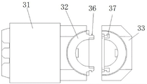
in fig. 9 and 10: 31. inserting the shell; 32. a wiring housing; 33. covering; 34. a positioning column; 35. positioning holes; 36. a hook is clamped; 37. a card slot;
in fig. 11: 41. inserting the shell; 42. a wiring housing; 43. covering; 44. bolt holes;
in fig. 12: 51. inserting the shell; 52. a wiring housing; 53. covering; 54. hinging a shaft; 55. a hook is clamped; 56. a clamping groove.
Detailed Description
In order to make the objects, technical solutions and advantages of the present invention more apparent, the present invention is described in further detail below with reference to the accompanying drawings and embodiments. It should be understood that the detailed description and specific examples, while indicating the preferred embodiment of the invention, are intended for purposes of illustration only and are not intended to limit the scope of the invention. The components of embodiments of the present invention generally described and illustrated in the figures herein may be arranged and designed in a wide variety of different configurations.
Thus, the following detailed description of the embodiments of the present invention, presented in the figures, is not intended to limit the scope of the invention, as claimed, but is merely representative of selected embodiments of the invention. All other embodiments, which can be derived by a person skilled in the art from the embodiments of the present invention without making any creative effort, shall fall within the protection scope of the present invention.
It is noted that relational terms such as "first" and "second," and the like, may be used solely to distinguish one entity or action from another entity or action without necessarily requiring or implying any actual such relationship or order between such entities or actions. Also, the terms "comprises," "comprising," or any other variation thereof, are intended to cover a non-exclusive inclusion, such that a process, method, article, or apparatus that comprises a list of elements does not include only those elements but may include other elements not expressly listed or inherent to such process, method, article, or apparatus. Without further limitation, an element defined by the phrase "comprising an … …" does not exclude the presence of other identical elements in a process, method, article, or apparatus that comprises the element. Furthermore, the terms "upper" and "lower" are based on the orientation and positional relationship shown in the drawings and are only for convenience of description of the present invention, and do not indicate that the referred device or component must have a specific orientation, and thus, should not be construed as limiting the present invention.
The features and properties of the present invention are described in further detail below with reference to examples.
Embodiment 1 of the inventive bent connector:
as shown in fig. 4 and 5, the elbow connector includes a connector housing and a ferrule member mounted within the connector housing; the connector housing includes a plug housing 11 and a terminal housing 12, the plug housing 11 having a ferrule chamber for accommodating a portion of the ferrule 14, and another portion of the ferrule 14 being exposed outside the connector housing. The connector housing may be made of metal or non-metal material.
In this embodiment, the plug housing 11 and the connection housing 12 are connected together at a predetermined angle, and preferably, the plug housing 11 and the connection housing 12 are arranged at 90 °. In other embodiments, the plug housing and the terminal housing may be disposed at an angle greater than 90 ° or less than 90 °, such as 120 °, 80 °, and the like.
In this embodiment, the insertion end of the insertion housing 11 is used as the front end, the rear end of the insertion housing 11 is provided with an opening, the connector housing further includes a fastening cover 13, and the fastening cover 13 is adapted to the opening and connected to the opening, so that the insertion core component can be conveniently installed in the connector housing.
As shown in fig. 4 and 5, the fastening cover 13 includes a plug housing matching section 131 and a connection housing matching section 132, the connection housing matching section 132 and the connection housing 12 are symmetrically arranged with respect to a center line of the cable 15, and after the fastening cover 13 is fastened at the opening, the connection housing matching section 132 and the connection housing 12 enclose a cable cavity for placing the cable 15. Wherein, the outer side surfaces of the connection casing matching section 132 and the connection casing 12 are both provided with threads.
In this embodiment, the insertion housing matching section 131 is provided with a clamping groove 19, the insertion housing 11 is provided with a protrusion 18, and the buckle cover 13 is in clamping fit with the clamping groove 19 through the protrusion 18 to be fixed at the opening. In this embodiment, the locking groove 19 and the protrusion 18 are arranged in pairs to ensure the stability of the locking cap 13. Wherein, the clamping groove 19 and the bulge 18 jointly form a clamping structure.
As shown in fig. 6, the ferrule assembly includes a ferrule 14, a cable 15, and a flexible sealing sleeve 16, the ferrule 14 being disposed within the ferrule chamber of the splice housing 11, the cable 15 being disposed within the cable chamber of the splice housing 12, the flexible sealing sleeve 16 being connected between the ferrule 14 and the cable 15.
As shown in fig. 4, 6 and 7, the ferrule 14 includes a plug 141 and a positioning seat 142, and a compression spring 21 is disposed between the plug 141 and the positioning seat 142, so that the plug 141 is floatingly assembled on the positioning seat 142, and can float when the plug 141 is plugged, which is beneficial to plugging the ferrule 14. In other embodiments, the plug and the positioning seat may be fixedly connected.
In this embodiment, the ferrule 14 is fixed in the plug housing 11 in a clamping manner, so as to prevent the ferrule 14 from moving relative to the plug housing 11 along the axial direction of the plug housing 11; the positioning seat 142 of the ferrule 14 is provided with an insertion positioning ring groove 1421, the inner side of the flexible sealing sleeve 16 is provided with an insertion positioning ring platform 61, and the insertion positioning ring groove 1421 is in positioning fit with the insertion positioning ring platform 161 to prevent the flexible sealing sleeve 16 from separating from the ferrule 14. In other embodiments, the inserting positioning ring groove and the inserting positioning ring table are not arranged, and the inner side of the flexible sealing sleeve is fixedly bonded on the outer peripheral surface of the positioning seat.
In order to ensure the sealing performance, sealing ring platforms 162 are provided on both the inner side and the outer side of the end of the flexible sealing sleeve 16, so that the inner side of the end of the flexible sealing sleeve 16 is connected with the positioning seat 142 of the ferrule 14 in a sealing manner, and the outer side of the end of the flexible sealing sleeve 16 is connected with the plug housing 11 in a sealing manner.
As shown in fig. 4, 6 and 8, the ferrule member further includes a fixing sleeve 20, the fixing sleeve 20 is sleeved on the outer side of the cable 15, and the fixing sleeve 20 is fixedly connected with the cable 15 by bonding or crimping, so that the cable 15 resists a certain pulling force. In other embodiments, no retaining sleeve may be provided.
In the present embodiment, the fixing sleeve 20 is clamped in the wiring housing 12 to prevent the cable 15 from moving relative to the wiring housing 12 along the axial direction of the wiring housing 12; the outer peripheral surface of the fixed sleeve 20 is provided with a wiring positioning ring groove, the inner side of the flexible sealing sleeve 16 is provided with a wiring positioning ring platform 163, and the wiring positioning ring groove is in positioning fit with the wiring positioning ring platform 163 to prevent the flexible sealing sleeve 16 from being separated from the fixed sleeve 20. In other embodiments, the wiring positioning ring groove and the wiring positioning ring table are not arranged, and the inner side of the flexible sealing sleeve is fixedly bonded on the outer peripheral surface of the fixing sleeve.
In order to ensure the sealing performance, a sealing ring 162 is provided on both the inside and outside of the end of the flexible sealing sleeve 16, so that the inside of the end of the flexible sealing sleeve 16 is connected with the fixing sleeve 20 in a sealing manner, and the outside of the end of the flexible sealing sleeve 16 is connected with the wiring housing 12 in a sealing manner.
As shown in fig. 6, the middle portion of the flexible sealing sleeve 16 is corrugated to facilitate bending of the ferrule 14 and cable 15 at 90 °. In other embodiments, the flexible sealing sleeve may be a uniform diameter sleeve.
In this embodiment, the flexible sealing sleeve 16 is a rubber sleeve. In other embodiments, the flexible sealing sleeve may be another flexible sleeve.
During assembly, the ferrule 14 of the ferrule component is firstly installed into the plug-in housing 11 from the opening, and then the flexible sealing sleeve 16 is bent, so that the ferrule 14 and the cable 15 form an angle of 90 degrees; then, the buckle cover 13 is clamped at the opening, and the fixing nut 22 is screwed on the wiring shell 12, so as to complete the installation of the bent connector. The cable sheath 17 is fixed to the connection housing 12 by a fixing nut 22 to protect the cable 15.
The bent connector in the embodiment is characterized in that the flexible sealing sleeve is arranged inside the connector shell, so that one end of the flexible sealing sleeve is connected with the inserting core in a sealing mode, the other end of the flexible sealing sleeve is connected with the cable in a sealing mode, sealing structures do not need to be arranged on the opening and the wiring shell respectively, the structure of the bent connector is simplified, the bent connector is simple and convenient to assemble, and production efficiency is improved. Moreover, the structure of the flexible sealing sleeve is relatively regular, so that the flexible sealing sleeve is convenient to machine and form, and the machining cost is reduced.
Embodiment 2 of the inventive flex connector:
the difference between this embodiment and embodiment 1 is that in embodiment 1, a clamping groove 19 is provided on the mating section 131 of the plug-in housing, a protrusion 18 is provided on the plug-in housing 11, and the buckle cover 13 is in clamping fit with the clamping groove 19 through the protrusion 18 to be fixed at the opening. In this embodiment, as shown in fig. 9 and 10, the fastening cover 33 is provided with a positioning hole 35 and a locking groove 37, the inserting casing 31 is provided with a positioning column 34, the wiring casing 32 is provided with a locking hook 36, and in the positioning and matching process of the positioning hole 35 and the positioning column 34, the fastening cover 33 is in locking fit with the locking groove 37 through the locking hook 36 so as to be fixed at the opening. Two sets of positioning holes 35, positioning posts 34, hooks 36 and slots 37 are provided.
Embodiment 3 of the inventive bent connector:
the difference between this embodiment and embodiment 1 is that in embodiment 1, a clamping groove 19 is provided on the mating section 131 of the plug-in housing, a protrusion 18 is provided on the plug-in housing 11, and the buckle cover 13 is in clamping fit with the clamping groove 19 through the protrusion 18 to be fixed at the opening. In this embodiment, as shown in fig. 11, the wiring housing 42 and the fastening cover 43 are both provided with bolt holes 44, and the fastening cover 43 is fixed at the opening by bolts. In other embodiments, a positioning hole may be disposed on the fastening cover 43, and a positioning column may be disposed on the insertion housing 41, and the positioning column is in positioning fit with the positioning hole to ensure the stability of the fastening cover 43. Wherein two sets of bolt holes 44 are provided.
Embodiment 4 of the inventive bent connector:
the difference between this embodiment and embodiment 1 is that in embodiment 1, a clamping groove 19 is provided on the mating section 131 of the plug-in housing, a protrusion 18 is provided on the plug-in housing 11, and the buckle cover 13 is in clamping fit with the clamping groove 19 through the protrusion 18 to be fixed at the opening. In this embodiment, as shown in fig. 12, the buckle cover 53 is hinged to the plug-in housing 51 through a hinge shaft 54, a clamping groove 56 is provided on the buckle cover 53, a clamping hook 55 is provided on the connection housing 52, and the buckle cover 53 is clamped and matched with the clamping groove 56 through the clamping hook 55 to be fixed at the opening. Wherein, two sets of clamping hooks 55 and clamping grooves 56 are provided.
Embodiment 5 of the inventive bent connector:
the present embodiment is different from embodiment 1 in that in embodiment 1, the inner side and the outer side of both ends of the flexible sealing sleeve 16 are provided with the sealing ring platforms 162, so that the inner side and the outer side of the flexible sealing sleeve 16 can be sealed. In this embodiment, only the inner sides of the two ends of the flexible sealing sleeve are provided with the sealing ring platforms, at this time, the inner side of one end of the flexible sealing sleeve is in sealing connection with the insertion core, the inner side of the other end of the flexible sealing sleeve is in sealing connection with the cable, and the outer sides of the two ends of the flexible sealing sleeve are subjected to a certain pressing force of the shell.
Embodiment 6 of the inventive bent connector:
the present embodiment is different from embodiment 1 in that, in embodiment 1, the buckle cover 13 includes a plug housing fitting section 131 and a wiring housing fitting section 132, and the wiring housing fitting section 132 and the wiring housing 12 are symmetrically arranged with respect to the center line of the cable 15. In this embodiment, the structure of the buckle cover is a tail cover structure disclosed in application publication No. CN 106384906A.
The above description is only a preferred embodiment of the present invention, and not intended to limit the present invention, the scope of the present invention is defined by the appended claims, and all equivalent structural changes made by using the contents of the specification and the drawings of the present invention should be covered by the scope of the present invention.
Claims (8)
1. An elbow connector comprising:
the connector shell comprises a plug-in shell (11) and a wiring shell (12), wherein the plug-in shell (11) and the wiring shell (12) are connected together in a set angle;
the inserting end of the inserting shell (11) is taken as the front end, the rear end of the inserting shell (11) is provided with an opening, and the opening is connected with a buckle cover (13) matched with the opening;
it is characterized by also comprising:
the plug core component comprises a plug core (14), a cable (15) and a flexible sealing sleeve (16), wherein the plug core (14) is arranged in the plug-in shell (11), the cable (15) is arranged in the wiring shell (12), and the flexible sealing sleeve (16) is connected between the plug core (14) and the cable (15);
the inner side of one end of the flexible sealing sleeve (16) is connected with the insertion core (14) in a sealing mode, the inner side of the other end of the flexible sealing sleeve (16) is connected with the cable (15) in a sealing mode to achieve sealing of the insertion core component, and sealing ring platforms (162) are arranged on the inner side and the outer side of two ends of the flexible sealing sleeve (16); the inserting core component further comprises a fixing sleeve (20), the fixing sleeve (20) is sleeved on the outer side of the cable (15) and fixedly connected with the cable (15), and the cable (15) is connected with the inner side of the flexible sealing sleeve (16) in a sealing mode through the fixing sleeve (20).
2. Elbow connector according to claim 1, characterized in that the middle part of the flexible sealing sleeve (16) is of a corrugated construction.
3. The elbow connector according to claim 1, wherein the ferrule (14) comprises a positioning seat (142), the positioning seat (142) is provided with a plugging positioning ring groove (1421), the flexible sealing sleeve (16) is provided with a plugging positioning ring platform (161) on the inner side, and the plugging positioning ring groove (1421) is in positioning fit with the plugging positioning ring platform (161) to prevent the flexible sealing sleeve (16) from separating from the ferrule (14).
4. The elbow connector according to claim 3, characterized in that the ferrule (14) comprises a plug (141), the plug (141) being float-fitted on the positioning socket (142).
5. The elbow connector as claimed in claim 1, wherein said retaining sleeve (20) is provided with a wire retention ring groove, and the flexible sealing sleeve (16) is provided with a wire retention ring abutment (163) on the inside thereof, the wire retention ring groove being in locating engagement with the wire retention ring abutment (163) to prevent the flexible sealing sleeve (16) from disengaging from the retaining sleeve (20).
6. The elbow connector as claimed in claim 1, wherein the cover (13) is fixedly connected to the opening by means of a snap-fit connection.
7. Elbow connector according to claim 1, characterized in that the cover (13) is hinged at one end to the opening and is fixed at the other end to the opening by means of a snap-fit construction.
8. The elbow connector as claimed in claim 1, characterized in that the snap-on cover (13) comprises a plug housing mating section (131) and a connection housing mating section (132), the connection housing mating section (132) being arranged symmetrically to the connection housing (12) with respect to the center line of the cable (15).
Priority Applications (1)
| Application Number | Priority Date | Filing Date | Title |
|---|---|---|---|
| CN202011531549.5A CN112563809B (en) | 2020-12-22 | 2020-12-22 | Bending connector |
Applications Claiming Priority (1)
| Application Number | Priority Date | Filing Date | Title |
|---|---|---|---|
| CN202011531549.5A CN112563809B (en) | 2020-12-22 | 2020-12-22 | Bending connector |
Publications (2)
| Publication Number | Publication Date |
|---|---|
| CN112563809A CN112563809A (en) | 2021-03-26 |
| CN112563809B true CN112563809B (en) | 2022-05-17 |
Family
ID=75032194
Family Applications (1)
| Application Number | Title | Priority Date | Filing Date |
|---|---|---|---|
| CN202011531549.5A Active CN112563809B (en) | 2020-12-22 | 2020-12-22 | Bending connector |
Country Status (1)
| Country | Link |
|---|---|
| CN (1) | CN112563809B (en) |
Families Citing this family (1)
| Publication number | Priority date | Publication date | Assignee | Title |
|---|---|---|---|---|
| CN113871929B (en) * | 2021-08-27 | 2024-05-28 | 中航光电科技股份有限公司 | Ultrashort bent plug and connector assembly |
Citations (16)
| Publication number | Priority date | Publication date | Assignee | Title |
|---|---|---|---|---|
| JP2002216862A (en) * | 2001-01-19 | 2002-08-02 | Yazaki Corp | Waterproof structure of connection part of electric wire and terminal, and waterproofing method |
| KR20110060797A (en) * | 2009-11-30 | 2011-06-08 | 니혼 고꾸 덴시 고교 가부시끼가이샤 | Connector |
| CN102498618A (en) * | 2009-07-22 | 2012-06-13 | 康宁吉伯股份有限公司 | Coaxial angle connector and related method |
| CN202453542U (en) * | 2011-12-23 | 2012-09-26 | 泰科电子(上海)有限公司 | Optical fiber connector |
| CN204154940U (en) * | 2014-08-28 | 2015-02-11 | 罗森伯格亚太电子有限公司 | Fiber optic connector assembly |
| CN104798260A (en) * | 2012-10-15 | 2015-07-22 | 德尔福国际业务卢森堡公司 | Electrical connection system |
| CN104904071A (en) * | 2012-12-17 | 2015-09-09 | 哈廷电子有限公司及两合公司 | Automobile charging plug |
| CN106384906A (en) * | 2016-10-27 | 2017-02-08 | 中航光电科技股份有限公司 | Angle connector |
| CN106450833A (en) * | 2016-11-08 | 2017-02-22 | 四川永贵科技有限公司 | Multi-core angle connector for motor and motor controller |
| CN106785596A (en) * | 2017-02-20 | 2017-05-31 | 天津艾琪兴海洋勘探科技发展有限公司 | A kind of cable connector |
| CN206708144U (en) * | 2017-04-10 | 2017-12-05 | 佛山市南海连冠金属塑料制品有限公司 | It is a kind of for the rigging-angle connector of cantilever and the attachment structure of connecting tube |
| CN108352653A (en) * | 2015-06-30 | 2018-07-31 | 蓬托斯海底连接器有限公司 | Cut cable fitting |
| CN207868482U (en) * | 2018-03-12 | 2018-09-14 | 宁波捷扬电器有限公司 | A kind of 90 degree of bend pipe connectors |
| CN109103683A (en) * | 2018-08-29 | 2018-12-28 | 江苏亨鑫科技有限公司 | Curved coaxial cable protecting device of roller |
| CN109713530A (en) * | 2019-01-21 | 2019-05-03 | 中航光电科技股份有限公司 | A kind of connector assembly |
| CN210212077U (en) * | 2019-01-27 | 2020-03-31 | 瑞拓电气(上海)有限公司 | Specific steering device for automobile wire harness |
Family Cites Families (1)
| Publication number | Priority date | Publication date | Assignee | Title |
|---|---|---|---|---|
| US7878832B2 (en) * | 2009-03-25 | 2011-02-01 | Culture Bright Ltd | Underwater connector with a deformable insertion member and a sealing member squeezed by a clamping member |
-
2020
- 2020-12-22 CN CN202011531549.5A patent/CN112563809B/en active Active
Patent Citations (16)
| Publication number | Priority date | Publication date | Assignee | Title |
|---|---|---|---|---|
| JP2002216862A (en) * | 2001-01-19 | 2002-08-02 | Yazaki Corp | Waterproof structure of connection part of electric wire and terminal, and waterproofing method |
| CN102498618A (en) * | 2009-07-22 | 2012-06-13 | 康宁吉伯股份有限公司 | Coaxial angle connector and related method |
| KR20110060797A (en) * | 2009-11-30 | 2011-06-08 | 니혼 고꾸 덴시 고교 가부시끼가이샤 | Connector |
| CN202453542U (en) * | 2011-12-23 | 2012-09-26 | 泰科电子(上海)有限公司 | Optical fiber connector |
| CN104798260A (en) * | 2012-10-15 | 2015-07-22 | 德尔福国际业务卢森堡公司 | Electrical connection system |
| CN104904071A (en) * | 2012-12-17 | 2015-09-09 | 哈廷电子有限公司及两合公司 | Automobile charging plug |
| CN204154940U (en) * | 2014-08-28 | 2015-02-11 | 罗森伯格亚太电子有限公司 | Fiber optic connector assembly |
| CN108352653A (en) * | 2015-06-30 | 2018-07-31 | 蓬托斯海底连接器有限公司 | Cut cable fitting |
| CN106384906A (en) * | 2016-10-27 | 2017-02-08 | 中航光电科技股份有限公司 | Angle connector |
| CN106450833A (en) * | 2016-11-08 | 2017-02-22 | 四川永贵科技有限公司 | Multi-core angle connector for motor and motor controller |
| CN106785596A (en) * | 2017-02-20 | 2017-05-31 | 天津艾琪兴海洋勘探科技发展有限公司 | A kind of cable connector |
| CN206708144U (en) * | 2017-04-10 | 2017-12-05 | 佛山市南海连冠金属塑料制品有限公司 | It is a kind of for the rigging-angle connector of cantilever and the attachment structure of connecting tube |
| CN207868482U (en) * | 2018-03-12 | 2018-09-14 | 宁波捷扬电器有限公司 | A kind of 90 degree of bend pipe connectors |
| CN109103683A (en) * | 2018-08-29 | 2018-12-28 | 江苏亨鑫科技有限公司 | Curved coaxial cable protecting device of roller |
| CN109713530A (en) * | 2019-01-21 | 2019-05-03 | 中航光电科技股份有限公司 | A kind of connector assembly |
| CN210212077U (en) * | 2019-01-27 | 2020-03-31 | 瑞拓电气(上海)有限公司 | Specific steering device for automobile wire harness |
Also Published As
| Publication number | Publication date |
|---|---|
| CN112563809A (en) | 2021-03-26 |
Similar Documents
| Publication | Publication Date | Title |
|---|---|---|
| US7670060B2 (en) | Plug connector with an adaptor housing for receiving a plug or socket arrangement | |
| US7338214B1 (en) | Method and apparatus for sealing fiber optic connectors for industrial applications | |
| US7326073B2 (en) | Adapter housing for connecting insert devices to a cable fitting | |
| US4564255A (en) | Strain relief device for an electrical plug connector | |
| US8573853B2 (en) | Plug assembly | |
| WO2021134971A1 (en) | Connector and optical fiber connection assembly | |
| US9425540B2 (en) | Housing for a contact device | |
| CN112563809B (en) | Bending connector | |
| US11327246B2 (en) | Optical fiber connector, prefabricated optical fiber, adapter, fiber termination box, and optical fiber connection assembly | |
| WO2011076601A1 (en) | Connector assembly | |
| CN214474089U (en) | LC type fiber connector with protective housing | |
| CN109273917B (en) | Waterproof connector female head and waterproof connector | |
| US20210281003A1 (en) | Contact Assembly For A Connector Housing, Connector Housing As Well As Connector Assembly And Modular Connector Set With Such A Connector Housing | |
| CN210607818U (en) | Waterproof vehicle-mounted cable wire connector | |
| CN111180925A (en) | Be applied to plug bush subassembly and connector of connector | |
| CN220439989U (en) | Waterproof signal connector | |
| CN205809357U (en) | A kind of SC fiber adapter | |
| CN220021721U (en) | Connector and vehicle | |
| CN220873911U (en) | Connector housing assembly, connector and connector assembly | |
| CN220753942U (en) | Adapter device | |
| CN220914644U (en) | Connector housing assembly, connector and connector assembly | |
| CN220368211U (en) | Cascade communication waterproof line group and cascade communication system | |
| CN211238600U (en) | Be applied to plug bush subassembly and connector of connector | |
| CN220042332U (en) | Electric connector combination | |
| CN216121045U (en) | Right-angle plug |
Legal Events
| Date | Code | Title | Description |
|---|---|---|---|
| PB01 | Publication | ||
| PB01 | Publication | ||
| SE01 | Entry into force of request for substantive examination | ||
| SE01 | Entry into force of request for substantive examination | ||
| GR01 | Patent grant | ||
| GR01 | Patent grant |