CN112551663B - a liquid handling device - Google Patents
a liquid handling device Download PDFInfo
- Publication number
- CN112551663B CN112551663B CN202011447608.0A CN202011447608A CN112551663B CN 112551663 B CN112551663 B CN 112551663B CN 202011447608 A CN202011447608 A CN 202011447608A CN 112551663 B CN112551663 B CN 112551663B
- Authority
- CN
- China
- Prior art keywords
- liquid
- pipe
- cyclone
- coagulation tank
- liquid inlet
- Prior art date
- Legal status (The legal status is an assumption and is not a legal conclusion. Google has not performed a legal analysis and makes no representation as to the accuracy of the status listed.)
- Active
Links
Images
Classifications
-
- C—CHEMISTRY; METALLURGY
- C02—TREATMENT OF WATER, WASTE WATER, SEWAGE, OR SLUDGE
- C02F—TREATMENT OF WATER, WASTE WATER, SEWAGE, OR SLUDGE
- C02F1/00—Treatment of water, waste water, or sewage
- C02F1/52—Treatment of water, waste water, or sewage by flocculation or precipitation of suspended impurities
-
- A—HUMAN NECESSITIES
- A23—FOODS OR FOODSTUFFS; TREATMENT THEREOF, NOT COVERED BY OTHER CLASSES
- A23L—FOODS, FOODSTUFFS OR NON-ALCOHOLIC BEVERAGES, NOT OTHERWISE PROVIDED FOR; PREPARATION OR TREATMENT THEREOF
- A23L2/00—Non-alcoholic beverages; Dry compositions or concentrates therefor; Preparation or treatment thereof
- A23L2/70—Clarifying or fining of non-alcoholic beverages; Removing unwanted matter
-
- A—HUMAN NECESSITIES
- A23—FOODS OR FOODSTUFFS; TREATMENT THEREOF, NOT COVERED BY OTHER CLASSES
- A23L—FOODS, FOODSTUFFS OR NON-ALCOHOLIC BEVERAGES, NOT OTHERWISE PROVIDED FOR; PREPARATION OR TREATMENT THEREOF
- A23L27/00—Spices; Flavouring agents or condiments; Artificial sweetening agents; Table salts; Dietetic salt substitutes; Preparation or treatment thereof
- A23L27/50—Soya sauce
-
- C—CHEMISTRY; METALLURGY
- C02—TREATMENT OF WATER, WASTE WATER, SEWAGE, OR SLUDGE
- C02F—TREATMENT OF WATER, WASTE WATER, SEWAGE, OR SLUDGE
- C02F1/00—Treatment of water, waste water, or sewage
- C02F1/38—Treatment of water, waste water, or sewage by centrifugal separation
-
- C—CHEMISTRY; METALLURGY
- C12—BIOCHEMISTRY; BEER; SPIRITS; WINE; VINEGAR; MICROBIOLOGY; ENZYMOLOGY; MUTATION OR GENETIC ENGINEERING
- C12H—PASTEURISATION, STERILISATION, PRESERVATION, PURIFICATION, CLARIFICATION OR AGEING OF ALCOHOLIC BEVERAGES; METHODS FOR ALTERING THE ALCOHOL CONTENT OF FERMENTED SOLUTIONS OR ALCOHOLIC BEVERAGES
- C12H1/00—Pasteurisation, sterilisation, preservation, purification, clarification, or ageing of alcoholic beverages
- C12H1/02—Pasteurisation, sterilisation, preservation, purification, clarification, or ageing of alcoholic beverages combined with removal of precipitate or added materials, e.g. adsorption material
- C12H1/06—Precipitation by physical means, e.g. by irradiation, vibrations
- C12H1/063—Separation by filtration
-
- C—CHEMISTRY; METALLURGY
- C12—BIOCHEMISTRY; BEER; SPIRITS; WINE; VINEGAR; MICROBIOLOGY; ENZYMOLOGY; MUTATION OR GENETIC ENGINEERING
- C12H—PASTEURISATION, STERILISATION, PRESERVATION, PURIFICATION, CLARIFICATION OR AGEING OF ALCOHOLIC BEVERAGES; METHODS FOR ALTERING THE ALCOHOL CONTENT OF FERMENTED SOLUTIONS OR ALCOHOLIC BEVERAGES
- C12H1/00—Pasteurisation, sterilisation, preservation, purification, clarification, or ageing of alcoholic beverages
- C12H1/12—Pasteurisation, sterilisation, preservation, purification, clarification, or ageing of alcoholic beverages without precipitation
- C12H1/16—Pasteurisation, sterilisation, preservation, purification, clarification, or ageing of alcoholic beverages without precipitation by physical means, e.g. irradiation
-
- C—CHEMISTRY; METALLURGY
- C12—BIOCHEMISTRY; BEER; SPIRITS; WINE; VINEGAR; MICROBIOLOGY; ENZYMOLOGY; MUTATION OR GENETIC ENGINEERING
- C12J—VINEGAR; PREPARATION OR PURIFICATION THEREOF
- C12J1/00—Vinegar; Preparation or purification thereof
- C12J1/10—Apparatus
-
- C—CHEMISTRY; METALLURGY
- C02—TREATMENT OF WATER, WASTE WATER, SEWAGE, OR SLUDGE
- C02F—TREATMENT OF WATER, WASTE WATER, SEWAGE, OR SLUDGE
- C02F2101/00—Nature of the contaminant
- C02F2101/30—Organic compounds
-
- Y—GENERAL TAGGING OF NEW TECHNOLOGICAL DEVELOPMENTS; GENERAL TAGGING OF CROSS-SECTIONAL TECHNOLOGIES SPANNING OVER SEVERAL SECTIONS OF THE IPC; TECHNICAL SUBJECTS COVERED BY FORMER USPC CROSS-REFERENCE ART COLLECTIONS [XRACs] AND DIGESTS
- Y02—TECHNOLOGIES OR APPLICATIONS FOR MITIGATION OR ADAPTATION AGAINST CLIMATE CHANGE
- Y02W—CLIMATE CHANGE MITIGATION TECHNOLOGIES RELATED TO WASTEWATER TREATMENT OR WASTE MANAGEMENT
- Y02W10/00—Technologies for wastewater treatment
- Y02W10/30—Wastewater or sewage treatment systems using renewable energies
- Y02W10/37—Wastewater or sewage treatment systems using renewable energies using solar energy
Landscapes
- Engineering & Computer Science (AREA)
- Chemical & Material Sciences (AREA)
- Organic Chemistry (AREA)
- Life Sciences & Earth Sciences (AREA)
- Health & Medical Sciences (AREA)
- Food Science & Technology (AREA)
- Bioinformatics & Cheminformatics (AREA)
- Genetics & Genomics (AREA)
- Zoology (AREA)
- Biochemistry (AREA)
- Wood Science & Technology (AREA)
- General Engineering & Computer Science (AREA)
- General Health & Medical Sciences (AREA)
- Hydrology & Water Resources (AREA)
- Water Supply & Treatment (AREA)
- Environmental & Geological Engineering (AREA)
- Toxicology (AREA)
- Nutrition Science (AREA)
- Polymers & Plastics (AREA)
- Analytical Chemistry (AREA)
- Mechanical Engineering (AREA)
- Cyclones (AREA)
Abstract
本发明属于液体处理技术领域,具体地,涉及一种液体处理装置,包括混凝罐和旋流器,所述旋流器通过拉瓦尔管连接在混凝罐上方,所述混凝罐的下部采用倒锥形结构,且混凝罐的两侧分别设有进液管和出液管,底部设有排污管,所述出液管经出液泵与旋流器的进液口相连通,所述进液管和排污管上分别设有进液阀和排污阀,所述旋流器顶部设有排液管,本发明的有益效果是,装置结构简单,能够对污水、饮料、酒、醋、酱油等多种液体中的金属离子进行高效分离,同时促进液体中的可溶性有机物中的有机大分子进行破碎、融合。
The invention belongs to the technical field of liquid treatment, and in particular relates to a liquid treatment device, comprising a coagulation tank and a cyclone, wherein the cyclone is connected above the coagulation tank through a Laval pipe, and the lower part of the coagulation tank is An inverted conical structure is adopted, and both sides of the coagulation tank are respectively provided with a liquid inlet pipe and a liquid outlet pipe, and a sewage pipe is arranged at the bottom, and the liquid outlet pipe is communicated with the liquid inlet of the cyclone through the liquid outlet pump. The liquid inlet pipe and the sewage discharge pipe are respectively provided with a liquid inlet valve and a sewage discharge valve, and the top of the cyclone is provided with a liquid discharge pipe. The metal ions in various liquids such as vinegar and soy sauce are efficiently separated, and at the same time, the organic macromolecules in the soluble organic substances in the liquid are broken and fused.
Description
技术领域technical field
本发明属于液体处理技术领域,具体地,涉及一种液体处理装置。The invention belongs to the technical field of liquid treatment, and in particular, relates to a liquid treatment device.
背景技术Background technique
在工业领域,液体处理是生产环节中一道必要的工序,往往需要对液体进行过滤等除杂处理以满足实际需求,如对污水中的漂浮物进行滤除,并分离污水中的沉淀物以满足污水排放需求。In the industrial field, liquid treatment is a necessary process in the production process. It is often necessary to filter the liquid to meet the actual needs, such as filtering the floating matter in the sewage and separating the sediment in the sewage to meet the actual needs. Sewage discharge requirements.
在液体处理中选用不同的工艺方法,对最终的处理效果和效率也具有不同程度的影响。利用常规的液体处理装置结构复杂,功能单一,无法实现对液体中金属离子、可溶性有机物中的有机大分子成分的离散和有效缔合,因此,亟需研发一种新的液体处理装置加以改进。The selection of different process methods in liquid treatment also has different degrees of influence on the final treatment effect and efficiency. The conventional liquid treatment device has complex structure and single function, and cannot achieve discrete and effective association of metal ions in liquid and organic macromolecular components in soluble organic matter. Therefore, it is urgent to develop a new liquid treatment device to improve.
发明内容SUMMARY OF THE INVENTION
为了解决上述技术问题,本发明提供了一种液体处理装置,包括混凝罐和旋流器,所述旋流器通过拉瓦尔管连接在混凝罐上方,所述混凝罐的下部采用倒锥形结构,且混凝罐的两侧分别设有进液管和出液管,底部设有排污管,所述出液管经出液泵与旋流器的进液口相连通,所述进液管和排污管上分别设有进液阀和排污阀,所述旋流器顶部设有排液管。In order to solve the above technical problems, the present invention provides a liquid treatment device, including a coagulation tank and a cyclone, the cyclone is connected above the coagulation tank through a Laval pipe, and the lower part of the coagulation tank adopts an inverted It has a conical structure, and the two sides of the coagulation tank are respectively provided with a liquid inlet pipe and a liquid outlet pipe, and the bottom is provided with a sewage pipe, and the liquid outlet pipe is connected with the liquid inlet of the cyclone through the liquid outlet pump. The liquid inlet pipe and the sewage discharge pipe are respectively provided with a liquid inlet valve and a sewage discharge valve, and the top of the cyclone is provided with a liquid discharge pipe.
优选的,所述混凝罐内设有锥形隔离罩、导流盘和夹套,所述锥形隔离罩设于拉瓦尔管的正下方,所述导流盘设于锥形隔离罩的正下方,所述夹套设于导流盘的正下方,所述进液管穿入混凝罐后从夹套下部穿入并向上穿过导流盘,且进液管的出液口置于锥形隔离罩的下方,所述出液管的进液口与夹套下部的排液孔相连通。锥形隔离罩的作用为使液体在其上部形成附壁效应与空化效应,实现金属离子与液体的分离和液体中大分子有机物的离散,同时使锥形隔离罩与导流盘之间的区域形成真空区,使导流盘上的液体更好地均匀分散开,使进入分散区的液体保持良好的分散性,有助于金属离子的沉降和分离,并有利于液体中的可溶性有机物中的有机大分子成分离散后的有效缔合。Preferably, the coagulation tank is provided with a conical isolation cover, a baffle plate and a jacket, the conical isolation cover is arranged directly below the Laval tube, and the baffle plate is arranged on the bottom of the conical isolation cover Directly below, the jacket is set directly below the diversion plate, the liquid inlet pipe penetrates into the coagulation tank and then penetrates from the lower part of the jacket and upwards through the diversion plate, and the liquid outlet of the liquid inlet pipe is set. Below the conical isolation cover, the liquid inlet of the liquid outlet pipe communicates with the liquid discharge hole in the lower part of the jacket. The function of the conical isolation cover is to make the liquid form the Coanda effect and cavitation effect on the upper part of the liquid, realize the separation of metal ions and the liquid and the dispersion of macromolecular organic substances in the liquid, and at the same time make the separation between the conical isolation cover and the guide plate. The area forms a vacuum area, so that the liquid on the guide plate is better dispersed evenly, so that the liquid entering the dispersing area maintains good dispersibility, which is conducive to the sedimentation and separation of metal ions, and is conducive to the soluble organic matter in the liquid. Efficient association of organic macromolecular components after discrete separation.
优选的,所述旋流器内设有过滤器,所述过滤器的内腔与排液管相连通,过滤器将液体中的颗粒杂质截留在过滤器的内腔外,由于旋流器内上部流体的离心运动在过滤器的滤网周围形成一个负压区,方便实现滤网上颗粒杂质的自清理。Preferably, the cyclone is provided with a filter, the inner cavity of the filter is communicated with the drain pipe, and the filter traps the particulate impurities in the liquid outside the inner cavity of the filter, because the inner cavity of the cyclone is The centrifugal motion of the upper fluid forms a negative pressure area around the filter screen of the filter, which facilitates the self-cleaning of particles and impurities on the filter screen.
优选的,所述拉瓦尔管内设有螺旋导流槽,用于对旋流回流出的液体进行螺旋引导与分散。Preferably, the Laval tube is provided with a spiral guide groove, which is used for spirally guiding and dispersing the liquid returned from the swirling flow.
优选的,所述拉瓦尔管外部设有磁激励管,由于液体中离子的正负电荷特性不同,具有不同的牵引特征,且液体中的极性分子都具有对正负外在电荷的聚集特性,通过设置磁激励管改变外在电磁方向,可改变液体中各类离子、极性分子的运动特征,从而促进分子的迁移碰撞、分离剪切,有利于更好的脱除液体中的金属离子。Preferably, a magnetic excitation tube is provided outside the Laval tube. Due to the different positive and negative charge characteristics of ions in the liquid, they have different traction characteristics, and the polar molecules in the liquid all have the aggregation characteristics of positive and negative external charges. By setting the magnetic excitation tube to change the external electromagnetic direction, the movement characteristics of various ions and polar molecules in the liquid can be changed, thereby promoting the migration, collision, separation and shearing of the molecules, which is conducive to better removal of metal ions in the liquid. .
优选的,所述排液管上沿排液方向依次设有第一压力表、第一流量阀和排液阀,所述出液管靠近旋流器一端设有第二流量阀和第二压力表,所述排液管与出液管之间连通有回流管,所述回流管上设有回流阀。出液管上的第二压力表用于监测旋流器内的进液压力,排液管上的第一压力表用于监测排液时是否出现憋压现象,当出现憋压现象时,关闭排液管上的排液阀,打开回流管上的回流阀,使液体回流到旋流器内重新旋流。Preferably, the discharge pipe is provided with a first pressure gauge, a first flow valve and a discharge valve in sequence along the liquid discharge direction, and a second flow valve and a second pressure valve are provided at one end of the liquid discharge pipe near the cyclone. A return pipe is communicated between the liquid discharge pipe and the liquid outlet pipe, and a return valve is provided on the return pipe. The second pressure gauge on the liquid outlet pipe is used to monitor the liquid inlet pressure in the cyclone, and the first pressure gauge on the liquid discharge pipe is used to monitor whether the pressure is held back during the discharge. Open the drain valve on the drain pipe, open the return valve on the return pipe, and return the liquid to the cyclone to re-swirl.
本发明还包括能够使该液体处理装置正常使用的其它装置或组件,均为本领域的常规技术手段,另外,本发明中未加限定的装置和组件均采用本领域中的常规技术手段。The present invention also includes other devices or components that can make the liquid treatment device work normally, all of which are conventional technical means in the art. In addition, the devices and components not limited in the present invention all use conventional technical means in the art.
本发明的工作原理是,液体经进液管进入混凝罐内初步混凝后,经出液管上的出液泵泵入旋流器内进行旋流分离,合格的液体经排液管外排,拉瓦尔管起到流速增大器的作用,可增加旋流器内液体的旋流效果,提高液体中金属离子的分离大分子物质的离散效率,同时保证液体向混凝罐内的快速回流与再处理。The working principle of the present invention is that after the liquid enters the coagulation tank through the liquid inlet pipe for initial coagulation, it is pumped into the cyclone by the liquid outlet pump on the liquid outlet pipe for cyclone separation, and the qualified liquid passes through the discharge pipe. The Laval tube acts as a flow velocity enhancer, which can increase the swirling effect of the liquid in the cyclone, improve the separation efficiency of metal ions in the liquid to separate macromolecular substances, and at the same time ensure the rapid flow of the liquid into the coagulation tank. Reflux and reprocessing.
本发明的有益效果是,装置结构简单,能够对污水、饮料、酒、醋、酱油等多种液体中的金属离子进行高效分离,同时促进液体中的可溶性有机物中的有机大分子进行破碎、融合。The beneficial effect of the invention is that the device has a simple structure, can efficiently separate metal ions in various liquids such as sewage, beverages, wine, vinegar, soy sauce, etc., and at the same time promote the crushing and fusion of organic macromolecules in soluble organic substances in the liquid. .
附图说明Description of drawings
下面结合附图和实施例对本发明进一步说明。The present invention will be further described below in conjunction with the accompanying drawings and embodiments.
图1是本发明的整体结构示意图。FIG. 1 is a schematic diagram of the overall structure of the present invention.
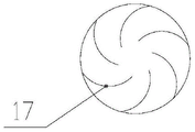
图2是本发明的导流盘的结构示意图。FIG. 2 is a schematic view of the structure of the guide plate of the present invention.
具体实施方式Detailed ways
下面结合本发明实施例中的附图以及具体实施例对本发明进行清楚地描述,在此处的描述仅仅用来解释本发明,但并不作为对本发明的限定。基于本发明中的实施例,本领域技术人员在没有做出创造性劳动前提下所获得的所有其他实施例,所做的任何修改、等同替换、改进等,均应包含在本发明的保护范围之内。The present invention will be clearly described below with reference to the accompanying drawings and specific embodiments in the embodiments of the present invention, and the descriptions herein are only used to explain the present invention, but are not intended to limit the present invention. Based on the embodiments of the present invention, all other embodiments obtained by those skilled in the art without creative work, any modifications, equivalent replacements, improvements, etc., should be included in the protection scope of the present invention. Inside.
实施例Example
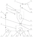
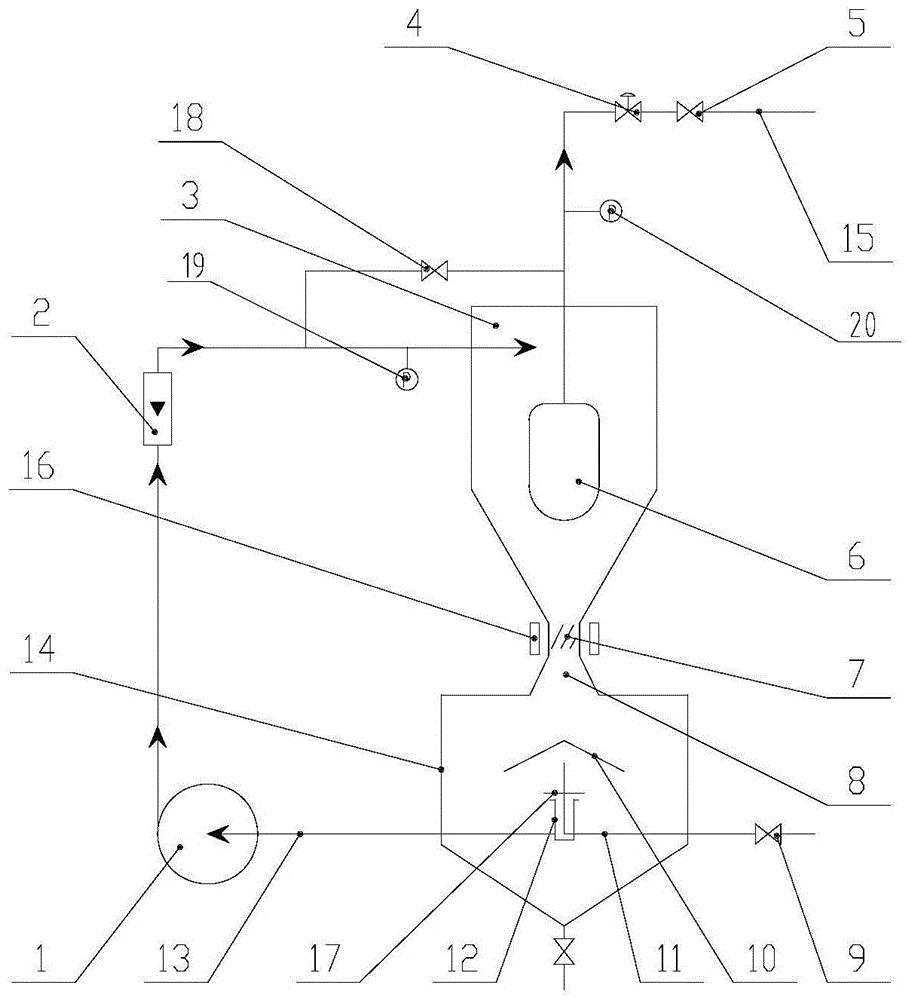
如图1~2所示,本发明提供了一种液体处理装置,包括混凝罐14和旋流器3,所述旋流器3通过拉瓦尔管8连接在混凝罐14上方,所述混凝罐14的下部采用倒锥形结构,且混凝罐14的两侧分别设有进液管11和出液管13,底部设有排污管,所述出液管13经出液泵1与旋流器3的进液口相连通,所述进液管11和排污管上分别设有进液阀9和排污阀,所述旋流器3顶部设有排液管15。所述混凝罐14内设有锥形隔离罩10、导流盘17和夹套12,所述锥形隔离罩10设于拉瓦尔管8的正下方,所述导流盘17设于锥形隔离罩10的正下方,所述夹套12设于导流盘17的正下方,所述进液管11穿入混凝罐14后从夹套12下部穿入并向上穿过导流盘17,且进液管11的出液口置于锥形隔离罩10的下方,所述出液管13的进液口与夹套12下部的排液孔相连通。锥形隔离罩10的作用为使液体在其上部形成附壁效应与空化效应,实现金属离子与液体的分离和液体中大分子有机物的离散,同时使锥形隔离罩10与导流盘17之间的区域形成真空区,使导流盘17上的液体更好地均匀分散开,使进入分散区的液体保持良好的分散性,有助于金属离子的沉降和分离,并有利于液体中的可溶性有机物中的有机大分子成分离散后的有效缔合。As shown in FIGS. 1 to 2 , the present invention provides a liquid treatment device, including a
所述旋流器3内设有过滤器6,所述过滤器6的内腔与排液管15相连通,过滤器6将液体中的颗粒杂质截留在过滤器6的内腔外,由于旋流器3内上部流体的离心运动在过滤器6的滤网周围形成一个负压区,方便实现滤网上颗粒杂质的自清理。所述拉瓦尔管8内设有螺旋导流槽7,用于对旋流回流出的液体进行螺旋引导与分散。述拉瓦尔管8外部设有磁激励管16,由于液体中离子的正负电荷特性不同,具有不同的牵引特征,且液体中的极性分子都具有对正负外在电荷的聚集特性,通过设置磁激励管16改变外在电磁方向,可改变液体中各类离子、极性分子的运动特征,从而促进分子的迁移碰撞、分离剪切,有利于更好的脱除液体中的金属离子。所述排液管15上沿排液方向依次设有第一压力表20、第一流量阀4和排液阀5,所述出液管13靠近旋流器3一端设有第二流量阀2和第二压力表19,所述排液管15与出液管13之间连通有回流管,所述回流管上设有回流阀18。出液管13上的第二压力表19用于监测旋流器3内的进液压力,排液管15上的第一压力表20用于监测排液时是否出现憋压现象,当出现憋压现象时,关闭排液管15上的排液阀5,打开回流管上的回流阀18,使液体回流到旋流器3内重新旋流。The
本发明的工作原理是,液体经进液管11进入混凝罐14内经初步混凝后,经出液管13上的出液泵1泵入旋流器3内进行旋流分离,合格的液体经排液管15外排,拉瓦尔管8起到流速增大器的作用,可增加旋流器3内液体的旋流效果,提高液体中金属离子的分离效率和大分子有机物的离散与缔合效率,同时保证液体向混凝罐14内的快速回流与再处理。The working principle of the present invention is that after the liquid enters the
以上已经描述了本发明的实施例,上述说明是示例性的,并非穷尽性的,并且也不限于所披露的实施例。在不偏离所说明实施例的范围和精神的情况下,对于本技术领域的普通技术人员来说许多修改和变更都是显而易见的。Embodiments of the present invention have been described above, and the foregoing description is exemplary, not exhaustive, and not limiting of the disclosed embodiments. Numerous modifications and variations will be apparent to those skilled in the art without departing from the scope and spirit of the described embodiments.
Claims (2)
Priority Applications (1)
| Application Number | Priority Date | Filing Date | Title |
|---|---|---|---|
| CN202011447608.0A CN112551663B (en) | 2020-12-09 | 2020-12-09 | a liquid handling device |
Applications Claiming Priority (1)
| Application Number | Priority Date | Filing Date | Title |
|---|---|---|---|
| CN202011447608.0A CN112551663B (en) | 2020-12-09 | 2020-12-09 | a liquid handling device |
Publications (2)
| Publication Number | Publication Date |
|---|---|
| CN112551663A CN112551663A (en) | 2021-03-26 |
| CN112551663B true CN112551663B (en) | 2022-09-09 |
Family
ID=75061890
Family Applications (1)
| Application Number | Title | Priority Date | Filing Date |
|---|---|---|---|
| CN202011447608.0A Active CN112551663B (en) | 2020-12-09 | 2020-12-09 | a liquid handling device |
Country Status (1)
| Country | Link |
|---|---|
| CN (1) | CN112551663B (en) |
Families Citing this family (1)
| Publication number | Priority date | Publication date | Assignee | Title |
|---|---|---|---|---|
| CN113768113A (en) * | 2021-09-14 | 2021-12-10 | 河南普乐泰食品科技有限公司 | Bone soup is with two-way steam explosion device of taking laval mouth type |
Family Cites Families (6)
| Publication number | Priority date | Publication date | Assignee | Title |
|---|---|---|---|---|
| NL96726C (en) * | 1957-12-20 | |||
| CN101811762A (en) * | 2010-03-23 | 2010-08-25 | 新疆科力新技术发展有限公司 | Coagulation and sedimentation testing device for oil field sewage |
| KR101425000B1 (en) * | 2012-08-22 | 2014-08-13 | 신해수 | Particle Separating Apparatus |
| CN107244724B (en) * | 2017-07-31 | 2023-09-15 | 中国中车股份有限公司 | Small coagulating sedimentation tank and method suitable for dispersing sewage drainage characteristics |
| CN209537204U (en) * | 2018-12-17 | 2019-10-25 | 淮阴工学院 | Magnetic loads water treatment facilities |
| CN109534553A (en) * | 2018-12-20 | 2019-03-29 | 陕煤集团神木张家峁矿业有限公司 | A kind of processing system and method for high suspended matter mine water |
-
2020
- 2020-12-09 CN CN202011447608.0A patent/CN112551663B/en active Active
Also Published As
| Publication number | Publication date |
|---|---|
| CN112551663A (en) | 2021-03-26 |
Similar Documents
| Publication | Publication Date | Title |
|---|---|---|
| CN203874919U (en) | Multistage oil-water cyclone separator | |
| CN108926878B (en) | Sewage treatment plant who deposits fast | |
| CN202289697U (en) | Water separation equipment | |
| CN101480636A (en) | Centrifugal subsidence mixed dirt remover | |
| CN111330317A (en) | A high-efficiency sewage sedimentation device and method | |
| CN112551663B (en) | a liquid handling device | |
| CN106345149A (en) | Concentrator flocculation reaction device | |
| CN206837644U (en) | A kind of novel sewage treatment unit | |
| CN105833569A (en) | Outer rotational flow limited flow channel membrane separator and method for demulsifying emulsion membrane through same | |
| CN205398327U (en) | Modularization oil -containing sewage treatment system | |
| CN204185331U (en) | A kind of air-flowing type water-and-oil separator | |
| CN206624871U (en) | Sand setting for anaerobic fermentation removes system | |
| CN104060978B (en) | A kind of multi-tube cyclone desander and desander method | |
| CN204865118U (en) | Cyclone -type sand precipitating pool | |
| CN105689154B (en) | A kind of black water flotation unit and technique | |
| CN209020595U (en) | An upper double outlet type three-phase cyclone separator | |
| CN107398116B (en) | Pipeline basket type cyclone filter | |
| CN105413238B (en) | A kind of oil water separator | |
| CN209442764U (en) | Oily wastewater suspended sludge filtering and purifying | |
| CN206927676U (en) | A kind of coal slime backflow coagulation-sedimentation equipment | |
| CN212282989U (en) | Oil-water separation device for molecular sieve synthetic slurry | |
| CN111252851A (en) | Vortex Sewage Treatment | |
| CN110204103A (en) | Suspension media layer filtration system based on hydraulic flow state stratification | |
| CN104998772A (en) | Cascaded cyclone separator | |
| CN206168097U (en) | Gas -solid separator |
Legal Events
| Date | Code | Title | Description |
|---|---|---|---|
| PB01 | Publication | ||
| PB01 | Publication | ||
| SE01 | Entry into force of request for substantive examination | ||
| SE01 | Entry into force of request for substantive examination | ||
| GR01 | Patent grant | ||
| GR01 | Patent grant |