CN112547254A - Food additive mixes all-in-one with distribution that has crushing structure - Google Patents
Food additive mixes all-in-one with distribution that has crushing structure Download PDFInfo
- Publication number
- CN112547254A CN112547254A CN202011290615.4A CN202011290615A CN112547254A CN 112547254 A CN112547254 A CN 112547254A CN 202011290615 A CN202011290615 A CN 202011290615A CN 112547254 A CN112547254 A CN 112547254A
- Authority
- CN
- China
- Prior art keywords
- cutting roller
- wall
- stirring
- centrifugal
- box
- Prior art date
- Legal status (The legal status is an assumption and is not a legal conclusion. Google has not performed a legal analysis and makes no representation as to the accuracy of the status listed.)
- Pending
Links
Images


Classifications
-
- B—PERFORMING OPERATIONS; TRANSPORTING
- B02—CRUSHING, PULVERISING, OR DISINTEGRATING; PREPARATORY TREATMENT OF GRAIN FOR MILLING
- B02C—CRUSHING, PULVERISING, OR DISINTEGRATING IN GENERAL; MILLING GRAIN
- B02C18/00—Disintegrating by knives or other cutting or tearing members which chop material into fragments
- B02C18/06—Disintegrating by knives or other cutting or tearing members which chop material into fragments with rotating knives
- B02C18/14—Disintegrating by knives or other cutting or tearing members which chop material into fragments with rotating knives within horizontal containers
- B02C18/142—Disintegrating by knives or other cutting or tearing members which chop material into fragments with rotating knives within horizontal containers with two or more inter-engaging rotatable cutter assemblies
-
- A—HUMAN NECESSITIES
- A23—FOODS OR FOODSTUFFS; TREATMENT THEREOF, NOT COVERED BY OTHER CLASSES
- A23P—SHAPING OR WORKING OF FOODSTUFFS, NOT FULLY COVERED BY A SINGLE OTHER SUBCLASS
- A23P30/00—Shaping or working of foodstuffs characterised by the process or apparatus
-
- B—PERFORMING OPERATIONS; TRANSPORTING
- B01—PHYSICAL OR CHEMICAL PROCESSES OR APPARATUS IN GENERAL
- B01F—MIXING, e.g. DISSOLVING, EMULSIFYING OR DISPERSING
- B01F33/00—Other mixers; Mixing plants; Combinations of mixers
- B01F33/80—Mixing plants; Combinations of mixers
- B01F33/83—Mixing plants specially adapted for mixing in combination with disintegrating operations
- B01F33/831—Devices with consecutive working receptacles, e.g. with two intermeshing tools in one of the receptacles
-
- B—PERFORMING OPERATIONS; TRANSPORTING
- B01—PHYSICAL OR CHEMICAL PROCESSES OR APPARATUS IN GENERAL
- B01F—MIXING, e.g. DISSOLVING, EMULSIFYING OR DISPERSING
- B01F35/00—Accessories for mixers; Auxiliary operations or auxiliary devices; Parts or details of general application
- B01F35/75—Discharge mechanisms
- B01F35/754—Discharge mechanisms characterised by the means for discharging the components from the mixer
- B01F35/7547—Discharge mechanisms characterised by the means for discharging the components from the mixer using valves, gates, orifices or openings
-
- B—PERFORMING OPERATIONS; TRANSPORTING
- B02—CRUSHING, PULVERISING, OR DISINTEGRATING; PREPARATORY TREATMENT OF GRAIN FOR MILLING
- B02C—CRUSHING, PULVERISING, OR DISINTEGRATING IN GENERAL; MILLING GRAIN
- B02C18/00—Disintegrating by knives or other cutting or tearing members which chop material into fragments
- B02C18/06—Disintegrating by knives or other cutting or tearing members which chop material into fragments with rotating knives
- B02C18/16—Details
-
- B—PERFORMING OPERATIONS; TRANSPORTING
- B02—CRUSHING, PULVERISING, OR DISINTEGRATING; PREPARATORY TREATMENT OF GRAIN FOR MILLING
- B02C—CRUSHING, PULVERISING, OR DISINTEGRATING IN GENERAL; MILLING GRAIN
- B02C23/00—Auxiliary methods or auxiliary devices or accessories specially adapted for crushing or disintegrating not provided for in preceding groups or not specially adapted to apparatus covered by a single preceding group
- B02C23/08—Separating or sorting of material, associated with crushing or disintegrating
- B02C23/14—Separating or sorting of material, associated with crushing or disintegrating with more than one separator
-
- B—PERFORMING OPERATIONS; TRANSPORTING
- B02—CRUSHING, PULVERISING, OR DISINTEGRATING; PREPARATORY TREATMENT OF GRAIN FOR MILLING
- B02C—CRUSHING, PULVERISING, OR DISINTEGRATING IN GENERAL; MILLING GRAIN
- B02C23/00—Auxiliary methods or auxiliary devices or accessories specially adapted for crushing or disintegrating not provided for in preceding groups or not specially adapted to apparatus covered by a single preceding group
- B02C23/08—Separating or sorting of material, associated with crushing or disintegrating
- B02C23/16—Separating or sorting of material, associated with crushing or disintegrating with separator defining termination of crushing or disintegrating zone, e.g. screen denying egress of oversize material
- B02C2023/165—Screen denying egress of oversize material
Abstract
The invention discloses a distributing and mixing integrated machine with a crushing structure for food additives, which comprises a feeding box, a centrifugal drum and a feeding pipe, wherein the feeding box is installed at the top of a machine body, a driving cutting roller and a driven cutting roller are installed on the inner wall of the front surface of the machine body through bearings, a stirring and mixing drum is installed on the inner wall of the machine body through a connecting rod, the centrifugal drum is installed inside the stirring and mixing drum, the feeding pipe is installed on the inner wall of one side of the machine body through a fixing ring, a liquid discharging box is fixed on the outer wall of one side of the machine body, a solid discharging box is fixed on the outer wall of the other side of the machine body, a heat dissipation ventilating plate is installed on the outer wall of the other side of the machine body, a machine door and a controller are installed on the. According to the invention, the device can lift the processed materials by arranging a series of assemblies, so that a worker does not need to bend down when taking the materials, and the materials are conveniently taken.
Description
Technical Field
The invention relates to the technical field of distribution and mixing integrated machines, in particular to a distribution and mixing integrated machine with a crushing structure for a food additive.
Background
The food additive is a natural substance or a chemical synthetic substance added into food for improving the quality, the color, the aroma and the taste of the food, preventing the food from being oxidized, rotted and deteriorated, and meeting the processing requirements during the production, processing, storage and the like of the food, and mostly exists in two forms of solid state and liquid state, so that the food additive needs to be mixed and distributed correspondingly to ensure the normal use of the food additive.
The existing distribution and mixing integrated machine has the defects that:
1. reference CN105855021A discloses a bentonite crushing processing equipment, "including the feeding structure, with the coarse crushing structure that the feeding structure links to each other and with the fine crushing structure that the coarse crushing structure links to each other, the coarse crushing structure includes the coarse crushing jar, the coarse crushing jar is provided with the feed inlet and is located the discharge gate of coarse crushing tank bottom, be provided with first crushing unit, set up in the coarse crushing jar and be in the screening part of first crushing unit below. The bentonite is crushed and ground by matching the coarse crushing and the fine grinding, the crushing effect is good by alternately circulating crushing and sieving, the bentonite crushed to reach the target particle size is timely collected, the crushing efficiency is improved, the crushing cost is reduced, the fine grinding structure adopts grinding areas with different particle sizes to gradually grind, the grinding efficiency is improved, compared with the bentonite crusher, the material taking position is lower, the stooping times of workers are increased when the materials are taken, and the bentonite is inconvenient to use;
2. the reference document CN108816377A discloses a wheat straw smashing and returning device, which comprises an access panel, a discharging structure, a feeding structure, a shell, a protection structure, a smashing structure, a transmission structure, a driving structure, an anti-blocking structure, a discharging channel, supporting legs and a junction box; a driving structure for driving and a transmission structure for transmission are arranged in the protective structure on the side wall of the shell; the transmission structure is connected with a feeding structure used for conveying materials in a matched manner, a crushing structure used for crushing and an anti-blocking structure used for blocking prevention in the shell, and the feeding structure is communicated with a discharging structure used for adding materials in the shell; the anti-blocking structure is arranged inside the discharging channel for discharging the wheat straws. The blanking structure is matched with the feeding structure for use, so that the wheat straws can be conveniently added into the device, the feeding is more convenient and quicker, the labor amount of the feeding is reduced, the crushing is more complete by matching the anti-blocking structure with the crushing structure for use, the crushing quality is improved, and compared with the device, the device is lack of a centrifugal screening function and insufficient in screening fineness;
3. the reference document CN106387973A discloses a food additive rapid modulation device for food production, which comprises a left frame, a first electric push rod, a support rod, a collection frame, a bottom plate, a right frame, a discharge hole, a first electric control valve, a second electric control valve, a fixed plate, a first support rod and the like; the top of the bottom plate is sequentially provided with a left frame, a first electric push rod, a support rod, a collecting frame and a right frame from left to right. The invention achieves the effects of uniform modulation, convenient operation and high modulation speed, the important function of the device is not only good modulation effect, but also improves the working efficiency, is beneficial to workers to conveniently use the device, and compared with the invention, the device can only process solid additives, thus causing the use range of the device to be limited.
Disclosure of Invention
The invention aims to provide a distributing and mixing all-in-one machine with a crushing structure for food additives, which is used for solving the problems in the background technology.
In order to achieve the purpose, the invention provides the following technical scheme: a distributing and mixing integrated machine with a crushing structure for food additives comprises a feeding box, a machine body, a liquid discharging box, a stirring and mixing cylinder, a centrifugal rotary cylinder and a feeding pipe, wherein the feeding box is installed at the top of the machine body, a driving cutting roller and a driven cutting roller are installed on the inner wall of the front side of the machine body through bearings, the driven cutting roller is positioned on one side of the driving cutting roller, the back sides of the driving cutting roller and the driven cutting roller extend out of the back wall of the machine body, a conveying belt is wound on the surfaces of the driving cutting roller and the driven cutting roller, a cutting motor is installed on the front side of the machine body through an installation table, the output end of the cutting motor extends into the interior of the machine body and is connected with the front side of the driving cutting roller, the stirring and mixing cylinder is installed on the inner wall of the machine body through a connecting rod, the centrifugal rotary cylinder is, and the conveying pipe is located one side of stirring mixing drum, be fixed with the liquid ejection of compact case through the triangular supports frame on the outer wall of one side of organism, be fixed with the solid ejection of compact case through the triangular supports frame on the opposite side outer wall of organism, install the heat dissipation ventilating board on the opposite side outer wall of organism, and the heat dissipation ventilating board is located the top of solid ejection of compact case, and the one end of heat dissipation ventilating board extends into the inside of organism, there are quick-witted door and controller in the front of organism through hinge movable mounting, and the controller is located the side top of quick-witted door, and the controller is located one side of cutting motor, and the controller passes through the wire and realizes electric connection with cutting motor, agitator motor, the inside electronic valve of conveying pipeline and rotating electrical machines.
Preferably, safety cover and self priming pump are installed to the top of liquid ejection of compact case, and the self priming pump is located the inside of safety cover, and the surface mounting of liquid ejection of compact case has the valve of a multiunit No. one.
Preferably, a plurality of groups of second valves are arranged on the surface of the solid discharging box.
Preferably, a rotating motor is installed at the top of the feeding pipe through a bearing, a screw rod is installed at the output end of the rotating motor, an inclined material guiding pipe is installed on the outer wall of one side of the feeding pipe, and one end of the material guiding pipe extends to the inside of the solid discharging box.
Preferably, a stirring rod is installed on the bottom wall of the interior of the centrifugal drum through a bearing, stirring blades different in length are installed on the surface of the stirring rod in a surrounding mode, a conical seat is installed at the bottom of the stirring rod in a penetrating mode, an embedding groove is formed in an inner wall interlayer of the centrifugal drum, an embedding mesh enclosure and a filtering mesh enclosure are connected to the inner wall interlayer of the centrifugal drum through the embedding groove, the filtering mesh enclosure is located on the outer side of the embedding mesh enclosure, and the mesh diameter of the filtering mesh enclosure is larger than the mesh diameter of the embedding mesh enclosure.
Preferably, agitator motor is installed to the bottom of stirring mixing cylinder, and the axostylus axostyle is installed to agitator motor's output, and the carousel is installed in running through at the top of axostylus axostyle, and the top of cutting the axostylus axostyle extends the inside that gets into centrifugal rotary drum and is connected with the bottom of puddler, and the conveying pipeline is installed to the bottom of stirring mixing cylinder, and the surface mounting of conveying pipeline has the electronic valve.
Preferably, the internally mounted of heat dissipation ventilating board has rack and filter screen, and the filter screen is located one side of rack, and the internally mounted of rack has the check valve.
Preferably, the inside of adding the material box is fixed with a plurality of feed inlets through the baffle, and the inside of feed inlet is the hourglass hopper-shaped of shrink, and the lid is installed in the top gomphosis of adding the material box.
Preferably, the top wall of the inside of the machine body is provided with a material guiding hopper, the top of the material guiding hopper is connected with the bottom of the material inlet, the inner wall of the machine body is provided with an inclined material guiding plate, and the bottom wall of the inside of the machine body is provided with a material collecting box.
Preferably, the working steps of the device are as follows:
s1, when the device is used for distributing and mixing food additives, the controller is used for starting the cutting motor and the stirring motor to prepare in advance, the closed feeding box is opened by the aid of the handle at the top of the box cover, different types of food additives are added into the device through the feeding hole, and the food additives can be introduced into the machine body through the material introducing hopper connected with the feeding hole;
s2, because the material guiding hopper is of a contraction structure from top to bottom, all solid food additives to be crushed entering the machine body can be intensively put right above the installation gap between the driving cutting roller and the driven cutting roller, so that the solid food additives vertically fall into the installation gap between the driving cutting roller and the driven cutting roller, and the cutting sheets staggered on the surfaces of the driving cutting roller and the driven cutting roller are utilized to perform corresponding crushing treatment;
s3, the solid food additive after being crushed is transmitted to the interior of the centrifugal drum through the material guide plate and supported by the torque provided by the stirring motor, the turntable can be used for driving the centrifugal drum and the stirring rod inside the centrifugal drum to rotate, so that when the solid food additive inside the centrifugal drum is stirred and mixed, when the additive is centrifugally screened, because the crushed additive has different grain sizes and different weights, when the crushed additive is subjected to the same rotating speed, the weight of the centrifugal drum is heavy due to the large particle size, so that the centrifugal drum is subjected to large centrifugal force and is easier to separate from the interior of the centrifugal drum, in the process, through double screening of the embedded mesh enclosure and the filter mesh enclosure, the additives meeting the particle size screening requirement can be ensured to be left in the centrifugal rotary drum, and then an electronic valve in the material conveying pipe is started, so that the screened additives enter the material collecting box;
s4, starting the rotating motor to drive the screw rod to rotate, driving the crushed and screened solid food additive in the material collecting box to gradually rise under the extrusion action of the surface helical blade, and sending the solid food additive into the solid discharging box through the material guiding pipe, so that a worker does not need to bend down when removing the material, and the use of the device is facilitated;
s5, when the device carries out the mix distribution of liquid food additive, after adding the raw materials through the feed inlet, only need start agitator motor, after stirring and mixing and centrifugal operation to the inside liquid that gets into the stirring mixing drum, start the inside electronic valve of conveying pipeline, make it get into and start the self priming pump after the collecting box is inside, pump its inside to liquid ejection of compact case, can realize taking of material through a valve, avoided bowing to get the material, made things convenient for the use of device.
Compared with the prior art, the invention has the beneficial effects that:
1. according to the invention, the liquid discharging box, the feeding pipe and the solid discharging box are arranged, after the self-sucking pump is started, the liquid which is mixed and stirred inside the aggregate box can be pumped into the liquid discharging box, a worker can open the first valve to realize multi-station material taking, the material taking efficiency is improved, and the liquid at the bottom of the machine body can be lifted to a certain height through the pumping of the self-sucking pump, so that the worker can take materials without bending down when taking materials, the material taking work of the worker is facilitated, the solid additive inside the aggregate box can be conveyed into the solid discharging box through the feeding pipe, the ascending transfer of the material taking position is realized, and the bending times of the worker during material taking are further reduced.
2. The invention can drive the stirring blade to rotate by being provided with the centrifugal rotary drum and driven by the stirring rod, so that additives in the centrifugal rotary drum are mixed and stirred, the solid food additives in the centrifugal rotary drum are stirred, mixed and treated, and simultaneously, the solid food additives are centrifugally screened, and the additives which meet the particle size screening requirement can be ensured to be left in the centrifugal rotary drum through double screening of the embedded mesh enclosure and the filter mesh enclosure in the process, and then an electronic valve in the material conveying pipe is started, so that the screened additives enter the material collecting box, and the embedded mesh enclosure and the filter mesh enclosure are installed in an embedded manner, so that the disassembly and the cleaning are convenient, and the arrangement of the frustum seat can convey the additives accumulated on the surface of the frustum seat to the top of the material conveying pipe, and the materials are prevented from being accumulated in the centrifugal rotary drum.
3. The invention can operate solid and liquid food additives, so that the range of processing objects of the device is enlarged, and the solid crushing operation can be carried out while the mixing operation of the liquid additives can be synchronously carried out.
Drawings
FIG. 1 is a schematic view of the overall structure of the present invention;
FIG. 2 is a schematic view of the internal structure of the present invention;
FIG. 3 is a schematic view of the feed inlet configuration of the present invention;
FIG. 4 is a schematic view of a top-down mounting structure of the driving cutting roller and the driven cutting roller of the present invention;
FIG. 5 is a schematic view of the structure at A in FIG. 2 according to the present invention;
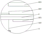
FIG. 6 is a schematic view of the construction of the centrifuge bowl of the present invention;
FIG. 7 is a schematic top view of the centrifuge bowl of the present invention;
fig. 8 is a partial structural view of the heat dissipation and ventilation board of the present invention.
In the figure: 1. a feeding box; 101. a feed inlet; 102. a box cover; 2. a body; 201. a material guiding hopper; 202. a material guide plate; 203. a material collecting box; 3. an active cutting roller; 301. cutting the motor; 302. a conveyor belt; 303. a driven cutting roller; 4. a liquid discharging box; 401. a self-priming pump; 402. a first valve; 403. a protective cover; 5. a stirring and mixing cylinder; 501. a stirring motor; 502. a delivery pipe; 503. a turntable; 6. a centrifugal drum; 601. a stirring rod; 602. a conical pedestal; 603. stirring the page; 604. embedding a mesh enclosure; 605. a filtering net cover; 7. a feed pipe; 701. a screw rod; 702. a rotating electric machine; 703. a material guiding pipe; 8. a heat dissipating and ventilating plate; 801. a net frame; 802. filtering with a screen; 9. a solid discharging box; 901. a second valve; 10. a machine door; 11. and a controller.
Detailed Description
The technical solutions in the embodiments of the present invention will be clearly and completely described below with reference to the drawings in the embodiments of the present invention, and it is obvious that the described embodiments are only a part of the embodiments of the present invention, and not all of the embodiments. All other embodiments, which can be derived by a person skilled in the art from the embodiments given herein without making any creative effort, shall fall within the protection scope of the present invention.
Referring to fig. 1-8, an embodiment of the present invention: a distributing and mixing integrated machine with a crushing structure for food additives comprises a feeding box 1, a machine body 2, a liquid discharging box 4, a stirring and mixing cylinder 5, a centrifugal rotary drum 6 and a feeding pipe 7, wherein the feeding box 1 is installed at the top of the machine body 2, the machine body 2 can provide a relatively closed space for the device to perform corresponding additive distributing and mixing work, interference of an external environment is prevented, the feeding box 1 provides an inlet for workers to put additives into the machine body 2, a driving cutting roller 3 and a driven cutting roller 303 are installed on the inner wall of the front surface of the machine body 2 through bearings, the driven cutting roller 303 is positioned on one side of the driving cutting roller 3, the back surfaces of the driving cutting roller 3 and the driven cutting roller 303 extend out of the back wall of the machine body 2, the driving cutting roller 3 and the driven cutting roller 303 can enable cutting blades with staggered surfaces to crush solid food additives to be crushed through rotation, the surfaces of the driving cutting roller 3 and the driven cutting roller 303 are wound with a conveying belt 302, the driven cutting roller 303 can be driven to synchronously rotate when the driving cutting roller 3 rotates through the conveying belt effect, the auxiliary device finishes corresponding crushing work, the front surface of the machine body 2 is provided with a cutting motor 301 through a mounting table, the output end of the cutting motor 301 extends into the interior of the machine body 2 to be connected with the front surface of the driving cutting roller 3, electric energy can be converted into mechanical energy, further, power support is provided for the rotation of the driving cutting roller 3, the inner wall of the machine body 2 is provided with a stirring mixing drum 5 through a connecting rod, a position space is provided for the installation of the centrifugal mixing drum 6, the centrifugal mixing drum 6 is installed inside the stirring mixing drum 5, the centrifugal screening operation can be performed on the additives inside the stirring mixing drum through the rotating effect, the fine degree of the device processing is improved, a feeding pipe 7 is installed on the inner, the feeding pipe 7 is positioned at one side of the stirring and mixing cylinder 5 and can convey the solid additives in the aggregate box 203 to the inside of the solid discharging box 9 to realize the ascending and transferring of the material taking position and further reduce the stooping times of workers during material taking, the liquid discharging box 4 is fixed on the outer wall of one side of the machine body 2 through a triangular support frame and can store the liquid additives after mixed treatment for the convenience of the workers to take, the solid discharging box 9 is fixed on the outer wall of the other side of the machine body 2 through the triangular support frame and can store the solid additives after crushing and centrifugal screening treatment for the convenience of the workers to take, the radiating and ventilating plate 8 is arranged on the outer wall of the other side of the machine body 2, the radiating and ventilating plate 8 is positioned above the solid discharging box 9, one end of the radiating and ventilating plate 8 extends into the interior of the machine body 2, and can facilitate the heat exchange between the heat generated during working and the exterior of, thereby protect the life of motor, there are door 10 and controller 11 in the front of organism 2 through hinge movable mounting, and controller 11 is located the side top of door 10, controller 11 is located one side of cutting motor 301, controller 11 passes through wire and cutting motor 301, agitator motor 501, the inside electronic valve of conveying pipeline 502 and rotating electrical machines 702 realize electric connection, door 10 can be opened, make things convenient for the staff to clear up stirring mixing drum 5 and centrifugal rotor 6 inside organism 2, and controller 11 is through the rotation of surface control button, can control cutting motor 301, agitator motor 501, the operating condition of the inside electronic valve of conveying pipeline 502 and rotating electrical machines 702, the operation of device has been made things convenient for.
The top of the liquid discharging box 4 is provided with a protective cover 403 and a self-sucking pump 401, the self-sucking pump 401 is positioned inside the protective cover 403, the surface of the liquid discharging box 4 is provided with a plurality of groups of first valves 402, the input end of the self-sucking pump 401 is connected with a water pipe, one end of the water pipe extends into the material collecting box 203 inside the machine body 2, the output end of the water pipe is connected with a hose, and one end of the hose extends into the liquid discharging box 4, so that after the self-sucking pump 401 is started, the liquid mixed and stirred inside the material collecting box 203 can be pumped into the liquid discharging box 4, a worker can realize multi-station material taking by opening the first valve 402, the material taking efficiency is improved, and through the pumping of the self-sucking pump 401, the liquid at the bottom of the machine body 2 can be lifted to a certain height, so that the worker can realize material taking without bending down, the protective cover 403 provides protection to the self-primer pump 401, thereby extending its useful life.
The surface mounting of solid ejection of compact case 9 has No. two valves 901 of multiunit, and the staff opens No. two valves 901 and can realize that the multistation is got the material, has improved and has got material efficiency.
Rotating electrical machines 702 is installed through the bearing at the top of conveying pipe 7, hob 701 is installed to rotating electrical machines 702's output, the material pipe 703 that draws of slope is installed to one side outer wall of conveying pipe 7, and the one end that draws material pipe 703 extends to the inside of solid ejection of compact case 9, start rotating electrical machines 702, it rotates to drive hob 701, utilize its surperficial helical blade's squeezing action to drive the inside process of collection magazine 203 and smash, the solid food additive of screening process can rise gradually, and send into the inside of solid ejection of compact case 9 through drawing material pipe 703, thereby make the staff can not necessarily bow the operation when getting the material, the use of device has been made things convenient for.
The bottom wall of the interior of the centrifugal rotary drum 6 is provided with a stirring rod 601 through a bearing, the surface of the stirring rod 601 is provided with stirring blades 603 with different lengths in a surrounding manner, the bottom of the stirring rod 601 is provided with a conical pedestal 602 in a penetrating manner, an embedding groove is arranged in an interlayer of the inner wall of the centrifugal rotary drum 6, the interlayer of the inner wall of the centrifugal rotary drum 6 is connected with an embedding mesh enclosure 604 and a filter mesh enclosure 605 through the embedding groove, the filter mesh enclosure 605 is positioned at the outer side of the embedding mesh enclosure 604, the mesh diameter of the filter mesh enclosure 605 is larger than that of the embedding mesh enclosure 604, the centrifugal rotary drum 6 and the stirring rod 601 inside the centrifugal rotary drum can be driven to rotate by a rotary disc 503 through the torque support provided by a stirring motor 501, the stirring blades 603 can be driven to rotate through the stirring rod 601, so that the additives in the centrifugal rotary drum 6 are, the centrifugal screening operation is carried out on the additive, the particle size of the crushed additive is different, the weight is unequal, when the rotating speed of the same size is received, the weight is large due to the large particle size, the centrifugal acting force is large, the additive is more easily separated from the inside of the centrifugal rotary drum 6, the embedded mesh enclosure 604 and the filter mesh enclosure 605 are subjected to double screening in the process, the additive meeting the particle size screening requirement can be ensured to be remained in the centrifugal rotary drum 6, then an electronic valve in the conveying pipe 502 is started, the screened additive enters the material collecting box 203, the embedded mesh enclosure 604 and the filter mesh enclosure 605 are installed in an embedded mode, the disassembly and the cleaning are convenient, the conical pedestal 602 is arranged, the additive accumulated on the surface of the additive can be conveyed to the top of the conveying pipe 502, and the material is prevented from being accumulated in the centrifugal rotary drum 6.
The internally mounted of heat dissipation ventilating board 8 has rack 801 and filter screen 802, filter screen 802 is located one side of rack 801, and the internally mounted of rack 801 has the check valve, filter screen 802 can make things convenient for 2 inside and outside heat exchange that carry on of organism, and can block the inside that outside dust got into organism 2, the health nature of protection device course of working, rack 801 is through inside check valve, can avoid outside gas to get into inside organism 2, avoid inside the harmful gas access device in the air, guarantee the health and safety of device processing.
Add the inside of feed box 1 and be fixed with a plurality of feed inlets 101 through the baffle, the inside of feed inlet 101 is the hourglass hopper-shaped of shrink, adds the top gomphosis of feed box 1 and installs lid 102, can be to the inside additive raw materials of puting in of organism 2 through feed inlet 101, and lid 102 then can seal the processing with adding feed box 1, the inside health of protection device.
The inside roof of organism 2 is installed and is drawn hopper 201, the top that draws hopper 201 is connected with the bottom of feed inlet 101, the stock guide 202 of slope is installed to the inner wall of organism 2, the magazine 203 of gathering is installed to the inside diapire of organism 2, can convey the additive raw materials in the feed inlet 101 to initiative cutting roller 3 and driven cutting roller 303 directly over through drawing hopper 201, make things convenient for the device to carry out corresponding crushing operation, the stock guide 202 can be with falling on the inside of the additive raw materials water conservancy diversion to centrifugal rotor 6 on the organism 2 inner wall, the magazine 203 of gathering materials can be stored the additive material after centrifugal screening is handled, so that carry out subsequent material and rise the transfer operation.
The working steps of the device are as follows:
s1, when the device is used for distributing and mixing food additives, the controller 11 is firstly utilized to start the cutting motor 301 and the stirring motor 501 to prepare in advance, then the handle at the top of the box cover 102 is utilized to open the closed feeding box 1, then different types of food additives are added into the device through the feeding hole 101, and the food additives can be introduced into the machine body 2 through the material introducing hopper 201 connected with the feeding hole 101;
s2, because the material guiding hopper 201 is of a contraction structure from top to bottom, all solid food additives to be crushed entering the machine body 2 can be intensively put right above the installation gap between the driving cutting roller 3 and the driven cutting roller 303, so that the solid food additives vertically fall into the installation gap between the driving cutting roller 3 and the driven cutting roller 303, and the cutting sheets staggered on the surfaces of the driving cutting roller 3 and the driven cutting roller 303 are utilized to perform corresponding crushing treatment;
s3, the crushed solid food additive is conveyed to the interior of the centrifugal drum 6 through the material guiding plate 202, supported by the torque provided by the stirring motor 501, the turntable 503 can be used to drive the centrifugal drum 6 and the stirring rod 601 inside the centrifugal drum to rotate, so that while the solid food additive inside the centrifugal drum 6 is stirred and mixed, when the additive is centrifugally screened, because the crushed additive has different grain sizes and different weights, when the crushed additive is subjected to the same rotating speed, the weight of the centrifugal rotor is heavy due to the large particle size, so that the centrifugal rotor is subjected to large centrifugal force and is easier to separate from the interior of the centrifugal rotor 6, in the process, through the double screening of the embedded mesh enclosure 604 and the filter mesh enclosure 605, the additives meeting the particle size screening requirement are remained in the centrifugal rotary drum 6, and then the electronic valve in the conveying pipe 502 is started, so that the screened additives enter the material collecting box 203;
s4, starting the rotating motor 702 to drive the screw rod 701 to rotate, driving the crushed and screened solid food additives in the material collecting box 203 to gradually rise under the extrusion action of the surface helical blade of the rotating motor, and sending the solid food additives into the solid discharging box 9 through the material guiding pipe 703, so that a worker does not need to bend down when removing materials, and the use of the device is facilitated;
s5, when the device carries out the liquid food additive mixture when distributing, after adding the raw materials through feed inlet 101, only need start agitator motor 501, stir the mixture and centrifugal operation back to the inside liquid that gets into stirring mixing drum 5, start the inside electronic valve of conveying pipeline 502, make it get into and start self priming pump 401 after collecting magazine 203 is inside, pump its inside to liquid ejection of compact case 4, can realize taking of material through valve 402, avoided bowing to get the material, the use of device has been made things convenient for.
The working principle is as follows: when the device is used for distributing and mixing food additives, the controller 11 is firstly utilized to start the cutting motor 301 and the stirring motor 501 to prepare in advance, then the handle at the top of the box cover 102 is utilized to open the closed feeding box 1, then different types of food additives are added into the device through the feeding hole 101, the food additives can be introduced into the machine body 2 through the material guiding hopper 201 connected with the feeding hole 101, the material guiding hopper 201 is of a contraction structure from top to bottom, so that the solid food additives to be crushed entering the machine body 2 can be all intensively put into the right upper part of the installation gap between the driving cutting roller 3 and the driven cutting roller 303, and then the solid food additives vertically fall into the installation gap between the driving cutting roller 3 and the driven cutting roller 303, and the cutting sheets arranged on the surfaces of the driving cutting roller 3 and the driven cutting roller 303 are utilized to carry out corresponding staggered crushing treatment, the crushed solid food additive is conveyed to the inside of the centrifugal rotary drum 6 through the material guide plate 202, supported by the torque provided by the stirring motor 501, the rotary disc 503 can be used for driving the centrifugal rotary drum 6 and the stirring rod 601 inside the centrifugal rotary drum 6 to rotate, the solid food additive inside the centrifugal rotary drum 6 can be stirred, mixed and processed, and simultaneously, the centrifugal screening operation is carried out on the solid food additive, because the crushed additive has different grain diameters and unequal weights, when the solid food additive is subjected to the same rotating speed, the weight of the crushed additive is large due to the large grain diameter, the centrifugal acting force is large, the crushed additive is more easily separated from the inside of the centrifugal rotary drum 6, the additive meeting the grain diameter screening requirement can be ensured to be remained inside the centrifugal rotary drum 6 through the double screening of the embedded mesh enclosure 604 and the filter mesh enclosure 605, then, the electronic valve inside the material conveying pipe 502 is started, so that the screened additive enters the, at this moment, the solid food additive is in the material collecting box 203, the rotating motor 702 is started to drive the screw rod 701 to rotate, the extrusion effect of the helical blade on the surface of the screw rod drives the solid food additive which is crushed and screened in the material collecting box 203 to gradually rise and be sent into the solid discharging box 9 through the material guiding pipe 703, so that a worker does not need to bend down when getting the material, the use of the device is facilitated, when the device mixes and distributes the liquid food additive, after the raw material is added through the material inlet 101, the stirring motor 501 is only needed to be started, after the liquid entering the stirring mixing cylinder 5 is stirred, mixed and centrifugally operated, the electronic valve in the material conveying pipe 502 is started, the self-priming pump 401 is started after the liquid enters the material collecting box 203, the liquid is pumped into the liquid discharging box 4, and the taking of the material can be realized through the valve 402, the material taking by bending is avoided, and the use of the device is facilitated.
It will be evident to those skilled in the art that the invention is not limited to the details of the foregoing illustrative embodiments, and that the present invention may be embodied in other specific forms without departing from the spirit or essential attributes thereof. The present embodiments are therefore to be considered in all respects as illustrative and not restrictive, the scope of the invention being indicated by the appended claims rather than by the foregoing description, and all changes which come within the meaning and range of equivalency of the claims are therefore intended to be embraced therein. Any reference sign in a claim should not be construed as limiting the claim concerned.
Claims (10)
1. The utility model provides a food additive is with distribution mixing all-in-one that has crushing structure, includes reinforced box (1), organism (2), liquid ejection of compact case (4), stirring mixing drum (5), centrifugal rotary drum (6) and conveying pipe (7), its characterized in that: the top of organism (2) is installed and is added feed box (1), initiative cutting roller (3) and driven cutting roller (303) are installed through the bearing to the front inner wall of organism (2), and driven cutting roller (303) are located one side of initiative cutting roller (3), and the back of initiative cutting roller (3) and driven cutting roller (303) extends the back wall of organism (2), the surface winding of initiative cutting roller (3) and driven cutting roller (303) has conveyer (302), cutting motor (301) is installed through the mount table in the front of organism (2), and the output of cutting motor (301) extends the inside that gets into organism (2) and the front of initiative cutting roller (3) is connected, stirring mixing drum (5) is installed through the connecting rod to the inner wall of organism (2), the internally mounted of stirring mixing drum (5) has centrifugal rotary drum (6), install conveying pipe (7) through solid fixed ring on the one side inner wall of organism (2), and conveying pipe (7) are located one side of stirring mixing drum (5), be fixed with liquid ejection of compact case (4) through the triangular supports frame on the one side outer wall of organism (2), be fixed with solid ejection of compact case (9) through the triangular supports frame on the opposite side outer wall of organism (2), install heat dissipation ventilating board (8) on the opposite side outer wall of organism (2), and heat dissipation ventilating board (8) are located the top of solid ejection of compact case (9), and the inside of organism (2) is extended into to the one end of heat dissipation ventilating board (8), there are door (10) and controller (11) in the front of organism (2) through hinge movable mounting, and controller (11) are located the side top of door (10), and controller (11) are located one side of cutting motor (301), and controller (11) are through wire and cutting motor (301), The stirring motor (501), the electronic valve in the material conveying pipe (502) and the rotating motor (702) are electrically connected.
2. The integrated machine with crushing structure for food additive according to claim 1, wherein: protection cover (403) and self priming pump (401) are installed to the top of liquid ejection of compact case (4), and self priming pump (401) are located the inside of protection cover (403), and the surface mounting of liquid ejection of compact case (4) has a multiunit valve (402).
3. The integrated machine with crushing structure for food additive according to claim 1, wherein: and a plurality of groups of second valves (901) are arranged on the surface of the solid discharging box (9).
4. The integrated machine with crushing structure for food additive according to claim 1, wherein: the top of the feeding pipe (7) is provided with a rotating motor (702) through a bearing, the output end of the rotating motor (702) is provided with a screw rod (701), the outer wall of one side of the feeding pipe (7) is provided with an inclined material guiding pipe (703), and one end of the material guiding pipe (703) extends to the inside of the solid discharging box (9).
5. The integrated machine with crushing structure for food additive according to claim 1, wherein: the stirring rod (601) is installed through the bearing to the inside diapire of centrifugal rotary drum (6), stirring page (603) that the length is different is installed around on the surface of stirring rod (601), conical seat (602) are installed in the bottom of stirring rod (601) through running through, be equipped with the gomphosis groove in the inner wall intermediate layer of centrifugal rotary drum (6), be connected with gomphosis screen panel (604) and filter screen panel (605) through the gomphosis groove in the inner wall intermediate layer of centrifugal rotary drum (6), and filter screen panel (605) are located the outside of gomphosis screen panel (604), the net footpath of filter screen panel (605) is greater than the net footpath of gomphosis screen panel (604.
6. The integrated machine with crushing structure for food additive according to claim 1, wherein: stirring motor (501) is installed to the bottom of stirring mixing drum (5), and the axostylus axostyle is installed to the output of stirring motor (501), and carousel (503) are installed to the top of axostylus axostyle running through, and the top of cutting the axostylus axostyle extends the inside that gets into centrifugal rotor (6) and is connected with the bottom of puddler (601), and conveying pipeline (502) are installed to the bottom of stirring mixing drum (5), and the surface mounting of conveying pipeline (502) has the electronic valve.
7. The integrated machine with crushing structure for food additive according to claim 1, wherein: the internally mounted of heat dissipation ventilating board (8) has rack (801) and filter screen (802), and filter screen (802) are located one side of rack (801), and the internally mounted of rack (801) has the check valve.
8. The integrated machine with crushing structure for food additive according to claim 1, wherein: the inside of adding feed box (1) is fixed with a plurality of feed inlets (101) through the baffle, and the inside of feed inlet (101) is the hourglass hopper-shaped of shrink, and lid (102) are installed in the top gomphosis of adding feed box (1).
9. The integrated machine with crushing structure for food additive according to claim 1, wherein: the material guiding hopper (201) is installed on the inside top wall of the machine body (2), the top of the material guiding hopper (201) is connected with the bottom of the feeding hole (101), the inclined material guiding plate (202) is installed on the inner wall of the machine body (2), and the material collecting box (203) is installed on the inside bottom wall of the machine body (2).
10. A dispensing and mixing machine with a comminution structure for food additives according to claims 1-9, characterized in that it operates as follows:
s1, when the device is used for distributing and mixing food additives, the controller (11) is used for starting the cutting motor (301) and the stirring motor (501) to prepare in advance, the closed feeding box (1) is opened by the handle at the top of the box cover (102), different types of food additives are added into the device through the feeding hole (101), and the food additives can be introduced into the machine body (2) through the introducing hopper (201) connected with the feeding hole (101);
s2, because the material guiding hopper (201) is of a contraction structure from top to bottom, all solid food additives to be crushed entering the machine body (2) can be intensively put into the position right above the installation gap between the driving cutting roller (3) and the driven cutting roller (303), so that the solid food additives vertically fall into the installation gap between the driving cutting roller (3) and the driven cutting roller (303), and the cutting pieces arranged on the surfaces of the driving cutting roller (3) and the driven cutting roller (303) in a staggered mode are used for carrying out corresponding crushing treatment;
s3, the crushed solid food additive is transmitted to the inside of the centrifugal rotary drum (6) through the material guide plate (202), supported by the torque provided by the stirring motor (501), the rotary disc (503) can be used to drive the centrifugal rotary drum (6) and the stirring rod (601) inside the centrifugal rotary drum to rotate, the solid food additive inside the centrifugal rotary drum (6) can be stirred, mixed and processed, and simultaneously, the centrifugal screening operation is carried out on the solid food additive, because the particle diameters of the crushed additive are different and the weight is unequal, when the solid food additive is subjected to the rotating speed with the same size, the weight is large because the particle diameter is large, the centrifugal acting force is also large, the solid food additive is more easily separated from the inside of the centrifugal rotary drum (6), and in the process, the additive meeting the particle diameter screening requirement is remained inside the centrifugal rotary drum (6) through the double screening of the embedded mesh enclosure (604) and the filter mesh enclosure (605, then starting an electronic valve inside the material conveying pipe (502) to enable the screened additive to enter the material collecting box (203);
s4, starting the rotating motor (702) to drive the screw rod (701) to rotate, driving the solid food additives subjected to crushing and screening treatment in the material collection box (203) to gradually rise under the extrusion action of the surface helical blades of the rotating motor, and sending the solid food additives into the solid discharge box (9) through the material guide pipe (703), so that a worker can remove materials without bending down, and the use of the device is facilitated;
s5, when the device carries out the mixed distribution of liquid food additive, after adding the raw materials through feed inlet (101), only need start agitator motor (501), stir the liquid that gets into stirring mixing drum (5) inside and mix and centrifugal operation after, start the inside electronic valve of conveying pipeline (502), make it get into collection magazine (203) inside back start self priming pump (401), pump its inside to liquid ejection of compact case (4), can realize taking of material through valve (402), avoided bowing to get the material, the use of device has been made things convenient for.
Priority Applications (1)
| Application Number | Priority Date | Filing Date | Title |
|---|---|---|---|
| CN202011290615.4A CN112547254A (en) | 2020-11-18 | 2020-11-18 | Food additive mixes all-in-one with distribution that has crushing structure |
Applications Claiming Priority (1)
| Application Number | Priority Date | Filing Date | Title |
|---|---|---|---|
| CN202011290615.4A CN112547254A (en) | 2020-11-18 | 2020-11-18 | Food additive mixes all-in-one with distribution that has crushing structure |
Publications (1)
| Publication Number | Publication Date |
|---|---|
| CN112547254A true CN112547254A (en) | 2021-03-26 |
Family
ID=75044289
Family Applications (1)
| Application Number | Title | Priority Date | Filing Date |
|---|---|---|---|
| CN202011290615.4A Pending CN112547254A (en) | 2020-11-18 | 2020-11-18 | Food additive mixes all-in-one with distribution that has crushing structure |
Country Status (1)
| Country | Link |
|---|---|
| CN (1) | CN112547254A (en) |
Cited By (1)
| Publication number | Priority date | Publication date | Assignee | Title |
|---|---|---|---|---|
| CN115351034A (en) * | 2022-08-18 | 2022-11-18 | 伍兆丰 | Agricultural straw treatment and recycling device with mulching film separation function |
Citations (10)
| Publication number | Priority date | Publication date | Assignee | Title |
|---|---|---|---|---|
| CN204656616U (en) * | 2015-04-14 | 2015-09-23 | 成都丰亚建材有限公司 | Construction material treating apparatus |
| CN205305808U (en) * | 2015-12-23 | 2016-06-15 | 浙江易拓园林开发有限公司 | Portable liquid spraying insecticidal system that supplies of municipal garden afforestation |
| CN206356049U (en) * | 2016-11-05 | 2017-07-28 | 大同市蔡氏矿纤维制造有限公司 | A kind of gangue comminuting dasher |
| CN207430387U (en) * | 2017-08-29 | 2018-06-01 | 金海燕 | A kind of circulating birds solid feed reducing mechanism |
| CN209034571U (en) * | 2018-07-16 | 2019-06-28 | 石城县群鑫生态发展有限公司 | A kind of oil residue separator device for being used to squeeze peanut oil convenient for collecting the dregs of fat |
| CN209901382U (en) * | 2019-04-12 | 2020-01-07 | 河南丹圣源农业开发有限公司 | Fruit breaker of pomegranate production and processing |
| CN110813996A (en) * | 2019-11-23 | 2020-02-21 | 衡阳恰美纸塑制品有限公司 | Waste recovery device is used in paper plastic products production |
| CN110947755A (en) * | 2019-12-30 | 2020-04-03 | 山东捷利尔生物工程科技有限公司 | Soil remediation device |
| CN210333564U (en) * | 2019-05-29 | 2020-04-17 | 安俊颖 | Metal raw material deoiling machine |
| CN211169961U (en) * | 2019-10-09 | 2020-08-04 | 四川绿艺华福石化科技有限公司 | Centrifugal dehydrator for treating waste emulsion |
-
2020
- 2020-11-18 CN CN202011290615.4A patent/CN112547254A/en active Pending
Patent Citations (10)
| Publication number | Priority date | Publication date | Assignee | Title |
|---|---|---|---|---|
| CN204656616U (en) * | 2015-04-14 | 2015-09-23 | 成都丰亚建材有限公司 | Construction material treating apparatus |
| CN205305808U (en) * | 2015-12-23 | 2016-06-15 | 浙江易拓园林开发有限公司 | Portable liquid spraying insecticidal system that supplies of municipal garden afforestation |
| CN206356049U (en) * | 2016-11-05 | 2017-07-28 | 大同市蔡氏矿纤维制造有限公司 | A kind of gangue comminuting dasher |
| CN207430387U (en) * | 2017-08-29 | 2018-06-01 | 金海燕 | A kind of circulating birds solid feed reducing mechanism |
| CN209034571U (en) * | 2018-07-16 | 2019-06-28 | 石城县群鑫生态发展有限公司 | A kind of oil residue separator device for being used to squeeze peanut oil convenient for collecting the dregs of fat |
| CN209901382U (en) * | 2019-04-12 | 2020-01-07 | 河南丹圣源农业开发有限公司 | Fruit breaker of pomegranate production and processing |
| CN210333564U (en) * | 2019-05-29 | 2020-04-17 | 安俊颖 | Metal raw material deoiling machine |
| CN211169961U (en) * | 2019-10-09 | 2020-08-04 | 四川绿艺华福石化科技有限公司 | Centrifugal dehydrator for treating waste emulsion |
| CN110813996A (en) * | 2019-11-23 | 2020-02-21 | 衡阳恰美纸塑制品有限公司 | Waste recovery device is used in paper plastic products production |
| CN110947755A (en) * | 2019-12-30 | 2020-04-03 | 山东捷利尔生物工程科技有限公司 | Soil remediation device |
Cited By (1)
| Publication number | Priority date | Publication date | Assignee | Title |
|---|---|---|---|---|
| CN115351034A (en) * | 2022-08-18 | 2022-11-18 | 伍兆丰 | Agricultural straw treatment and recycling device with mulching film separation function |
Similar Documents
| Publication | Publication Date | Title |
|---|---|---|
| CN111908957A (en) | System for kitchen garbage preparation fertilizer | |
| CN107983468A (en) | A kind of ore treatment disintegrating apparatus for grinding cut type | |
| CN210935327U (en) | Civil engineering construction waste treatment device | |
| CN206262402U (en) | Fodder mixing machine | |
| CN112547254A (en) | Food additive mixes all-in-one with distribution that has crushing structure | |
| CN211358950U (en) | Petroleum refining waste treatment device | |
| CN111567240A (en) | Agricultural straw reducing mechanism | |
| CN208990958U (en) | A kind of building waste grinding device | |
| KR20140036486A (en) | Apparatus for vegetable garbage | |
| CN111715124A (en) | Compounding device is used in tombarthite alloy production | |
| CN111672397A (en) | Automatic mixing treatment equipment and treatment method for cereal and fruit comprehensive oatmeal raw materials | |
| CN105170289B (en) | A kind of integrated form break process method of industrial wood rubbish | |
| CN215996940U (en) | Natural plant gel draws uses homogeneity broken wall device | |
| CN218742212U (en) | Split type circulation selection powder machine convenient to overhaul | |
| CN219187094U (en) | Mica rubbing crusher unloading screening mechanism | |
| CN217910793U (en) | Soft particle fermented feed processing unit | |
| CN215541513U (en) | Blade type flour mill | |
| CN215075413U (en) | Material discharging path variable type material discharging mechanism for grass smashing processing | |
| CN109275922A (en) | A kind of camellia oleifera fruit hulling device | |
| CN212493293U (en) | Environment-friendly building materials raw materials automatic feeding reducing mechanism | |
| CN216369471U (en) | Garbage disposal all-in-one machine | |
| CN220546885U (en) | Agitating unit with shredding function | |
| CN210332556U (en) | Even fodder agitating unit of ejection of compact | |
| CN218423279U (en) | Organic fertilizer production facility | |
| CN216661130U (en) | Material knockout device at bottom of stock bin |
Legal Events
| Date | Code | Title | Description |
|---|---|---|---|
| PB01 | Publication | ||
| PB01 | Publication | ||
| SE01 | Entry into force of request for substantive examination | ||
| SE01 | Entry into force of request for substantive examination | ||
| RJ01 | Rejection of invention patent application after publication | ||
| RJ01 | Rejection of invention patent application after publication |
Application publication date: 20210326 |