CN112546330A - Infusion device convenient to move - Google Patents
Infusion device convenient to move Download PDFInfo
- Publication number
- CN112546330A CN112546330A CN202011427419.7A CN202011427419A CN112546330A CN 112546330 A CN112546330 A CN 112546330A CN 202011427419 A CN202011427419 A CN 202011427419A CN 112546330 A CN112546330 A CN 112546330A
- Authority
- CN
- China
- Prior art keywords
- shell
- knob
- buckle cover
- round hole
- patient
- Prior art date
- Legal status (The legal status is an assumption and is not a legal conclusion. Google has not performed a legal analysis and makes no representation as to the accuracy of the status listed.)
- Pending
Links
Images


Classifications
-
- A—HUMAN NECESSITIES
- A61—MEDICAL OR VETERINARY SCIENCE; HYGIENE
- A61M—DEVICES FOR INTRODUCING MEDIA INTO, OR ONTO, THE BODY; DEVICES FOR TRANSDUCING BODY MEDIA OR FOR TAKING MEDIA FROM THE BODY; DEVICES FOR PRODUCING OR ENDING SLEEP OR STUPOR
- A61M5/00—Devices for bringing media into the body in a subcutaneous, intra-vascular or intramuscular way; Accessories therefor, e.g. filling or cleaning devices, arm-rests
- A61M5/14—Infusion devices, e.g. infusing by gravity; Blood infusion; Accessories therefor
- A61M5/1414—Hanging-up devices
- A61M5/1415—Stands, brackets or the like for supporting infusion accessories
-
- A—HUMAN NECESSITIES
- A61—MEDICAL OR VETERINARY SCIENCE; HYGIENE
- A61M—DEVICES FOR INTRODUCING MEDIA INTO, OR ONTO, THE BODY; DEVICES FOR TRANSDUCING BODY MEDIA OR FOR TAKING MEDIA FROM THE BODY; DEVICES FOR PRODUCING OR ENDING SLEEP OR STUPOR
- A61M5/00—Devices for bringing media into the body in a subcutaneous, intra-vascular or intramuscular way; Accessories therefor, e.g. filling or cleaning devices, arm-rests
- A61M5/14—Infusion devices, e.g. infusing by gravity; Blood infusion; Accessories therefor
- A61M5/1414—Hanging-up devices
- A61M5/1417—Holders or handles for hanging up infusion containers
-
- A—HUMAN NECESSITIES
- A61—MEDICAL OR VETERINARY SCIENCE; HYGIENE
- A61M—DEVICES FOR INTRODUCING MEDIA INTO, OR ONTO, THE BODY; DEVICES FOR TRANSDUCING BODY MEDIA OR FOR TAKING MEDIA FROM THE BODY; DEVICES FOR PRODUCING OR ENDING SLEEP OR STUPOR
- A61M5/00—Devices for bringing media into the body in a subcutaneous, intra-vascular or intramuscular way; Accessories therefor, e.g. filling or cleaning devices, arm-rests
- A61M5/14—Infusion devices, e.g. infusing by gravity; Blood infusion; Accessories therefor
- A61M5/1414—Hanging-up devices
- A61M5/1418—Clips, separators or the like for supporting tubes or leads
-
- A—HUMAN NECESSITIES
- A61—MEDICAL OR VETERINARY SCIENCE; HYGIENE
- A61M—DEVICES FOR INTRODUCING MEDIA INTO, OR ONTO, THE BODY; DEVICES FOR TRANSDUCING BODY MEDIA OR FOR TAKING MEDIA FROM THE BODY; DEVICES FOR PRODUCING OR ENDING SLEEP OR STUPOR
- A61M5/00—Devices for bringing media into the body in a subcutaneous, intra-vascular or intramuscular way; Accessories therefor, e.g. filling or cleaning devices, arm-rests
- A61M5/14—Infusion devices, e.g. infusing by gravity; Blood infusion; Accessories therefor
- A61M5/1414—Hanging-up devices
- A61M5/1415—Stands, brackets or the like for supporting infusion accessories
- A61M2005/1416—Stands, brackets or the like for supporting infusion accessories placed on the body of the patient
Abstract
A portable infusion device comprising: a arm protecting part and a transfusion part; the arm protecting part can be directly fixed with the forearm of a patient, and has the function of fixing the transfusion needle head, so that the needle head is not easy to run; the infusion part is placed on the infusion support under the normal condition, the liquid medicine flows into the patient body according to the normal gravity, when the patient needs to move, the infusion part can be taken off, the infusion part is fixed on the big arm of the patient, the liquid medicine is pressed into the patient body at the uniform speed according to the internal air pressure structure, and during the period, the patient can move randomly, so that the infusion device has great convenience.
Description
Technical Field
The invention relates to the field of medical equipment, in particular to a transfusion device convenient to move.
Background
The infusion apparatus of the prior art, only inject the syringe needle into the human body, then hang the medicine bag on the infusion support, make the syringe needle fixed not tight, and inconvenient removal, cause the condition of running the needle when patient removes easily, cause the harm to the human body, and when removing, still must take the infusion support, it is very inconvenient to remove, if infusion bag's height is not enough, still can cause the backward flow problem, very big inconvenient, so need an infusion set convenient to remove, fixed syringe needle that can be better, make the syringe needle be difficult to run the needle, and will make things convenient for patient's removal, still can not cause the backward flow problem.
Disclosure of Invention
Aiming at the problem of complaint, the invention provides a transfusion device convenient to move, which aims to solve the problems that the needle head of the conventional transfusion device is not firmly fixed, the needle is easy to run, and the user is inconvenient to move.
The technical scheme adopted by the invention is as follows: a portable infusion device comprising: a arm protecting part and a transfusion part; the arm protecting part can be directly fixed with the forearm of a patient, and has the function of fixing the transfusion needle head, so that the needle head is not easy to run; the infusion part is placed on the infusion support under the normal condition, the liquid medicine flows into the patient body according to the normal gravity, when the patient needs to move, the infusion part can be taken off, the infusion part is fixed on the big arm of the patient, the liquid medicine is pressed into the patient body at the uniform speed according to the internal air pressure structure, and during the period, the patient can move randomly, so that the infusion device has great convenience.
Further, the arm protecting part comprises: the elastic band comprises a semicircular plate, a buckle cover a, a knob a, a limiting plate a, a spring a, a limiting plate b, a knob b, a binding band a and an elastic buckle; the semicircular plate is a plate approximately fitting the radian of the forearm of the human body; a cylinder at one side of the buckle cover a is rotatably arranged in a round hole at one side of the notch at the upper side of the semicircular plate; a cylinder at the lower end of the knob a is rotatably arranged in a round hole on the upper side of the buckle cover a, and the cylinder of the knob a is in threaded engagement with the round hole on the buckle cover a; the limiting plate a is slidably arranged inside the buckle cover a, and a round hole in the upper end of the limiting plate a is rotatably connected with a cylinder of the knob a; the number of the springs a is four, the upper ends of the springs a are fixedly connected with the lower end of the limiting plate a, and the lower ends of the springs a are fixedly connected with the upper end of the limiting plate b; the limiting plate b is slidably arranged inside the buckle cover a; the knob b is rotatably arranged at the upper end of the notch of the semicircular plate and is matched with the notch on the buckle cover a; six binding bands a are arranged, every two binding bands a are divided into a group, and one end of each binding band a is fixedly arranged on two sides of the lower end of the semicircular plate; the number of the elastic buckles is three, the elastic buckles are fixedly arranged at one ends of the binding bands a, and the grooves of the elastic buckles are in movable connection with the binding bands a in the opposite directions.
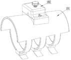
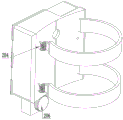
Further, the infusion part comprises: the solar energy collecting device comprises a shell a, a buckle cover b, a controller, a buckle, a pipe winding wheel, a knob c, a limiting plate c, a solar panel, a knob d, a shell b, a binding band b, an air bag a, an air bag b, an air valve, a limiting plate d, a connecting rod, an eccentric wheel, a battery, a conducting rod, a spring b, a conducting copper sheet, a coil spring, a belt winding wheel and a motor; the shell a is a hollow structure; a cylinder at one side of the buckle cover b is rotatably arranged on a round hole at one side of the shell a; the controller is fixedly arranged at the outer end of the buckle cover b; the number of the buckles is four, one ends of two buckles are fixedly arranged on one side of the lower end of the shell a, and one ends of the other two buckles are fixedly arranged on one ends of the two binding bands b; the cylinder of the pipe winding wheel is rotatably arranged in a round hole in the groove at the lower end of the shell a; the knob c is fixedly arranged at one end of the pipe winding wheel and is rotationally connected with the shell a; the limiting plate c is slidably arranged in the groove on one side of the shell a; the solar panel is fixedly arranged above the shell b; the knob d is rotatably arranged in a round hole on the shell b and is matched with a notch on the buckle cover b; the shell b is a hollow structure and is fixedly arranged at one end of the shell a; the number of the binding bands b is two, and one end of each binding band b is fixedly connected with the belt winding wheel; the air bag a is fixedly arranged in the shell a, and is positioned at the lower end of the limiting plate c; the number of the air bags b is two, the air bags b are fixedly arranged in the shell b, the air bags b are communicated with the air bags a through hoses, and one air bag b is provided with an opening and is matched with a piston arranged at the lower end of the buckle cover b; the air valve is fixedly arranged on an air inlet of the air bag b; the number of the limiting plates d is two, the limiting plates d are slidably mounted in the grooves in the shell a, and one end of each limiting plate d is fixedly connected with one end of the air bag b; the eccentric wheel is fixedly arranged on a motor shaft of the motor, two connecting rods are arranged, a round hole at one end of each connecting rod is rotatably arranged on a cylinder on the eccentric wheel, and a round hole at the other end of each connecting rod is rotatably arranged on a round hole at one side of the limiting plate d; the battery is fixedly arranged on one side of the shell a, the battery is communicated with the solar panel, the battery is communicated with the motor, and a conductive wire on one side of the battery communicated with the motor is a conductive copper sheet; the conducting rod is slidably arranged in a round hole on the shell a; one end of the spring b is fixedly connected with the shell a, and the other end of the spring b is fixedly connected with the conducting rod; a breakpoint is arranged in the middle of the conductive copper sheet and is matched with a conductive material arranged in the middle of the conductive rod; and four coil springs are arranged, one end of each coil spring is fixedly connected with the shell a, the other end of each coil spring is fixedly connected with the winding pulleys, the number of the winding pulleys is two, and the winding pulleys are rotatably arranged in the round holes in the shell a.
Due to the adoption of the technical scheme, the invention has the following advantages:
(1) the arm protecting part: sleeving the semicircular plate on the forearm of the patient, and fixing the semicircular plate on the forearm of the patient; then turning the knob b to open the buckle cover a; the limiting plate b can not generate oppression to the human body; realized the fixed action to the syringe needle, reduced the risk of running the needle, made when the human body is moving because of spring a, armguard part can make the syringe needle fix on the arm all the time, and the further syringe needle risk of running of reduction syringe needle has increased the security, easy operation.
(2) The transfusion part: when a patient needs to go to a toilet or the like and needs to move, the spring b generates elasticity, so that the liquid medicine can still enter a human body at a constant speed when the infusion part is fixed on the arm, the problem of liquid medicine backflow caused by the height difference between the arm protecting part and the infusion part when the human body moves is solved, the safety is improved, the operation is simple, and the patient can be moved conveniently.
(3) When the transfusion part is taken down, the bandage b is pulled out manually, so that the transfusion part is fixed on the arm of the patient; the function that the transfusion part can be fixed on the arm of the patient is realized, the operation is simple, and the convenience is improved; the patient can walk and move conveniently;
(4) the knob c is rotated, so that when the infusion part is placed on the arm, inconvenience caused by overlong infusion tube is avoided; the practicability is further improved, the operation is convenient, the convenience is further improved, and the patient can move conveniently.
Drawings
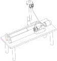
Fig. 1 is a schematic view of the present invention in a state of human body movement.
FIG. 2 is a schematic view of the present invention in a state of being on a patient's bed.
FIG. 3 is an overall schematic of the present invention.
Fig. 4 is an overall view of the armguard portion of the present invention.
Fig. 5 and 6 are schematic views of the internal structure of the arm guard part of the present invention.
Fig. 7 and 8 are overall schematic views of the infusion part of the invention.
Fig. 9, 10, 11 and 12 are schematic views of the internal structure of the infusion part of the invention.
Reference numerals: 1-a guard arm portion; 2-an infusion part; 101-a semicircular plate; 102-clasp cover a; 103-knob a; 104-limiting plate a; 105-spring a; 106-limiting plate b; 107-knob b; 108-band a; 109-elastic buckle; 201-housing a; 202-buckle cover b; 203-a controller; 204-buckling; 205-winding wheel; 206-knob c; 207-limiting plate c; 208-a solar panel; 209-knob d; 210-housing b; 211-band b; 212-balloon a; 213-airbag b; 214-a gas valve; 215-limiting plate d; 216-connecting rod; 217-eccentric wheel; 218-a battery; 219-a conductive rod; 220-spring b; 221-a conductive copper sheet; 222-a coil spring; 223-a belt winding wheel; 224-motor.
DETAILED DESCRIPTION OF EMBODIMENT (S) OF INVENTION
The technical scheme of the invention is further specifically described by the following embodiments and the accompanying drawings.
In the following description, numerous specific details are set forth in order to provide a thorough understanding of the present invention, but the present invention may be practiced in many ways other than those described herein, and it will be apparent to those skilled in the art that similar modifications can be made without departing from the spirit of the invention, and therefore the invention is not limited to the specific embodiments disclosed below.
In the description of the present invention, it should be noted that the terms "upper", "lower", "front", "back", "left", "right", and the like indicate orientations or positional relationships based on orientations or positional relationships shown in the drawings or orientations or positional relationships that the products of the present invention are conventionally placed in use, and are only used for convenience in describing the present invention and simplifying the description, but do not indicate or imply that the devices or elements referred to must have a specific orientation, be constructed in a specific orientation, and be operated, and thus, should not be construed as limiting the present invention.
1-12, an easy to move infusion device, comprising: a protective arm part 1 and a transfusion part 2; the arm protecting part 1 can be directly fixed with the forearm of a patient, and has the function of fixing the transfusion needle head, so that the needle head is not easy to run; the infusion part 2 place on the infusion support under normal conditions, the liquid medicine flows into patient internal according to normal gravity, when patient need move the messenger, can take off infusion part 2, fixes infusion part 2 on oneself's big arm, the liquid medicine is impressed the liquid medicine at the uniform velocity patient internal according to the inside atmospheric pressure structure that sets up, during this period, patient can remove at will for this infusion set has very big convenience.
In an alternative embodiment of the present invention, the arm protecting portion 1 includes, in addition to the same components as those of the previous embodiment: the semi-circular plate 101, a buckle cover a102, a knob a103, a limit plate a104, a spring a105, a limit plate b106, a knob b107, a binding band a108 and a tension buckle 109; the semicircular plate 101 is a plate approximately fitting the radian of the forearm of a human body; a cylinder at one side of the buckle cover a102 is rotatably arranged in a round hole at one side of the notch at the upper side of the semicircular plate 101; a cylinder at the lower end of the knob a103 is rotatably arranged in a round hole at the upper side of the buckle cover a102, and the cylinder of the knob a103 is in threaded engagement with the round hole on the buckle cover a 102; the limiting plate a104 is slidably arranged inside the buckle cover a102, and a round hole at the upper end of the limiting plate a104 is rotatably connected with a cylinder of the knob a 103; the number of the springs a105 is four, the upper ends of the springs a105 are fixedly connected with the lower end of the limiting plate a104, and the lower ends of the springs a105 are fixedly connected with the upper end of the limiting plate b 106; the limiting plate b106 is slidably arranged inside the buckle cover a 102; the knob b107 is rotatably arranged at the upper end of the notch of the semicircular plate 101, and the knob b107 is matched with the notch on the buckle cover a 102; six binding bands a108 are provided, every two binding bands a108 are divided into a group, and one end of each binding band a108 is fixedly arranged on two sides of the lower end of the semicircular plate 101; the number of the elastic buckles 109 is three, the elastic buckle 109 is fixedly arranged at one end of the binding band a108, and the groove of the elastic buckle 109 is in movable connection with the opposite binding band a 108.
In an alternative embodiment of the present invention, the infusion part 2 comprises, in addition to the same components as in the previous embodiment: the device comprises a shell a201, a buckle cover b202, a controller 203, a buckle 204, a pipe winding wheel 205, a knob c206, a limit plate c207, a solar panel 208, a knob d209, a shell b210, a strap b211, an air bag a212, an air bag b213, an air valve 214, a limit plate d215, a connecting rod 216, an eccentric wheel 217, a battery 218, a conductive rod 219, a spring b220, a conductive copper sheet 221, a coil spring 222, a belt winding wheel 223 and a motor 224; the shell a201 is a hollow structure; a cylinder at one side of the buckle cover b202 is rotatably arranged on a round hole at one side of the shell a 201; the controller 203 is fixedly arranged at the outer end of the buckle cover b 202; four buckles 204 are provided, one ends of two buckles 204 are fixedly arranged at one side of the lower end of the shell a201, and one ends of the other two buckles 204 are fixedly arranged at one ends of two binding bands b 211; the pipe wheel 205 is rotatably arranged in a round hole in the groove at the lower end of the shell a201 around the cylinder; the knob c206 is fixedly arranged at one end of the pipe winding wheel 205, and the knob c206 is rotatably connected with the shell a 201; the limiting plate c207 is slidably arranged in a groove at one side of the shell a 201; the solar panel 208 is fixedly arranged above the shell b 210; the knob d209 is rotatably installed in a round hole on the shell b210, and the knob d209 is matched with a notch on the buckle cover b 202; the shell b210 is a hollow structure, and the shell b210 is fixedly arranged at one end of the shell a 201; two binding bands b211 are provided, and one end of the binding band b211 is fixedly connected with the belt winding wheel 223; the air bag a212 is fixedly arranged inside the shell a201, and the air bag a212 is arranged at the lower end of the limiting plate c 207; the number of the air bags b213 is two, the air bags b213 are fixedly arranged in the shell b210, the air bags b213 and the air bags a212 are communicated through hoses, one air bag b213 is provided with an opening and is matched with a piston arranged at the lower end of the buckle cover b 202; the air valve 214 is fixedly arranged on the air inlet of the air bag b 213; two limiting plates d215 are arranged, the limiting plates d215 are slidably arranged in the grooves in the shell a201, and one end of each limiting plate d215 is fixedly connected with one end of the air bag b 213; the eccentric wheel 217 is fixedly arranged on a motor 224 shaft of a motor 224, two connecting rods 216 are arranged, a round hole at one end of each connecting rod 216 is rotatably arranged on a cylinder on the eccentric wheel 217, and a round hole at the other end of each connecting rod 216 is rotatably arranged on a round hole at one side of the limit plate d 215; the battery 218 is fixedly arranged at one side of the shell a201, the battery 218 is communicated with the solar panel 208, the battery 218 is communicated with the motor 224, and a conducting wire at one side of the battery 218 communicated with the motor 224 is a conducting copper sheet 221; the conducting rod 219 is slidably arranged in a round hole on the shell a 201; one end of the spring b220 is fixedly connected with the shell a201, and the other end of the spring b220 is fixedly connected with the conducting rod 219; a break point is arranged in the middle of the conductive copper sheet 221 and is matched with the conductive material arranged in the middle of the conductive rod 219; the number of the coil springs 222 is four, one end of each coil spring 222 is fixedly connected with the shell a201, the other end of each coil spring 222 is fixedly connected with the winding pulleys 223, the number of the winding pulleys 223 is two, and the winding pulleys 223 are rotatably arranged in circular holes in the shell a 201.
The working principle is as follows:
the principle of the arm guard part 1 is: firstly loosening the binding belt a108, sleeving the semicircular plate 101 on the forearm of the patient, and then tightening the binding belt a108 by means of the elastic buckle 109 to fix the semicircular plate 101 on the forearm of the patient; turning the knob b107 to open the buckle cover a 102; then, the professional inserts the needle into the human body to carry out simple fixation; closing the buckle cover a102, and rotating the knob b107 to clamp the buckle cover a 102; rotating the knob a103, and enabling the knob a103 to prop against the limit plate a104 to move downwards; the limiting plate a104 drives the limiting plate b106 to move downwards through the spring a105, the limiting plate b106 further fixes the needle, and when the human body slightly moves, the limiting plate b106 does not generate oppression to the human body due to the existence of the spring a 105; realized the fixed action to the syringe needle, reduced the risk of running the needle, because of spring a105 makes when the human body is in the motion, armguard part 1 can make the syringe needle fix on the arm all the time, and the further needle risk of running that reduces the syringe needle has increased the security, easy operation.
The working principle of the transfusion part 2 is as follows: rotating the knob d209, opening the buckle cover b202, putting the liquid medicine bag into the shell a201, closing the buckle cover b202, and rotating the knob d209 to lock the buckle cover b 202; the infusion tube is wound on the tube winding wheel 205; the transfusion part 2 is hung on a transfusion stand and is used normally; when a patient needs to go to a toilet or the like to move, the infusion part 2 can be removed, when the infusion part 2 is removed, the spring b220 generates elastic force to prop against the conductive rod 219 to move downwards, the conductive material of the conductive rod 219 is communicated with the conductive copper sheet 221, the motor 224 is communicated with the battery 218, then the motor 224 works, the motor 224 drives the eccentric wheel 217 to work, the eccentric wheel 217 drives the connecting rod 216 to move, the connecting rod 216 drives the two limit plates d215 to move back and forth, and the limit plates d215 drive the air bag b213 to exhaust air; because the connecting rod 216 is coaxial on the eccentric wheel 217, the limiting plate d215 alternately performs air suction and air discharge movement on the air bag b213, and because the air valve 214 is arranged, the air bag b213 inflates the air bag a212, and the volume of the air bag a212 is increased; the air bag a212 jacks up the limiting plate c207 to move upwards, and the limiting plate c207 extrudes the liquid medicine bag to enable the liquid medicine to enter a human body at a constant speed; the problem that liquid medicine flows back due to the height difference between the arm protection part 1 and the infusion part 2 when the infusion part 2 is fixed on the arm is solved, safety is improved, operation is simple, and the patient can move conveniently.
When the transfusion part 2 is taken down, the binding band b211 is manually pulled out, the binding band b211 surrounds the arm for a circle, the buckle 204 on the binding band b211 hooks the buckle 204 at the lower end of the shell a201, the two are clamped, and then the coil spring 222 rebounds to tighten the binding band b 211; the transfusion part 2 is fixed on the arm of the patient; the function that the transfusion part 2 can be fixed on the arm of the patient is realized, the operation is simple, and the convenience is improved; the patient can walk and move conveniently;
the knob c206 is rotated, the knob c206 drives the tube winding wheel 205 to rotate, and the tube winding wheel 205 rotates, so that the grown infusion tube is wound on the tube winding wheel 205; when the transfusion part 2 is put on the arm, the inconvenience caused by overlong transfusion tube can be avoided; the practicability is further improved, the operation is convenient, the convenience is further improved, and the patient can move conveniently.
Claims (2)
1. A portable infusion device, comprising: a protective arm part (1) and a transfusion part (2); the arm protecting part (1) can be directly fixed with the forearm of a patient, and has the function of fixing the transfusion needle head, so that the needle head is not easy to run; the infusion part (2) is normally placed on an infusion support, liquid medicine flows into a patient body according to normal gravity, when the patient needs to move, the infusion part (2) can be taken off, the infusion part (2) is fixed on the big arm of the patient, the liquid medicine is uniformly pressed into the patient body according to an air pressure structure arranged inside, and the patient can move freely during the period, so that the infusion device has great convenience; the arm-protecting part (1) comprises: the device comprises a semicircular plate (101), a buckle cover a (102), a knob a (103), a limit plate a (104), a spring a (105), a limit plate b (106), a knob b (107), a binding band a (108) and a buckle (109); the semicircular plate (101) is a plate approximately fitting the radian of the forearm of a human body; a cylinder at one side of the buckle cover a (102) is rotatably arranged in a round hole at one side of the notch at the upper side of the semicircular plate (101); a cylinder at the lower end of the knob a (103) is rotatably arranged in a round hole at the upper side of the buckle cover a (102), and the cylinder of the knob a (103) is in threaded engagement with the round hole on the buckle cover a (102); the limiting plate a (104) is slidably arranged inside the buckle cover a (102), and a round hole in the upper end of the limiting plate a (104) is rotatably connected with a cylinder of the knob a (103); the number of the springs a (105) is four, the upper ends of the springs a (105) are fixedly connected with the lower end of the limiting plate a (104), and the lower ends of the springs a (105) are fixedly connected with the upper end of the limiting plate b (106); the limiting plate b (106) is slidably arranged inside the buckle cover a (102); the knob b (107) is rotatably arranged at the upper end of the notch of the semicircular plate (101), and the knob b (107) is matched with the notch on the buckle cover a (102); six binding bands a (108) are provided, every two binding bands a (108) are divided into a group, and one end of each binding band a (108) is fixedly arranged on two sides of the lower end of the semicircular plate (101); the number of the elastic buckles (109) is three, the elastic buckles (109) are fixedly arranged at one end of the binding band a (108), and the grooves of the elastic buckles (109) are matched and movably connected with the opposite binding band a (108).
2. A portable infusion device according to claim 1, wherein said infusion part (2) comprises: the solar energy water heater comprises a shell a (201), a buckle cover b (202), a controller (203), a buckle (204), a pipe winding wheel (205), a knob c (206), a limit plate c (207), a solar panel (208), a knob d (209), a shell b (210), a bandage b (211), an air bag a (212), an air bag b (213), an air valve (214), a limit plate d (215), a connecting rod (216), an eccentric wheel (217), a battery (218), a conductive rod (219), a spring b (220), a conductive copper sheet (221), a coil spring (222), a belt winding wheel (223) and a motor (224); the shell a (201) is a hollow structure; a cylinder at one side of the buckle cover b (202) is rotatably arranged on a round hole at one side of the shell a (201); the controller (203) is fixedly arranged at the outer end of the buckle cover b (202); the number of the buckles (204) is four, one ends of two buckles (204) are fixedly arranged on one side of the lower end of the shell a (201), and one ends of the other two buckles (204) are fixedly arranged on one ends of two binding bands b (211); the cylindrical winding wheel (205) is rotatably arranged in a round hole in the groove at the lower end of the shell a (201); the knob c (206) is fixedly arranged at one end of the pipe winding wheel (205), and the knob c (206) is rotatably connected with the shell a (201); the limiting plate c (207) is slidably arranged in a groove on one side of the shell a (201); the solar panel (208) is fixedly arranged above the shell b (210); the knob d (209) is rotatably arranged in a round hole on the shell b (210), and the knob d (209) is matched with a notch on the buckle cover b (202); the shell b (210) is a hollow structure, and the shell b (210) is fixedly arranged at one end of the shell a (201); two binding bands b (211) are provided, and one end of each binding band b (211) is fixedly connected with the winding wheel (223); the air bag a (212) is fixedly arranged inside the shell a (201), and the air bag a (212) is positioned at the lower end of the limiting plate c (207); the number of the air bags b (213) is two, the air bags b (213) are fixedly arranged in the shell b (210), the air bags b (213) are communicated with the air bags a (212) through hoses, one air bag b (213) is provided with an opening and is matched with a piston arranged at the lower end of the buckle cover b (202); the air valve (214) is fixedly arranged on an air inlet of the air bag b (213); two limiting plates d (215) are arranged, the limiting plates d (215) are slidably mounted in the grooves in the shell a (201), and one end of each limiting plate d (215) is fixedly connected with one end of the air bag b (213); the eccentric wheel (217) is fixedly arranged on a motor (224) shaft of the motor (224), two connecting rods (216) are arranged, a round hole at one end of each connecting rod (216) is rotatably arranged on a cylinder on the eccentric wheel (217), and a round hole at the other end of each connecting rod (216) is rotatably arranged on a round hole at one side of the limiting plate d (215); the battery (218) is fixedly arranged on one side of the shell a (201), the battery (218) is communicated with the solar panel (208), the battery (218) is communicated with the motor (224), and a conductive wire on one side, communicated with the motor (224), of the battery (218) is a conductive copper sheet (221); the conducting rod (219) is slidably arranged in a round hole on the shell a (201); one end of a spring b (220) is fixedly connected with the shell a (201), and the other end of the spring b (220) is fixedly connected with a conductive rod (219); a break point is arranged in the middle of the conductive copper sheet (221) and is matched with a conductive material arranged in the middle of the conductive rod (219); four coil springs (222) are provided, one end of each coil spring (222) is fixedly connected with the shell a (201), the other end of each coil spring (222) is fixedly connected with the two winding wheels (223), and the two winding wheels (223) are rotatably arranged in circular holes in the shell a (201).
Priority Applications (1)
| Application Number | Priority Date | Filing Date | Title |
|---|---|---|---|
| CN202011427419.7A CN112546330A (en) | 2020-12-09 | 2020-12-09 | Infusion device convenient to move |
Applications Claiming Priority (1)
| Application Number | Priority Date | Filing Date | Title |
|---|---|---|---|
| CN202011427419.7A CN112546330A (en) | 2020-12-09 | 2020-12-09 | Infusion device convenient to move |
Publications (1)
| Publication Number | Publication Date |
|---|---|
| CN112546330A true CN112546330A (en) | 2021-03-26 |
Family
ID=75060664
Family Applications (1)
| Application Number | Title | Priority Date | Filing Date |
|---|---|---|---|
| CN202011427419.7A Pending CN112546330A (en) | 2020-12-09 | 2020-12-09 | Infusion device convenient to move |
Country Status (1)
| Country | Link |
|---|---|
| CN (1) | CN112546330A (en) |
Citations (14)
| Publication number | Priority date | Publication date | Assignee | Title |
|---|---|---|---|---|
| CN201643175U (en) * | 2010-05-10 | 2010-11-24 | 万晨阳 | Portable infusion device |
| JP2010264117A (en) * | 2009-05-15 | 2010-11-25 | Medical R&D Co Ltd | Infusion pack suspending assembly |
| CN203954333U (en) * | 2014-01-17 | 2014-11-26 | 林刚 | Transfusion needle fixture |
| CN204379898U (en) * | 2014-12-31 | 2015-06-10 | 江西科技学院 | A kind of Portable Automatic extruding transfusion device |
| CN204798486U (en) * | 2015-05-22 | 2015-11-25 | 陆国忠 | Can be along with human infusion set who removes |
| CN107802910A (en) * | 2017-11-17 | 2018-03-16 | 孙美岩 | A kind of big internal medicine transfusion nursing device |
| CN108261578A (en) * | 2018-03-16 | 2018-07-10 | 湖州健凯康复产品有限公司 | A kind of traction adding pressure type arm assisted transfusion device |
| CN108261579A (en) * | 2018-03-16 | 2018-07-10 | 湖州健凯康复产品有限公司 | A kind of electromagnet type transfusion auxiliary device |
| CN108310534A (en) * | 2018-01-26 | 2018-07-24 | 苏州百源基因技术有限公司 | A kind of Portable transfusion apparatus |
| CN209596312U (en) * | 2019-01-28 | 2019-11-08 | 中南大学湘雅三医院 | A kind of nurse's anti-dropout infusion device |
| WO2020094439A1 (en) * | 2018-11-09 | 2020-05-14 | Pfm Medical Ag | Mobile hydration system for infusing an infusion liquid, in particular a saline solution or ringer's solution, into the human or animal body |
| CN210904412U (en) * | 2019-05-14 | 2020-07-03 | 上海长海医院 | Liquid fixing device of infusion apparatus |
| CN211024509U (en) * | 2019-07-26 | 2020-07-17 | 东海县人民医院 | Portable shoulder-carrying infusion device |
| CN211214731U (en) * | 2019-07-11 | 2020-08-11 | 宋炳全 | Portable infusion device |
-
2020
- 2020-12-09 CN CN202011427419.7A patent/CN112546330A/en active Pending
Patent Citations (14)
| Publication number | Priority date | Publication date | Assignee | Title |
|---|---|---|---|---|
| JP2010264117A (en) * | 2009-05-15 | 2010-11-25 | Medical R&D Co Ltd | Infusion pack suspending assembly |
| CN201643175U (en) * | 2010-05-10 | 2010-11-24 | 万晨阳 | Portable infusion device |
| CN203954333U (en) * | 2014-01-17 | 2014-11-26 | 林刚 | Transfusion needle fixture |
| CN204379898U (en) * | 2014-12-31 | 2015-06-10 | 江西科技学院 | A kind of Portable Automatic extruding transfusion device |
| CN204798486U (en) * | 2015-05-22 | 2015-11-25 | 陆国忠 | Can be along with human infusion set who removes |
| CN107802910A (en) * | 2017-11-17 | 2018-03-16 | 孙美岩 | A kind of big internal medicine transfusion nursing device |
| CN108310534A (en) * | 2018-01-26 | 2018-07-24 | 苏州百源基因技术有限公司 | A kind of Portable transfusion apparatus |
| CN108261578A (en) * | 2018-03-16 | 2018-07-10 | 湖州健凯康复产品有限公司 | A kind of traction adding pressure type arm assisted transfusion device |
| CN108261579A (en) * | 2018-03-16 | 2018-07-10 | 湖州健凯康复产品有限公司 | A kind of electromagnet type transfusion auxiliary device |
| WO2020094439A1 (en) * | 2018-11-09 | 2020-05-14 | Pfm Medical Ag | Mobile hydration system for infusing an infusion liquid, in particular a saline solution or ringer's solution, into the human or animal body |
| CN209596312U (en) * | 2019-01-28 | 2019-11-08 | 中南大学湘雅三医院 | A kind of nurse's anti-dropout infusion device |
| CN210904412U (en) * | 2019-05-14 | 2020-07-03 | 上海长海医院 | Liquid fixing device of infusion apparatus |
| CN211214731U (en) * | 2019-07-11 | 2020-08-11 | 宋炳全 | Portable infusion device |
| CN211024509U (en) * | 2019-07-26 | 2020-07-17 | 东海县人民医院 | Portable shoulder-carrying infusion device |
Similar Documents
| Publication | Publication Date | Title |
|---|---|---|
| CN210785030U (en) | Emergency nursing is with wrapping device | |
| CN112546330A (en) | Infusion device convenient to move | |
| CN112933314A (en) | Dialysis infusion support | |
| CN217472505U (en) | Child arm fixer for preventing needle from being pulled out | |
| CN209490351U (en) | Novel foundation nursing oxygen therapy tube fixing device | |
| CN213100149U (en) | Intensive care unit breathing machine pipeline fixer | |
| CN213667293U (en) | Portable transfusion needle recoverer | |
| RU94846U1 (en) | DEVICE FOR EXTENSION AND FIXING OF THE PENIS | |
| CN213588356U (en) | Hump nose auxiliary instrument that plastic surgery used | |
| CN218792947U (en) | Clinical limb fixing frame | |
| CN214485179U (en) | Drainage bag with adjustable length | |
| CN211534894U (en) | Tooth separation strutting arrangement | |
| CN215023430U (en) | Portable blood purifies nursing device | |
| CN115092774A (en) | Surgical intensive care unit pipeline carding unit | |
| CN212141061U (en) | Pediatric clinical infusion protector | |
| CN201139818Y (en) | Medical vein pricking device for transfusion | |
| CN219558290U (en) | Medical infusion leather hose anti-drop device | |
| CN216455539U (en) | Radius distal end fracture fixation brace | |
| CN218186883U (en) | Gallbladder calculus removing device for general surgery department | |
| CN215013907U (en) | Protective gloves for preparing liquid medicine | |
| CN215135577U (en) | Hemodialysis pipeline fixer | |
| CN209449624U (en) | A kind of Chinese chestnut sheller safety guard net using expansion principle | |
| CN219557304U (en) | Puncture-preventing blood taking needle device | |
| CN218572591U (en) | Portable multifunctional venipuncture body position support | |
| CN213963749U (en) | Guinea pig injection device with capture function |
Legal Events
| Date | Code | Title | Description |
|---|---|---|---|
| PB01 | Publication | ||
| PB01 | Publication | ||
| SE01 | Entry into force of request for substantive examination | ||
| SE01 | Entry into force of request for substantive examination | ||
| WD01 | Invention patent application deemed withdrawn after publication | ||
| WD01 | Invention patent application deemed withdrawn after publication |
Application publication date: 20210326 |