CN112534475B - Self-supervised training of depth estimation systems - Google Patents
Self-supervised training of depth estimation systems Download PDFInfo
- Publication number
- CN112534475B CN112534475B CN201980047649.XA CN201980047649A CN112534475B CN 112534475 B CN112534475 B CN 112534475B CN 201980047649 A CN201980047649 A CN 201980047649A CN 112534475 B CN112534475 B CN 112534475B
- Authority
- CN
- China
- Prior art keywords
- image
- depth
- difference
- composite frame
- timestamp
- Prior art date
- Legal status (The legal status is an assumption and is not a legal conclusion. Google has not performed a legal analysis and makes no representation as to the accuracy of the status listed.)
- Active
Links
Images


Classifications
-
- G—PHYSICS
- G06—COMPUTING; CALCULATING OR COUNTING
- G06T—IMAGE DATA PROCESSING OR GENERATION, IN GENERAL
- G06T7/00—Image analysis
- G06T7/50—Depth or shape recovery
- G06T7/55—Depth or shape recovery from multiple images
- G06T7/593—Depth or shape recovery from multiple images from stereo images
-
- H—ELECTRICITY
- H04—ELECTRIC COMMUNICATION TECHNIQUE
- H04N—PICTORIAL COMMUNICATION, e.g. TELEVISION
- H04N13/00—Stereoscopic video systems; Multi-view video systems; Details thereof
- H04N13/20—Image signal generators
- H04N13/271—Image signal generators wherein the generated image signals comprise depth maps or disparity maps
-
- G—PHYSICS
- G06—COMPUTING; CALCULATING OR COUNTING
- G06T—IMAGE DATA PROCESSING OR GENERATION, IN GENERAL
- G06T7/00—Image analysis
- G06T7/30—Determination of transform parameters for the alignment of images, i.e. image registration
-
- G—PHYSICS
- G06—COMPUTING; CALCULATING OR COUNTING
- G06T—IMAGE DATA PROCESSING OR GENERATION, IN GENERAL
- G06T7/00—Image analysis
- G06T7/50—Depth or shape recovery
- G06T7/55—Depth or shape recovery from multiple images
- G06T7/579—Depth or shape recovery from multiple images from motion
-
- G—PHYSICS
- G06—COMPUTING; CALCULATING OR COUNTING
- G06T—IMAGE DATA PROCESSING OR GENERATION, IN GENERAL
- G06T7/00—Image analysis
- G06T7/70—Determining position or orientation of objects or cameras
- G06T7/73—Determining position or orientation of objects or cameras using feature-based methods
-
- G—PHYSICS
- G06—COMPUTING; CALCULATING OR COUNTING
- G06T—IMAGE DATA PROCESSING OR GENERATION, IN GENERAL
- G06T7/00—Image analysis
- G06T7/97—Determining parameters from multiple pictures
-
- G—PHYSICS
- G06—COMPUTING; CALCULATING OR COUNTING
- G06T—IMAGE DATA PROCESSING OR GENERATION, IN GENERAL
- G06T2207/00—Indexing scheme for image analysis or image enhancement
- G06T2207/10—Image acquisition modality
- G06T2207/10016—Video; Image sequence
-
- G—PHYSICS
- G06—COMPUTING; CALCULATING OR COUNTING
- G06T—IMAGE DATA PROCESSING OR GENERATION, IN GENERAL
- G06T2207/00—Indexing scheme for image analysis or image enhancement
- G06T2207/10—Image acquisition modality
- G06T2207/10028—Range image; Depth image; 3D point clouds
-
- G—PHYSICS
- G06—COMPUTING; CALCULATING OR COUNTING
- G06T—IMAGE DATA PROCESSING OR GENERATION, IN GENERAL
- G06T2207/00—Indexing scheme for image analysis or image enhancement
- G06T2207/20—Special algorithmic details
- G06T2207/20081—Training; Learning
-
- G—PHYSICS
- G06—COMPUTING; CALCULATING OR COUNTING
- G06T—IMAGE DATA PROCESSING OR GENERATION, IN GENERAL
- G06T2207/00—Indexing scheme for image analysis or image enhancement
- G06T2207/20—Special algorithmic details
- G06T2207/20084—Artificial neural networks [ANN]
-
- G—PHYSICS
- G06—COMPUTING; CALCULATING OR COUNTING
- G06T—IMAGE DATA PROCESSING OR GENERATION, IN GENERAL
- G06T2207/00—Indexing scheme for image analysis or image enhancement
- G06T2207/30—Subject of image; Context of image processing
- G06T2207/30244—Camera pose
-
- H—ELECTRICITY
- H04—ELECTRIC COMMUNICATION TECHNIQUE
- H04N—PICTORIAL COMMUNICATION, e.g. TELEVISION
- H04N13/00—Stereoscopic video systems; Multi-view video systems; Details thereof
- H04N13/20—Image signal generators
- H04N13/204—Image signal generators using stereoscopic image cameras
- H04N13/239—Image signal generators using stereoscopic image cameras using two 2D image sensors having a relative position equal to or related to the interocular distance
-
- H—ELECTRICITY
- H04—ELECTRIC COMMUNICATION TECHNIQUE
- H04N—PICTORIAL COMMUNICATION, e.g. TELEVISION
- H04N13/00—Stereoscopic video systems; Multi-view video systems; Details thereof
- H04N2013/0074—Stereoscopic image analysis
- H04N2013/0081—Depth or disparity estimation from stereoscopic image signals
-
- H—ELECTRICITY
- H04—ELECTRIC COMMUNICATION TECHNIQUE
- H04N—PICTORIAL COMMUNICATION, e.g. TELEVISION
- H04N13/00—Stereoscopic video systems; Multi-view video systems; Details thereof
- H04N2013/0074—Stereoscopic image analysis
- H04N2013/0088—Synthesising a monoscopic image signal from stereoscopic images, e.g. synthesising a panoramic or high resolution monoscopic image
Abstract
A method for training a depth estimation model and a method of using the same are described. The images are acquired and input into a depth model to extract a depth map for each of the plurality of images based on parameters of the depth model. The method includes inputting images into a pose decoder to extract a pose for each image. The method includes generating a plurality of composite frames based on the depth map and pose for each image. The method includes calculating a loss value using an input proportional occlusion and motion perception loss function based on a comparison of the composite frame and the image. The method includes adjusting a plurality of parameters of the depth model based on the loss values. The trained model may receive an image of a scene and generate a depth map of the scene from the image.
Description
Technical Field
The described subject matter relates generally to estimating depth maps from monochromatic input images, and in particular to machine learning models for estimating depth maps trained using video data and/or stereo image data.
Background
Depth sensing has applications in both navigation and scene understanding. Many methods use a trained model or network to determine a depth map from a monochromatic input image. There are several methods to train the depth estimation system using different kinds of training data. The depth estimation system may be trained using a detection and ranging system to establish ground true depth (i.e., radio detection and ranging (RADAR), light detection and ranging (LIDAR), etc.) for objects in an environment paired with images of the same scene acquired by a camera. While detection and ranging systems may provide ground truth in object depth, continually utilizing detection and ranging systems to sense the depth of many different environments may be a costly endeavor in terms of time and resources. Furthermore, the detection and ranging system is unable to determine the depth of some objects (e.g., reflective objects) whose material properties may make them undetectable by the detection and ranging system.
Another method of training a depth estimation system is to utilize stereo image pairs of the same scene. Capturing a stereoscopic image pair at a single instant of time depends on using two cameras that are focused on the same scene but at a distance. The depth estimation system operates by projecting from one stereo image of a stereo image pair to the other stereo image. In order to project each other, the depth estimation system considers the current stereo image in addition to the disparity (scaled inverse of depth) and relative transformation between the physical positions of the two cameras used to acquire the stereo image pair. The depth estimation system may determine the depth of the scene while minimizing a photometric reconstruction error (photometric reconstruction error) of the projection compared to the captured stereo image.
Some of the more novel approaches train a depth estimation system with monocular video data of a changing scene. The depth estimation system is trained by: a temporal image (temporal image) in monocular video data is projected to a subsequent temporal image while minimizing photometric reconstruction errors. However, from one time image to another, such systems may misinterpret objects entering or leaving the field of view, which may result in artifacts near the depth map and the depth map boundaries. Furthermore, prior to upsampling the depth map, conventional systems currently input a low resolution image that is used to determine the depth map, which is prone to depth upsampling artifacts.
Disclosure of Invention
The present disclosure describes a method for training and using a depth estimation model. To train the model, the system acquires images. The system inputs the images into a depth model to extract a depth map for each image based on the parameters of the depth model. The system inputs the images into a pose decoder to extract a pose for each image. The system generates a composite frame based on the depth map and pose for each image. The system calculates a loss value based on a comparison of the synthesized frame and the image using the input scale occlusion and motion perception loss functions. The input proportional occlusion and motion perception loss functions calculate loss values for optimizing parameters of the depth model. The loss function includes calculating a photometric reconstruction error for each pixel between the synthesized frame and the input image. The loss function may also take into account a minimum photometric reconstruction error between two synthesized frames projected from multiple temporal images from the monocular video, which are temporally adjacent. Upsampled depth features may also be used during the generation of composite frames, which will affect the computation of the appearance matching loss. The loss function may also implement a generated mask that reduces static features in the image when calculating the loss value. The system adjusts parameters of the depth model based on the loss values. With the trained model, the device may receive an image of the scene and generate a depth map of the scene from the image.
In some embodiments, the depth estimation model is trained using image data comprising monocular video. Each image of the monocular video is captured at a different time and associated with a corresponding timestamp. In an example discussion using a first image with a first timestamp and a second image with a second timestamp, the model uses the first image with the first timestamp from the monocular video to generate a composite frame at the second timestamp. The model calculates a photometric reconstruction error between the composite frame and a second image having a second time stamp. The model follows the above process, with other image pairs from the monocular video having neighboring timestamps. The model adjusts the parameters to minimize the error. In other embodiments, the model is trained using image data comprising stereo image pairs, wherein each stereo image pair is captured by a stereo camera pair. When generating a composite frame, the model acquires one of the images (e.g., the left image) from the stereoscopic image pair and generates a composite frame at the other image (e.g., the right image). The model calculates the photometric reconstruction error between the synthesized frame and the other images. The model adjusts the parameters to minimize the error. In other embodiments, the model is trained using image data comprising a monocular video and stereo image pair.
Drawings
FIG. 1 illustrates a networked computing environment in accordance with one or more embodiments.
FIG. 2 depicts a representation of a virtual world having a geographic environment parallel to the real world in accordance with one or more embodiments.
FIG. 3 depicts an exemplary game interface for a parallel reality game in accordance with one or more embodiments.
FIG. 4 illustrates a conceptual comparison of using a separate pose estimation model and a depth-pose hybrid model in accordance with one or more embodiments.
FIG. 5 is a flow diagram describing a general process for training a depth estimation model in accordance with one or more embodiments.
FIG. 6 is a flow diagram that describes a general process for using a depth estimation model in accordance with one or more embodiments.
FIG. 7 is an example architecture of a computing device in accordance with one or more embodiments.
The figures and the following description depict certain embodiments by way of illustration only. One skilled in the art will readily recognize from the following description that alternative embodiments of the structures and methods may be employed without departing from the principles described. Reference will now be made to several embodiments, examples of which are illustrated in the accompanying drawings.
Detailed Description
Exemplary location-based parallel reality gaming System (parallel gaming system)
A parallel reality game is a location-based game having a virtual world geographic environment that is parallel to at least a portion of the real world geographic environment such that movement and action of a player in the real world affects action in the virtual world, and vice versa. Those of ordinary skill in the art, using the disclosure provided herein, will understand that: the described subject matter is applicable to other situations in which it is desirable to determine depth information from image data. In addition, the inherent flexibility of computer-based systems allows for a variety of possible configurations, combinations, and divisions of tasks and functions among the components of the system. For example, systems and methods according to aspects of the present disclosure may be implemented using a single computing device or across multiple computing devices (e.g., connected in a computer network).
FIG. 1 illustrates a networked computing environment 100 in accordance with one or more embodiments. The networked computing environment 100 provides for player interaction in a virtual world having a geographic environment that is parallel to the real world. In particular, geographic regions in the real world may be directly linked or mapped to corresponding regions in the virtual world. By moving to various geographic locations in the real world, players can move in the virtual world. For example, the player's location in the real world may be tracked and used to update the player's location in the virtual world. Typically, the position of a player in the real world is determined by: the location of the client device 110 (through which the player is interacting with the virtual world) is found, and the player is assumed to be in the same (or approximately the same) location as the client device 110. For example, in various embodiments, a player may interact with a virtual element if the player's location in the real world is within a threshold distance (e.g., ten meters, twenty meters, etc.) of the real world location (which corresponds to the virtual location of the virtual element in the virtual world). For convenience, various embodiments are described with reference to a "location of a player," but those skilled in the art will appreciate that such reference may refer to a location of a player's client device 110.
Referring now to FIG. 2, FIG. 2 depicts a conceptual diagram of a virtual world 210 parallel to a real world 200 (the real world 200 may serve as a gameboard for a player of a parallel reality game), according to one embodiment. As shown, the virtual world 210 may include a geographic environment that is parallel to the geographic environment of the real world 200. Specifically, coordinate ranges defining a geographic region or space in the real world 200 are mapped to corresponding coordinate ranges defining a virtual space in the virtual world 210. The coordinate ranges in the real world 200 may be associated with towns, blocks, cities, campuses, places, countries, continents, the entire earth, or other geographic areas. Each geographic coordinate within the range of geographic coordinates is mapped to a corresponding coordinate in a virtual space in the virtual world.
The player's location in the virtual world 210 corresponds to the player's location in the real world 200. For example, player a, located at location 212 in the real world 200, has a corresponding location 222 in the virtual world 210. Similarly, player B, located at position 214 in the real world, has a corresponding position 224 in the virtual world. As the player moves within the geographic coordinate range in the real world, the player also moves within the coordinate range that defines the virtual space in the virtual world 210. In particular, a positioning system (e.g., a GPS system) associated with a mobile computing device carried by the player may be used to track the player's location as the player navigates within geographic coordinates in the real world. The data associated with the player's position in the real world 200 is used to update the player's position within the corresponding coordinate range that defines the virtual space in the virtual world 210. In this manner, by simply traveling within the corresponding geographic coordinate range in the real world 200, the player may navigate along a continuous trajectory within the coordinate range defining the virtual space in the virtual world 210 without having to report or periodically update location information at specific discrete locations in the real world 200.
A location-based game may include a plurality of game targets that require a player to travel to and/or interact with various virtual elements and/or virtual objects dispersed at various virtual locations in a virtual world. The player may travel to these virtual locations by traveling to the virtual elements or objects' corresponding locations in the real world. For example, the positioning system may continuously track the player's position so that as the player continuously navigates in the real world, the player also continuously navigates in the parallel virtual world. The player may then interact with various virtual elements and/or objects at specific locations to achieve or perform one or more game goals.
For example, the game objects have players that interact with virtual elements 230 located at various virtual positions in the virtual world 210. These virtual elements 230 may be linked to landmarks, geographic locations, or objects 240 in the real world 200. The real-world landmark or object 240 may be an artwork, monument, building, business, library, museum, or other suitable real-world landmark or object. Interactions include capturing, claiming ownership, using a certain virtual item, spending some virtual currency, etc. To capture these virtual elements 230, the player must travel to a landmark or geographic location 240 in the real world that is linked to the virtual element 230, and must perform any necessary interactions with the virtual element 230 in the virtual world 210. For example, player a in fig. 2 may have to travel to a landmark 240 in the real world 200 in order to interact with the virtual element 230 (which is linked to the particular landmark 240) or to capture the virtual element 230. Interaction with the virtual element 230 may require action in the real world, such as taking a photograph and/or verifying, obtaining, or capturing other information about a landmark or object 240 associated with the virtual element 230.
The game goal may require the player to use one or more virtual items collected by the player in the location-based game. For example, a player may travel through the virtual world 210 to find virtual items (e.g., weapons, creatures, props, or other items) that are useful for accomplishing game goals. These virtual items may be found or collected by traveling to different locations in the real world 200, or by performing various actions in the virtual world 210 or the real world 200. In the example shown in FIG. 2, the player uses a virtual item 232 to capture one or more virtual elements 230. In particular, the player may deploy the virtual item 232 at a location in the virtual world 210 that is near the virtual element 230, or at a location in the virtual element 230. Deploying one or more virtual items 232 in this manner may result in the capture of virtual elements 230 for a particular player or for a team/battle of a particular player.
In one particular implementation, a player may have to collect virtual energy as part of a parallel reality game. As shown in fig. 2, the virtual energy 250 may be spread at different locations in the virtual world 210. The player may collect virtual energy 250 by proceeding to the corresponding location of virtual energy 250 in real world 200. The virtual energy 250 may be used to power virtual items and/or to perform various game goals in the game. A player who loses all of the virtual energy 250 may disconnect from the game.
According to aspects of the present disclosure, the parallel reality game may be a massively multiplayer, location-based game, where each participant in the game shares the same virtual world. Players may be divided into different teams or teams and may work together to achieve one or more game goals, such as capturing or claiming ownership of a virtual element. In this manner, the parallel reality game may be, in essence, a social game that encourages cooperation among players within the game. During a parallel reality game, players from teams of opponents may play against each other (or sometimes collaborate to reach a common goal). Players may use virtual items to attack or impede progress of players of opposing teams. In some cases, players are encouraged to congregate at multiple locations in the real world to play collaborative or interactive events in a parallel reality game. In these cases, the game server attempts to ensure that the player is actually present and not cheated.
The parallel reality game may have various features to enhance and encourage game play in the parallel reality game. For example, a player may accumulate virtual currency or other virtual awards (e.g., virtual tokens, virtual points, virtual material resources, etc.) that may be used throughout the game (e.g., to purchase items in the game, exchange for other items, make items, etc.). As a player completes one or more game goals and gains experience in the game, the player may proceed to various levels. In some embodiments, players may communicate with each other through one or more communication interfaces provided in the game. The player may also acquire enhanced "powers" or virtual items that may be used to accomplish game goals in the game. One of ordinary skill in the art, using the disclosure provided herein, will appreciate that the parallel reality game may include various other game features without departing from the scope of the present disclosure.
Referring again to FIG. 1, the networked computing environment 100 uses a client-server architecture, where a game server 120 communicates with a client device 110 over a network 105 to provide a parallel reality game to players at the client device 110. The networked computing environment 100 may also include other external systems, such as sponsor/advertiser systems or business systems. Although only one client device 110 is shown in fig. 1, any number of clients 110 or other external systems may be connected to the game server 120 through the network 105. Moreover, the networked computing environment 100 may contain different or additional elements, and functionality may be distributed between the client device 110 and the server 120 in different manners than described below.
The client device 110 may be any portable computing device that a player may use to interface with the game server 120. For example, the client device 110 may be a wireless device, a Personal Digital Assistant (PDA), a portable device. A gaming device, a cellular phone, a smart phone, a tablet, a navigation system, a handheld GPS system, a wearable computing device, a display with one or more processors, or other such devices. In another example, client device 110 comprises a conventional computer system, such as a desktop computer or laptop computer. Still, the client device 110 may be a vehicle having a computing device. In short, the client device 110 may be any computer device or system that enables a player to interact with the game server 120. As a computing device, client device 110 may include one or more processors and one or more computer-readable storage media. The computer readable storage medium may store instructions that cause a processor to perform operations. Client device 110 is preferably a portable computing device that can be easily carried or otherwise transported with a player, such as a smartphone or tablet.
The client device 110 communicates with the game server 120 to provide sensed data of the physical environment to the game server 120. The client device 110 includes a camera component 125, the camera component 125 capturing two-dimensional image data of a scene in the physical environment in which the client device 110 is located. The client device 110 also includes a depth estimation model 130, the depth estimation model 130 being, for example, a machine learning model trained by the game server 120. In the embodiment shown in FIG. 1, each client device 110 includes software components such as a game module 135 and a location module 140. Client device 110 may include various other input/output devices for receiving information from and/or providing information to a player. Example input/output devices include display screens, touch pads, data entry keys, speakers, and microphones suitable for voice recognition. Client device 110 may also include other various sensors for recording data from client device 110, including but not limited to motion sensors, accelerometers, gyroscopes, other Inertial Measurement Units (IMUs), barometers, positioning systems, thermometers, light sensors, and the like. Client device 110 may also include a network interface for providing communications over network 105. The network interface may include any suitable components for interfacing with one or more networks, including, for example, a transmitter, receiver, port, controller, antenna, or other suitable component.
The camera component 125 captures image data of a scene of the environment in which the client device 110 is located. The camera assembly 125 may utilize a variety of different photosensors having color capture ranges that vary at different capture rates. The camera assembly 125 may include a wide angle lens or a telephoto lens. The camera component 125 may be configured to capture a single image or video as image data. Additionally, the camera assembly 125 may be oriented parallel to the ground, with the camera assembly 125 aligned with the horizon. The camera component 125 captures image data and shares the image data with a computing device on the client device 110. The image data may be appended with metadata describing other details of the image data, including sensed data (e.g., temperature, brightness of the environment) or captured data (e.g., exposure, warmth, shutter speed, focal length, capture time, etc.). The camera component 125 may include one or more cameras that may capture image data. In one example, the camera component 125 includes one camera and is configured to capture monocular image data. In another example, the camera assembly 125 includes two cameras and is configured to capture stereo image data. In various other implementations, the camera component 125 includes a plurality of cameras, each camera configured to capture image data.
The depth estimation model 130 receives an input image of a scene and outputs a depth of the scene based on the input image. The depth estimation model 130 is trained by, and may be updated or adjusted by, a depth estimation training system, which will be discussed in more detail below. The received input image may be captured by a camera of the camera component 125 or another camera of another client device 110. In some embodiments, the received input image has metadata appended to the image that specifies the inherent characteristics of the input image. Intrinsic characteristics of an image refer to one or more geometric properties of the camera at the time the image is captured, such as the focal length of the camera at the time the image is captured, the principal point offset of the camera, the skew of the camera, and the like. Using the intrinsic feature, the depth estimation model 130 may generate an intrinsic matrix (intrinsic matrix) that takes into account the intrinsic feature. In some embodiments, the depth estimation model 130 determines whether the input image is above a threshold resolution. If not, the depth estimation model 130 may upsample the input image to a desired resolution before determining the depth map of the scene. The depth estimation model 130 inputs the image (received or after upsampling) and determines a depth map of the scene. Machine learning algorithms may be implemented in the depth estimation model 130 for training and/or reasoning.
The game module 135 provides an interface for players to participate in the parallel reality game. The game server 120 transmits game data to the client device 110 over the network 105 for use by the game module 135 at the client device 110 to provide a local version of the game to a player at a location remote from the game server 120. The game server 120 may include a network interface for providing communications over the network 105. The network interface may include any suitable components for interfacing with one or more networks, including, for example, a transmitter, receiver, port, controller, antenna, or other suitable component.
The game module 135 executed by the client device 110 provides an interface between the player and the parallel reality game. The game module 135 may present a user interface on a display device associated with the client device 110 that displays a virtual world associated with the game (e.g., renders images of the virtual world) and allows a user to interact in the virtual world to execute various game targets. In some other embodiments, the game module 135 presents image data from the real world (e.g., captured by the camera component 125) that is augmented with virtual elements from the parallel reality game. In these embodiments, the game module 135 may generate virtual content, and/or adjust virtual content, based on other information received from other components of the client device. For example, the game module 135 may adjust the virtual objects to be displayed on the user interface according to a depth map of the scene captured in the image data (e.g., determined by the depth estimation model 130).
The game module 135 may also control various other outputs to allow the player to interact with the game without requiring the player to view a display screen. For example, the game module 135 may control various audio, vibration, or other notifications that allow the player to play the game without viewing the display screen. The game module 135 may access game data received from the game server 120 to provide the user with an accurate representation of the game. The game module 135 may receive and process player input and provide updates to the game server 120 over the network 105. The game module 135 may also generate and/or condition game content to be displayed by the client device 110. For example, the game module 135 may generate a virtual element based on depth information (e.g., determined by the depth estimation model 130).
The location module 140 may be any device or circuitry for monitoring the location of the client device 110. For example, positioning module 140 may determine the actual or relative position by using a satellite navigation positioning system (e.g., a GPS system, galileo positioning system, global navigation satellite System (GLONASS), beidou satellite navigation and positioning system, inertial navigation system, dead reckoning system, based on IP addresses, by using triangulation and/or proximity to cellular towers or Wi-Fi hotspots, and/or other suitable techniques for determining position positioning module 140 may also include various other sensors that may help accurately locate the position of client device 110.
As the player moves with the client device 110 in the real world, the location module 140 tracks the player's location and provides player location information to the game module 135. The game module 135 updates the player's position in the virtual world associated with the game based on the player's actual position in the real world. Thus, a player may interact with the virtual world simply by carrying or transporting the client device 110 in the real world. In particular, the player's location in the virtual world may correspond to the player's location in the real world. The game module 135 may provide player location information to the game server 120 via the network 105. In response, the game server 120 may enact various techniques to verify the location of the client device 110 to prevent cheaters from cheating the location of the client device 110. It should be understood that location information associated with a player is utilized with permission given only after the player has been notified of the location information to access the player and how the location information will be utilized in the context of the game (e.g., to update the player's location in the virtual world). In addition, any location information associated with the player will be stored and maintained in a manner that protects the privacy of the player.
The game server 120 may be any computing device and may include one or more processors and one or more computer-readable storage media. The computer readable storage medium may store instructions that cause a processor to perform operations. The game server 120 may include or may be in communication with a game database 115. The game database 115 stores game data that is used in the parallel reality game to be served or provided to the client(s) 120 over the network 105.
The game data stored in the game database 115 may include: (1) Data associated with the virtual world in the parallel reality game (e.g., image data for rendering the virtual world on a display device, geographic coordinates of a location in the virtual world, etc.); (2) Data associated with players of the parallel reality game (e.g., player profiles including, but not limited to, player information, player experience level, player currency, current player location in the virtual/real world, player energy level, player preferences, team information, play information, etc.); (3) Data associated with a game target (e.g., data associated with a current game target, a state of a game target, a past game target, a future game target, a desired game target, etc.); (4) Data associated with virtual elements in the virtual world (e.g., location of the virtual element, type of the virtual element, game goals associated with the virtual element; corresponding actual world location information for the virtual element; behavior of the virtual element, relevance of the virtual element, etc.); (5) Data associated with the real world object, landmark, location linked to the virtual world element (e.g., location of the real world object/landmark, description of the real world object/landmark, relevance of the virtual element linked to the real world object, etc.); (6) Game status (e.g., number of current players, current status of game targets, player leaderboard, etc.); (7) Data associated with player actions/inputs (e.g., current player position, past player position, player movements, player inputs, player queries, player communications, etc.); and (8) any other data used, involved, or acquired during implementation of the parallel reality game. The game data stored in the game database 115 may be populated offline or in real-time by a system administrator and/or by data received from users/players of the system 100 (such as from the client devices 110 over the network 105).
The game server 120 may be configured to receive requests for game data from the client devices 110 (e.g., via Remote Procedure Calls (RPCs)) and respond to these requests via the network 105. For example, the game server 120 may encode game data in one or more data files and provide the data files to the client device 110. Further, game server 120 may be configured to receive game data (e.g., player positions, player actions, player inputs, etc.) from client devices 110 via network 105. For example, the client device 110 may be configured to periodically send player input and other updates to the game server 120, which the game server 120 uses to update the game data in the game database 115 to reflect any and all changed conditions of the game.
In the illustrated embodiment, the server 120 includes a generic game module 145, a commercial game module 150, a data collection module 155, an event module 160, and a depth estimation training system 170. As described above, the game server 120 interacts with the game database 115, which game database 115 may be part of the game server 120 or may be accessed remotely (e.g., the game database 115 may be a distributed database accessed via the network 105). In other embodiments, the game server 120 contains different and/or additional elements. In addition, functionality may be distributed among elements in a different manner than described. For example, the game database 115 may be integrated into the game server 120.
The universal game module 145 hosts a parallel reality game for all players and serves as an authoritative source of the current state of the parallel reality game for all players. As a host, the universal game module 145 generates game content for presentation to players, e.g., via their respective client devices 110. The universal game module 145 may access the game database 115 to retrieve and/or store game data while hosting the parallel reality game. For all players of the parallel reality game, the universal game module 145 also receives game data (e.g., depth information, player input, player location, player actions, landmark information, etc.) from the client device 110 and incorporates the received game data into the overall parallel reality game. The generic game module 145 may also manage the transfer of game data to the client device 110 over the network 105. The universal game module 145 may also manage security aspects of the client device 110, including but not limited to securing connections between the client device 110 and the game server 120, establishing connections between various client devices 110, and verifying locations of various client devices 110.
In embodiments that include a commercial game module 150, the commercial game module 150 may be separate from or a part of the universal game module 145. The commerce game module 150 may manage whether various game features linked to commerce activities in the real world are included in the parallel reality game. For example, the commercial game module 150 may receive a request from an external system, such as a sponsor/advertiser, business, or other entity, over the network 105 (via a network interface) to include game features linked to a commercial campaign in a parallel reality game. The commercial game module 150 may then arrange whether to include these game features in the parallel reality game.
The game server 120 may also include a data collection module 155. In embodiments that include the data collection module 155, the data collection module 155 may be separate from or a part of the universal game module 145. The data collection module 155 may manage whether various game features linked to data collection activities in the real world are included in the parallel reality game. For example, the data collection module 155 may modify game data stored in the game database 115 to include game features linked to data collection activities in the parallel reality game. The data collection module 155 may also analyze data collected by players in accordance with data collection activities and provide the data for access by various platforms.
The event module 160 manages player access to events in the parallel reality game. Although the term "event" is used for convenience, it should be understood that the term does not necessarily refer to a particular event at a particular location or time. Rather, it may refer to game content that provides any access control in which one or more access criteria are used to determine whether a player may access the content. Such content may be part of a larger parallel reality game that includes game content with little or no access control, or may be a separate access-controlled parallel reality game.
The depth estimation training system 170 trains a depth estimation model, such as the depth estimation model 130 provided to the client device 110. The depth estimation training system 170 receives image data for training a depth estimation model. In general, the depth estimation training system 170 processes image data, inputs the image data into a depth estimation model and a pose estimation model, projects the image onto other images as a composite frame, and iteratively adjusts parameters of the depth estimation model. The depth estimation training system 170 may also utilize input scale occlusion (scale occlusion) and motion perception loss function (motion aware loss function) to define a loss value (loss value) based on a comparison of the synthesized frame and the image, which is then minimized when refining the parameters. The loss value may also indicate whether the depth estimation model is sufficiently trained, and/or whether it is sufficiently accurate when estimating depth information. The loss function may also take into account a minimum photometric reconstruction error between two composite frames projected from multiple temporal images of the monocular video, the multiple temporal images being adjacent in time. Upsampled depth features may also be used during the generation of composite frames, which will affect the computation of the appearance matching loss. The loss function may also implement a generated mask that reduces static features (static features) in the image when calculating the loss value. Once the depth estimation model is trained, the depth estimation model receives the image data and outputs depth information of the environment in the image data. The depth estimation training system 170 provides the trained models to the client device 110. Training of the depth estimation training system 170 is described further below.
The network 105 may be any type of communication network, such as a local area network (e.g., an intranet), a wide area network (e.g., the internet), or some combination thereof. The network may also include a direct connection between the client device 110 and the game server 120. In general, communications between game server 120 and client device 110 may be carried via a network interface using various communication protocols (e.g., TCP/IP, HTTP, SMTP, FTP), encodings or formats (e.g., HTML, XML, JSON) and/or protection schemes (e.g., VPN, secure HTTP, SSL), using any type of wired and/or wireless connection.
The techniques discussed herein make reference to servers, databases, software applications, and other computer-based systems, and the actions and transmitted information acquired with such systems. Those of ordinary skill in the art will recognize that the inherent flexibility of computer-based systems allows for a variety of possible configurations, combinations, and divisions of tasks and functionality between components. For example, the server processes discussed herein may be implemented using a single server or multiple servers working in combination. The database and applications may be implemented on a single system or may be distributed across multiple systems. The distributed components may operate sequentially or in parallel.
Additionally, where the systems and methods discussed herein access and analyze personal information about a user or use personal information such as location information, the user may be provided with an opportunity to control whether programs or features collect the information and control whether and/or how content is received from the system or other applications. Such information or data is not collected or used until the user has been provided meaningful notice of what information to collect and how to use the information. This information is not collected or used unless the user provides consent, which the user can withdraw or modify at any time. Thus, the user may control how information about the user is collected and used by the application or system. In addition, certain information or data may be processed in one or more ways before it is stored or used, so that personally identifiable information may be deleted. For example, the identity of a user may be processed such that no personal identity information for the user can be determined.
Exemplary Game interface
FIG. 3 depicts one embodiment of a game interface 300 that may be presented on the display of the client 120 as part of the interface between a player and the virtual world 210. The game interface 300 includes a display window 310, which display window 310 may be used to display the virtual world 210 and other various aspects of the game, such as the player position 222 and the positions of the virtual elements 230, virtual items 232, and virtual energy sources 250 in the virtual world 210. The user interface 300 may also display other information such as game data information, game communications, player information, customer location verification instructions, and other information associated with the game. For example, the user interface may display player information 315, such as player name, experience level, and other information. The user interface 300 may include a menu 320 for accessing various game settings and other information associated with the game. The user interface 300 may also include a communication interface 330, the communication interface 330 enabling communication between the gaming system and the players, as well as communication between one or more players of the parallel reality game.
According to aspects of the present disclosure, a player may interact with a parallel reality game by simply carrying the client device 110 with him in the real world. For example, a player may play a game by simply accessing an application associated with a parallel reality game on a smartphone, and moving in the real world with the smartphone. In this regard, the player does not have to continuously view a visual representation of the virtual world on the display screen in order to play the location-based game. As a result, the user interface 300 may include a plurality of non-visual elements that allow the user to interact with the game. For example, the game interface may provide audible notifications to a player when the player approaches a virtual element or object in the game, or when significant events occur in a parallel reality game. The player may control these audible notifications using audio controls 340. Different types of audible notifications may be provided to the user depending on the type of virtual element or event. The frequency or volume of the audible notification may be increased or decreased depending on the proximity of the player to the virtual element or object. Other non-visual notifications and signals may be provided to the user, such as a vibration notification or other suitable notification or signal.
Using the disclosure provided herein, one of ordinary skill in the art will appreciate from this disclosure that many game interface configurations and underlying functionality will be apparent. The present disclosure is not intended to be limited to any one particular configuration.
Depth estimation training
Depth estimation training system 170 trains depth estimation model 130 for use by client device 110. In the embodiment shown in FIG. 1, the depth estimation training system 170 includes a depth and pose model 175, an image synthesis module 180, an error calculation module 185, an appearance matching loss module 190, a scaling module 195, and a masking module 197. In other embodiments, the depth estimation training system 170 may include different and/or other components, such as a data store, a feedback module, a smoothing module, and the like. For example, the data repository may store training data or training parameters when training the depth and pose model 175. In another example, the smoothing module may process the depth map, such as smoothing depth values in the depth map. The depth and pose model 175 includes one or more models that receive an image and may determine the depth characteristics and/or pose of the image. As will be discussed below, the depth and pose model 175 may be configured with parameters for the depth model that are different from the parameters for the pose model. Alternatively, the depth and pose model 175 may be configured such that one or more parameters from the pose model are shared with the depth model.
Referring now to fig. 4, the depth estimation training system 170 may train the depth estimation model 410 and the pose estimation model 440 separately from each other to enable it to determine a depth map of a scene and a pose of an input image from the input image. In this embodiment, the depth estimation model 410 and the pose estimation model 440 operate separately, each using computational time and resources.
The depth estimation model 410 receives an input image to determine a depth map corresponding to the input image. In one embodiment, the depth estimation model 410 feeds the input image through a depth encoder 420 to extract abstract depth features. The depth encoder 420 may use different machine learning algorithms and techniques to extract these features. In this illustration, the depth encoder 420 is a convolutional neural network that includes multiple layers, where each subsequent layer reduces the dimensionality of the extracted features. For example, after the first layer, an input image of the order of 10 < Lambda > 6 pixels or data points is reduced to a set of features of the order of 10 < Lambda > 5. With the last layer in depth encoder 420, the abstract depth feature can be on the order of 10 < Lambda > 4 or less. These numbers are purely for illustrative purposes. In practice, depth encoders may have different numbers of layers, and the number of pixels and depth features may vary.
In the opposite way, the depth decoder 430 includes a plurality of layers to increase the dimensionality of the abstract features. According to the example above, depth decoder 430 may employ abstract depth features on the order of 10^4 and derive the depth at each pixel of the input image step by step over multiple layers. Depth decoder 430 then outputs a depth map, where each pixel on the depth map corresponds to the distance of the nearest object in the scene projected to that pixel. In an alternative embodiment, the depth decoder 430 outputs a disparity map, where each pixel on the disparity map corresponds to the inverse of the distance. Throughout this disclosure, the principles described with reference to depth maps are readily applied in implementations with disparity maps. For example, the input image has captured a tree at a given pixel at some unknown distance from the camera. The depth decoder 430 outputs a depth value corresponding to the distance from the camera to the neighborhood at the pixel. In some embodiments, the output depth value may be relative to another depth value or inherently defined. In other embodiments, the output depth values are scaled to provide a true measure of objects in the scene, e.g., one block is 10 feet away, or a building is 25 meters away.
Pose estimation model 440 receives a plurality of cascaded input images to determine the pose of each input image. Pose generally refers to the mathematical transformation between the perspective views of two images. Throughout this disclosure, a pose more generally describes a perspective view of an image, where the perspective view can be used to define a transformation between two images. The plurality of concatenated input images are placed into a pose encoder 450, where the pose encoder 450 extracts abstract pose features from the plurality of concatenated input images. The abstract pose features are then input through a pose decoder 460, which pose decoder 460 determines the pose of each cascaded input image or the relative transformation between each pair of input images. The pose encoder 450 may be configured as a convolutional neural network comprising a plurality of layers for extracting abstract pose features and then deriving the pose of each cascaded input image.
In an alternative configuration, the depth pose hybrid model 455 shares parameters from the pose estimation model with the depth model, which reduces overall computation time given fewer parameters to train, among other advantages. In one embodiment, depth pose mixture model 455 is a model that receives one or more images of a scene and determines one or more poses of the images. The depth pose hybrid model 455 combines a depth encoder 470 (which may be the depth encoder 420 of the depth estimation model 410) and a pose decoder 480 (which may be the pose decoder 460 of the pose estimation model 440). In this embodiment, the depth pose hybrid model 455 incorporates the principles used in the depth estimation model 410 and the pose estimation model 440, and thus can reduce overall computation time and resources. In addition, the depth-pose hybrid model 455 provides a way to share information between the two models, making training easier.
The depth pose hybrid model 455 utilizes a depth encoder 470 and a pose decoder 480. In one embodiment, depth pose mixture model 455 takes a plurality of input images and feeds each input image through depth encoder 470 to extract abstract depth features. The abstract depth features of each input image are then concatenated together before being input into the pose decoder 480, resulting in the pose of each input image, or the relative transformation between two subsequent input images. The depth pose mixture model 455 is more computationally efficient than the pose estimation model 440 in extracting the pose for each pair of input images. Depth pose mixing model 455 concatenates some of the input image's abstract depth features, while pose estimation model 440 concatenates the input images. The pose decoder 480 of the depth pose mixture model 455 is able to reduce the use of unrelated computing resources by sharing training parameters between the depth encoder 470 and the pose decoder 480.
The image synthesis module 180 projects the synthesized frame from one training image to another training image. In the projection of monocular video data, image composition module 180 projects from one temporal image of a first time step to a second temporal image of a second time step by considering both the depth of the first temporal image and the relative transformation between the first temporal image time step and the second temporal image time step. Depth is an intermediate variable, while relative transformations are obtained from the depth and pose model 175.
In another embodiment, the image composition module 180 also takes into account the intrinsic characteristics of each image. Intrinsic characteristics of an image refer to the geometric characteristics of the camera used to capture the image, including, for example, the focal length of the camera, the principal point offset of the camera, the skew of the camera. In some cases, the intrinsic characteristics of each camera may be constant across all images acquired, or may vary as the camera adjusts its parameters as the various images are acquired. In either case, the intrinsic features can be represented as an eigenmatrix for transforming the temporal image. In another embodiment, the image synthesis module 180 also uses the pose of the image to warp the image with monocular training image data. The image composition module 180 transforms the first temporal image into a composite frame of the second temporal image.
In one embodiment, the image composition module 180 takes a set of three consecutive time images from the monocular video and projects from the first time image onto the second time image time step as a first composite frame. The image composition module 180 also projects the second temporal image time step from the third temporal image as a second composite frame. In projecting the stereoscopic image data, the image synthesis module 180 projects from one of the stereoscopic image pair (left image) to the other of the stereoscopic image pair (right image). Image composition module 180 (similar to the projection of monocular video data) takes into account both the depth of a stereoscopic image pair and the pose between the left and right images when projecting from one image to the other. However, unlike monocular video data, the pose between the left and right images is determined by the positions of the two cameras that capture the stereo image pair. The image composition module 180 projects from the left image to the right image as a right composite frame and projects from the right image to the left image as a left composite frame.
The error calculation module 185 calculates the difference between the synthesized frame and the temporal image. In embodiments where photometric reconstruction errors are calculated using a single input image, the error calculation module 185 treats the difference between the composite frame projected from the single source image and the other image as the photometric reconstruction error.
An appearance matching loss (appearance matching loss) module 190 determines photometric reconstruction errors (also referred to as appearance matching losses) when performing calculations using multiple input images. According to the above-described embodiment having a set of three consecutive time images, the error calculation module 185 may calculate the difference between the first synthesized frame and the second time image and the difference between the second synthesized frame and the second time image. A problem may arise when a feature present in one temporal image is occluded (occcle) or revealed (discocle) in a neighboring temporal image. Unfortunately, the pixels corresponding to these features can negatively impact the training of the depth model. For example, if the correct depth is predicted for such pixels, the corresponding photometric reconstruction error in the occluded (or visualized) source image will likely be very large, resulting in a higher loss of photometric reconstruction error despite having the correctly predicted depth. Such problematic pixels come from two main categories: out-of-view pixels (out-of-view pixels) due to self-motion at image boundaries, and occluded (or visualized) pixels. In one embodiment, the appearance matching loss module 190 identifies a minimum value between the two differences with the first composite frame and the second composite frame. In another embodiment, the appearance matching loss module 190 averages the two differences. According to the above embodiment having a stereoscopic image pair, the error calculation module 185 may calculate a left difference between the left composite frame and the left image and a right difference between the right composite frame and the right image. The appearance matching loss module may identify a minimum between the left and right differences or calculate an average between the left and right differences. Taking the minimum between the two differences helps to alleviate problems caused by the presence of an occluded object in one view and the absence of the object in the other view, which can avoid the generation of artifacts. This has proved to be advantageous in the following respects: the artifacts at the image boundaries are significantly reduced, the sharpness of the occlusion boundaries is improved, and the depth estimation as a whole is made more accurate.
The scaling module 195 scales the depth map to the resolution of the input image used for training. Conventionally, the appearance matching penalty is computed as a combination of the individual penalties of each layer in the depth decoder. The scaling module 195 determines a scaling factor for the depth features of the training image to be upsampled based on the resolution of the depth features and the resolution of the input image. Upsampling may be implemented using a variety of image upsampling techniques, including but not limited to bilinear sampling or bicubic sampling. The upsampled depth features are used to generate a composite frame and compute the appearance matching loss. The use of upsampled depth features may provide better training results and avoid texture copy artifacts (i.e., details in the depth map are erroneously shifted from the input image) that may be introduced when calculating photometric reconstruction errors for the image at the resolution of each layer in the depth decoder.
A masking module 197 masks one or more static features in the training image data. A static feature may be defined as a group of pixels at substantially similar locations between two or more images, for example, in a monocular video. For example, an object moving at the same speed as the camera capturing the monocular video will be displayed from frame to frame as pixels in substantially similar locations in the monocular video. In other words, the object may appear in substantially the same location between the first image of the first timestamp and the second image of the second timestamp. When the depth estimation training system 170 calculates the appearance matching loss, the masking module 197 considers the static features by applying a mask to the static features that filters out the static features. Doing so prevents the depth model from determining static features in the monocular video to be at a very inaccurate depth, e.g., tending to infinity because objects that tend to be infinite appear static from frame to frame.
In one implementation, the masking module 197 applies masking based on the calculated loss. The masking module 197 calculates a first loss between the first temporal image and the second temporal image. The masking module 197 calculates a second loss between the first temporal image and the composite frame projected from the second temporal image, respectively. The masking may be a kronecker delta function (kronecker delta function) based on whether the first loss is greater than the second loss. Masking may then be applied to the loss calculation between the synthesized frame and the input image during training of the parameters of the depth model.
After training its models and modules with the training images, the depth estimation training system 170 may provide parameters for the depth estimation model 130 to receive the color input images and generate a depth map based on the parameters trained by the depth estimation training system 170, the depth estimation training system 170 including a depth and pose model 175, an image synthesis module 180, an error calculation module 185, an appearance matching loss module 190, and a scaling module 195. Note that although the depth estimation training system 170 is shown as part of the game server 120 for convenience, some or all of the models may be trained by other computing devices and provided to the client device 110 in various ways, including as part of an operating system, included in a gaming application, or accessed in the cloud as needed.
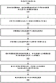
FIG. 5 is a flow diagram that describes a general process 500 of training a depth estimation model in accordance with one or more embodiments. The process 500 produces a plurality of parameters that the depth estimation model 130 may use to generate a depth map given the input image.
Depth estimation training system 170 first acquires 510 training image data comprising a combination of a plurality of monocular temporal images and/or a plurality of stereoscopic image pairs. Monocular video data may be received from a camera on an external device (e.g., camera component 125 on client device 110). The stereoscopic image pair may be received from a pair of binocular cameras on an external device (e.g., camera component 125 on client device 110). In one embodiment, the network interface 105 receives training image data. Depth estimation training system 170 may store training image data in various data repositories, such as a monocular video data repository and a stereoscopic image pair in a stereoscopic image data repository.
When monocular video is used, depth estimation training system 170 groups 520 the multiple temporal images from the monocular video data into multiple sets of three consecutive temporal images. This step of grouping 520 into triplets aims at calculating the photometric reconstruction error using the two temporal images projected onto the third temporal image. In other embodiments, the depth estimation system 170 may group the temporal images into groups of four or five, etc.
The depth estimation training system 170 inputs 530 each image into a depth model to extract depth features. In one embodiment, the image is input into a depth estimation model (e.g., depth estimation model 410) that extracts depth features as a depth map, which may be, for example, the resolution of the image.
The depth estimation training system 170 inputs 540 the images into the pose decoder to extract the pose of each image. In one embodiment, the image is input into a pose estimation model (e.g., pose estimation model 440) that extracts the pose of the image. In embodiments with a depth pose mixture model, a plurality of abstract depth features determined from a depth encoder (e.g., depth encoder 470) are concatenated and input into a pose decoder (e.g., pose decoder 480) to extract a pose for each temporal image. For a stereo image pair, the pose defines or helps define the transformation between the two perspectives of the stereo image pair. In some embodiments, the pose between the two perspectives of a stereoscopic image pair is fixed and/or known. By grouping the monocular video data into multiple sets of three consecutive time images (e.g., first, second, and third time images), the depth estimation training system 170 extracts a relative transformation from first to second, and another relative transformation from second to third.
Using the depth features and pose, the depth estimation training system 170 projects 550 the temporal image onto a subsequent temporal image and/or projects each stereoscopic image onto the other stereoscopic image in the stereoscopic image pair. For the three temporal images in each group, depth estimation training system 170 projects the first temporal image onto a second time step as a first composite frame and projects the third temporal image onto the second time step as a second composite frame. With the depth of the first time image as an intermediate variable, the depth estimation training system 170 projects the first time image onto a second time step based on the pose of the first time image or the relative transformation from the first time image to the second time image. Similarly, with the depth of the third temporal image as an intermediate variable, the depth estimation training system 170 also projects the third temporal image onto the second time step using the inverse relative transform from the second temporal image to the third temporal image. In one embodiment, the image composition module 180 performs a projection from one temporal image to a composite frame. For a stereoscopic image pair, depth estimation training system 170 projects a left image of the stereoscopic image pair onto a right image of the stereoscopic image pair as a right composite frame, and similarly projects from the right image onto the left image as a left composite frame. In one embodiment, the image composition module 180 performs a projection from the left image to the right image and vice versa.
The depth estimation training system 170 calculates 560 a loss value using an input scale occlusion (input scale occlusion) and a motion aware loss function (motion aware loss function) based on a comparison of the synthesized frame and the image. The input proportional occlusion and motion perception loss functions calculate loss values for use in training the depth model. The loss function includes calculating a photometric reconstruction error for each pixel between the synthesized frame and the input image. The loss function may also take into account a minimum photometric reconstruction error between two synthesized frames projected from multiple temporal images of the monocular video, which are temporally adjacent, as described above in the appearance matching loss module 190. The upsampled depth features (by the scaling module 195) may also be used during the generation of the composite frame, which will affect the computation of the appearance matching penalty. The loss function may also implement masking generated by the masking module 197 that reduces static features when calculating the loss value.
The depth estimation training system 170 trains 570 the depth model by minimizing the photometric reconstruction error for each pixel. For a set of three temporal images, the depth estimation training system 170 identifies a minimum photometric reconstruction error for each pixel based on the differences of the first and second synthesized frames and the second temporal image. In another embodiment, the depth estimation training system 170 may define an overall error on the depth estimation model based on the synthesized frames and images. The overall error may be defined as, for example, an average of the photometric reconstruction errors over a pair of images, an average of the photometric reconstruction errors over a number or all of the input images, etc. The depth estimation training system 170 refines the parameters of the depth model while minimizing the photometric reconstruction error (or the overall error). The parameters of the pose model may also be refined as part of minimizing photometric reconstruction errors. In one embodiment, the depth estimation training system 170 computes the photometric reconstruction error as the absolute minimum between the two differences. In one embodiment, the appearance matching loss module 190 minimizes photometric reconstruction errors in tandem with the image synthesis module 180. In another embodiment, the scaling module 195 scales the depth map of the image at varying resolutions to adjust parameters of each layer in the depth model. In another embodiment, the masking module 197 identifies one or more regions having static characteristics and masks these regions when computing the photometric reconstruction error.
Depth estimation model
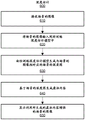
FIG. 6 is a flow diagram that describes a general process 600 for using a depth estimation model in accordance with one or more embodiments. Process 600 generates a depth map for a given input image. Process 600 may be accomplished by a client device having a trained depth estimation model. The client device may be a general purpose computing device or may have a camera. In some embodiments, the client device is implemented in a parallel reality game as described above in FIGS. 1-3. Although described below within the context of a client device, process 600 may be performed on other computing devices.
The method includes receiving 610 an image of a scene. The image of the scene may be captured by a camera that is a component of the client device or external to the client device. In the context of a parallel reality game, a scene may be a real-world location that may be mapped to a virtual location in a virtual world. The image of the scene may also have inherent features that correspond to the geometry of the camera that captured the image. The image may be a single image captured by a camera. Alternatively, the image may be one frame in a video captured by a camera.
The method includes inputting 620 an image of the scene into the trained depth estimation model. The depth estimation system 170 may train the depth estimation model, for example, via the process 500 of fig. 5. The depth estimation model receives an image of a scene and optionally also intrinsic features of the image.
The method includes generating 630 a depth map of the scene corresponding to the image of the scene from the trained depth estimation model. Each pixel of the depth map has a depth value that describes a relative distance of a surface at the corresponding pixel in the image of the scene. Depth estimation receives images of a scene and outputs a depth map based on parameters trained according to fig. 5.
The method includes generating 640 virtual content based on a depth map of a scene. The virtual content may originate from content for a parallel reality game, for example, stored in the game database 115. The generated virtual content may be augmented reality content that may be augmented onto an image of a scene. For example, a virtual character is generated that can move through a scene with knowledge of the depth of the scene. In one example, the size of the avatar may increase as the avatar walks on the street toward the user. In another instance, the virtual character may hide behind the tree, where a portion of the virtual character is then obscured by the tree.
The method includes displaying 650 an image of the scene enhanced with the virtual content. The client device includes an electronic display. The electronic display may provide a constant video captured by the camera with enhanced virtual content.
According to the above example, the parallel reality game may provide interaction with a targeted virtual character. To interact with the virtual character, the user of the mobile device may need to move his mobile device around while keeping the virtual character in the field of view of the camera. As the user moves the mobile device around, the mobile device may continuously capture video or image data that may be used to iteratively generate depth information for the scene as the scene changes as the user moves the mobile device. The mobile device may update the video feed on the display while also updating the avatar based on the generated depth information so that the user perceives the avatar as properly interacting in the scene at all times, e.g., without walking over objects, without having cut-out portions and without any objects obstructing those portions, etc.
Example computing System
FIG. 7 is an example architecture of a computing device according to one embodiment. While FIG. 7 depicts a high-level block diagram that shows physical components of a computer that serves as part or all of one or more entities described herein, according to one embodiment, the computer may have more components, fewer components, or variations of components than provided in FIG. 7. Although FIG. 7 depicts a computer 700, the diagram is intended as a functional description of various features that may be present in a computer system and not as a structural schematic of the implementations described herein. In practice, and as recognized by one of ordinary skill in the art, items shown separately may be combined, and some items may be separated.
At least one processor 702 is shown in fig. 7 coupled to a chipset 704. Memory 706, storage 708, keyboard 710, graphics adapter 712, pointing device 714, and network adapter 716 are also coupled to chipset 704. A display 718 is coupled to the graphics adapter 712. In one embodiment, the functions of the chipset 704 are provided by a memory controller hub 720 and an I/O hub 722. In another embodiment, the memory 706 is coupled directly to the processor 702 rather than the chipset 704. In some embodiments, computer 700 includes one or more communication buses for interconnecting these components. The one or more communication buses optionally include circuitry (sometimes called a chipset) that interconnects and controls communications between system components.
Memory 706 holds instructions and data used by processor 702. Memory 706 may be non-persistent memory, examples of which include high-speed random access memory such as DRAM, SRAM, DDR RAM, ROM, EEPROM, flash memory.
As is known in the art, the computer 700 may have different components than those shown in fig. 7 and/or other components. Additionally, the computer 700 may lack some of the illustrated components. In one embodiment, computer 700, acting as a server, may lack keyboard 710, pointing device 714, graphics adapter 712, and/or display 718. Further, the storage device 708 may be local to the computer 700 and/or remote from the computer 700 (e.g., embodied in a Storage Area Network (SAN)).
As is known in the art, the computer 700 is adapted to execute computer program modules to provide the functionality described herein. As used herein, the term "module" refers to computer program logic for providing the specified functionality. Accordingly, a module may be implemented in hardware, firmware, and/or software. In one embodiment, program modules are stored on the storage device 708, loaded into the memory 706, and executed by the processor 302.
Other considerations
Additional discussion of embodiments can be found in the appendix of the specification entitled "bagging Into Self-Supervised cellular Depth Estimation," which is incorporated herein by reference in its entirety.
Some portions of the above description describe embodiments in terms of algorithmic processes or operations. These algorithmic descriptions and representations are the means used by those skilled in the data processing arts to effectively convey the substance of their work to others skilled in the art. Although described functionally, computationally, or logically, these operations should be understood to be implemented by a computer program comprising instructions for execution by a processor or equivalent electrical circuits, microcode, or the like. Furthermore, it is also convenient, without loss of generality, for these arrangements of functional operations to be sometimes referred to as modules.
As used herein, any reference to "one embodiment" or "an embodiment" means that a particular element, feature, structure, or characteristic described in connection with the embodiment is included in at least one embodiment. The appearances of the phrase "in one embodiment" in various places in the specification are not necessarily all referring to the same embodiment.
Some embodiments may be described using the expression "coupled" and "connected" along with their derivatives. It should be understood that these terms are not intended to be equivalent to each other. For example, some embodiments may be described using the term "connected" to indicate that two or more elements are in direct physical or electrical contact with each other. In another example, some embodiments may be described using the term "coupled" to indicate that two or more elements are in direct physical or electrical contact. The term "coupled," however, may also mean that two or more elements are not in direct contact with each other, but yet still co-operate or interact with each other. The embodiments are not limited in this context.
As used herein, the terms "comprising," "including," "having," or any other variation thereof, are intended to cover a non-exclusive inclusion. For example, a process, method, article, or apparatus that comprises a list of elements is not necessarily limited to only those elements but may include other elements not expressly listed or inherent to such process, method, article, or apparatus. Furthermore, unless expressly stated to the contrary, "or" refers to an inclusive "or" and not to an exclusive "or". For example, either of the following satisfies condition a or B: a is true (or present) and B is false (or not present), a is false (or not present) and B is true (or present), and both a and B are true (or present).
Furthermore, the use of "a" or "an" is used to describe elements and components of embodiments. This is done merely for convenience and to give a general sense of the disclosure. The description should be read to include one or at least one and the singular also includes the plural unless it is clear that it is stated otherwise.
After reading this disclosure, those skilled in the art will appreciate further alternative structural and functional designs of systems and processes for verifying that an account of an online service provider corresponds to a real business. Thus, while particular embodiments and applications have been illustrated and described, it is to be understood that the subject matter described is not limited to the precise construction and components disclosed herein and that various modifications, changes, and variations which will be apparent to those skilled in the art may be made in the arrangement, operation, and details of the disclosed method and apparatus. The scope of protection should be limited only by the attached claims.
Claims (20)
1. A non-transitory computer-readable storage medium storing:
a trained depth model obtained by a process comprising:
acquiring a set of images, the set of images including a first image at a first timestamp, a second image at a second timestamp, and a third image at a third timestamp;
applying the depth model to generate depth maps for the first image and the third image based on parameters of the depth model;
applying the first image and the third image to a pose decoder to generate poses for the first image and the third image;
generating a composite frame based on the depth map and the pose for the first image and the third image, wherein a first composite frame is generated for the second timestamp based on the depth map and the pose for the first image and a second composite frame is generated for the second timestamp based on the depth map and the pose for the third image;
calculating a loss value using an input proportional occlusion perception and motion perception loss function based on a comparison of the composite frame and the second image, wherein calculating the loss value comprises:
calculating a first difference between the first composite frame and the second image and a second difference between the second composite frame and the second image; and
identifying a minimum difference between the first difference and the second difference, wherein the loss value is based on the minimum difference; and
adjusting the parameters of the depth model based on the loss values; and
instructions that, when executed by a computing device, cause the computing device to apply the trained depth model to an image of a scene to generate a depth map of the scene.
2. The non-transitory computer-readable storage medium of claim 1, wherein the set of images comprises a monocular video, each image of the monocular video captured at a corresponding timestamp, wherein generating the composite frame comprises:
for images of the monocular video, composite frames are generated at adjacent timestamps.
3. The non-transitory computer-readable storage medium of claim 2, wherein calculating the first difference and the second difference is part of a process comprising:
for images of the monocular video, the difference between the generated composite frame and the image with the matching timestamp is calculated.
4. The non-transitory computer-readable storage medium of claim 1, wherein:
calculating the first difference and the second difference is part of a process comprising: calculating a first set of differences between the first composite frame and the second image; and the second differences are part of a second set of differences between the second composite frame and the second image; and
identifying the minimum difference is part of a process that includes: for each pixel of the second image, identifying a minimum difference between the first set of differences and the second set of differences, wherein the loss value is based on the minimum difference.
5. The non-transitory computer-readable storage medium of claim 3, wherein calculating the loss value using the input proportional occlusion perception and motion perception loss functions further comprises:
identifying one or more static features in the monocular video,
wherein the loss value is based on filtering out the difference of the one or more static features.
6. The non-transitory computer-readable storage medium of claim 5, wherein identifying one or more static features in the monocular video comprises:
identifying a region in a first image at a first timestamp of the monocular video and in a second image at a second timestamp of the monocular video;
determining whether an object is in a similar position between the first image and the second image; and
defining the region as a static feature in response to determining that the object is in a similar position between the first image and the second image.
7. The non-transitory computer readable storage medium of claim 1, wherein the set of images is at a first resolution and the generated depth map is at a second resolution lower than the first resolution, and wherein the process of obtaining the depth model further comprises:
upsampling the generated depth map from the second resolution to the first resolution.
8. The non-transitory computer-readable storage medium of claim 1, wherein the set of images comprises stereoscopic image pairs, wherein each stereoscopic image pair is captured by a stereoscopic camera pair, wherein generating the composite frame comprises:
for each stereoscopic image pair, a composite frame is generated based on a first image of the stereoscopic image pair.
9. The non-transitory computer-readable storage medium of claim 8, wherein adjusting the parameters of the depth model based on the loss values comprises:
for each stereoscopic image pair, calculating a difference between the generated composite frame and a second image of the stereoscopic image pair; and
adjusting the parameter to minimize the difference.
10. A computer-implemented method, comprising:
receiving an image of a scene;
inputting the image into a trained depth model, the depth model trained with a process comprising:
acquiring a set of images, the set of images including a first image at a first timestamp, a second image at a second timestamp, and a third image at a third timestamp;
inputting the first image and the third image into the depth model to extract a depth map for the first image and the third image based on parameters of the depth model;
inputting the first image and the third image into a pose decoder to extract poses for the first image and the third image;
generating a composite frame based on the depth map and the pose for the first image and the third image, wherein a first composite frame is generated for the second timestamp based on the depth map and the pose for the first image and a second composite frame is generated for the second timestamp based on the depth map and the pose for the third image;
calculating a loss value using an input proportional occlusion perception and motion perception loss function based on a comparison of the composite frame and the second image, wherein calculating the loss value comprises:
calculating a first difference between the first composite frame and the second image and a second difference between the second composite frame and the second image; and
identifying a minimum difference between the first difference and the second difference, wherein the loss value is based on the minimum difference; and
adjusting the parameters of the depth model based on the comparison of the composite frame and the image; and
generating, from the trained model, a depth map of the scene corresponding to the image of the scene.
11. The method of claim 10, wherein the set of images comprises a monocular video, wherein each image of the monocular video is captured at a corresponding timestamp, wherein generating the composite frame comprises:
for images of the monocular video, composite frames are generated at adjacent timestamps.
12. The method of claim 11, wherein calculating the first difference and the second difference is part of a process comprising:
for images of the monocular video, a difference between the generated composite frame and the image with the matching timestamp is calculated.
13. The method of claim 10, wherein:
calculating the first difference and the second difference is part of a process comprising: calculating a first set of differences between the first composite frame and the second image; and the second difference is part of a second set of differences between the second composite frame and the second image; and
identifying the minimum difference is part of a process that includes: for each pixel of the second image, identifying a minimum difference between the first set of differences and the second set of differences, wherein the loss value is based on the minimum difference.
14. The method of claim 12, wherein calculating the loss value using the input proportional occlusion perception and motion perception loss functions further comprises:
identifying one or more static features in the monocular video, wherein the loss value is based on filtering out the difference of the one or more static features.
15. The method of claim 14, wherein identifying one or more static features in the monocular video comprises:
identifying a region in a first image at a first timestamp of the monocular video and in a second image at a second timestamp of the monocular video;
determining whether an object is in a similar position between the first image and the second image; and
defining the region as a static feature in response to determining that the object is in a similar position between the first image and the second image.
16. The method of claim 10, wherein the set of images is at a first resolution and the extracted depth map is at a second resolution lower than the first resolution, the process for training the depth model further comprising:
upsampling the extracted depth map from the second resolution to the first resolution.
17. The method of claim 10, wherein the set of images comprises stereoscopic image pairs, wherein each stereoscopic image pair is captured by a stereoscopic camera pair, wherein generating the composite frame comprises:
for each stereoscopic image pair, a composite frame is generated based on a first image of the stereoscopic image pair.
18. The method of claim 17, wherein adjusting the parameters of the depth model based on the loss values comprises:
for each stereoscopic image pair, calculating a difference between the generated composite frame and a second image of the stereoscopic image pair; and
adjusting the parameter to minimize the difference.
19. The method of claim 10, further comprising:
displaying the image of the scene augmented with virtual content based on the depth map of the scene.
20. A non-transitory computer-readable storage medium having instructions stored thereon, which, when executed by a computing device, cause the computing device to perform operations comprising:
receiving an image of a scene;
inputting the image into a trained depth model, the depth model trained with a process comprising:
acquiring a set of images, the set of images including a first image at a first timestamp, a second image at a second timestamp, and a third image at a third timestamp;
inputting the first image and the third image into a depth encoder to extract abstract depth features for the first image and the third image based on parameters of the depth encoder;
concatenating the abstract depth features for the first image and the third image;
inputting the concatenated abstract depth features into a pose decoder to extract poses for the first image and the third image;
generating a composite frame based on parameters of the model and the poses for the first image and the third image, wherein a first composite frame is generated for the second timestamp based on a depth map and pose for the first image and a second composite frame is generated for the second timestamp based on a depth map and pose for the third image;
calculating a loss value using an input proportional occlusion perception and motion perception loss function based on a comparison of the composite frame and the second image, wherein calculating the loss value comprises:
calculating a first difference between the first composite frame and the second image and a second difference between the second composite frame and the second image;
identifying a minimum difference between the first difference and the second difference, wherein the loss value is based on the minimum difference; and
adjusting the parameters of the model based on a comparison of the composite frame and the image; and
generating, from the trained model, a depth map of the scene corresponding to the image of the scene.
Applications Claiming Priority (3)
| Application Number | Priority Date | Filing Date | Title |
|---|---|---|---|
| US201862673045P | 2018-05-17 | 2018-05-17 | |
| US62/673,045 | 2018-05-17 | ||
| PCT/US2019/032616 WO2019222467A1 (en) | 2018-05-17 | 2019-05-16 | Self-supervised training of a depth estimation system |
Publications (2)
| Publication Number | Publication Date |
|---|---|
| CN112534475A CN112534475A (en) | 2021-03-19 |
| CN112534475B true CN112534475B (en) | 2023-01-10 |
Family
ID=68533243
Family Applications (1)
| Application Number | Title | Priority Date | Filing Date |
|---|---|---|---|
| CN201980047649.XA Active CN112534475B (en) | 2018-05-17 | 2019-05-16 | Self-supervised training of depth estimation systems |
Country Status (9)
| Country | Link |
|---|---|
| US (2) | US11082681B2 (en) |
| EP (1) | EP3794555B1 (en) |
| JP (1) | JP7241775B2 (en) |
| KR (1) | KR102506959B1 (en) |
| CN (1) | CN112534475B (en) |
| AU (1) | AU2019270095A1 (en) |
| CA (1) | CA3100640C (en) |
| TW (1) | TWI790380B (en) |
| WO (1) | WO2019222467A1 (en) |
Families Citing this family (45)
| Publication number | Priority date | Publication date | Assignee | Title |
|---|---|---|---|---|
| AU2019270095A1 (en) * | 2018-05-17 | 2021-01-14 | Niantic, Inc. | Self-supervised training of a depth estimation system |
| JP2020042665A (en) * | 2018-09-12 | 2020-03-19 | キヤノン株式会社 | Information processing apparatus, control method thereof, and program |
| US20200137380A1 (en) * | 2018-10-31 | 2020-04-30 | Intel Corporation | Multi-plane display image synthesis mechanism |
| US20200202622A1 (en) * | 2018-12-19 | 2020-06-25 | Nvidia Corporation | Mesh reconstruction using data-driven priors |
| US11138751B2 (en) * | 2019-07-06 | 2021-10-05 | Toyota Research Institute, Inc. | Systems and methods for semi-supervised training using reprojected distance loss |
| US10762650B1 (en) * | 2019-09-13 | 2020-09-01 | Toyota Motor Engineering & Manufacturing North America, Inc. | System and method for estimating depth using a monocular camera |
| US11210802B2 (en) * | 2019-09-24 | 2021-12-28 | Toyota Research Institute, Inc. | Systems and methods for conditioning training data to avoid learned aberrations |
| US11348375B2 (en) | 2019-10-15 | 2022-05-31 | Assa Abloy Ab | Systems and methods for using focal stacks for image-based spoof detection |
| US11294996B2 (en) | 2019-10-15 | 2022-04-05 | Assa Abloy Ab | Systems and methods for using machine learning for image-based spoof detection |
| EP3822913A1 (en) * | 2019-11-14 | 2021-05-19 | Continental Automotive GmbH | Spatial aware object detection by flash lidar and camera fusion based super-resolution |
| CN111179326B (en) * | 2019-12-27 | 2020-12-29 | 精英数智科技股份有限公司 | Monocular depth estimation method, system, equipment and storage medium |
| WO2021150016A1 (en) | 2020-01-20 | 2021-07-29 | Samsung Electronics Co., Ltd. | Methods and systems for performing tasks on media using attribute specific joint learning |
| WO2021154099A1 (en) * | 2020-01-30 | 2021-08-05 | Weta Digital Limited | System for image compositing including training with synthetic data |
| US11710247B2 (en) | 2020-01-30 | 2023-07-25 | Unity Technologies Sf | System for image compositing including training with synthetic data |
| US11503266B2 (en) | 2020-03-06 | 2022-11-15 | Samsung Electronics Co., Ltd. | Super-resolution depth map generation for multi-camera or other environments |
| CN113572919B (en) * | 2020-04-29 | 2023-06-30 | 思特威(上海)电子科技股份有限公司 | Rapid automatic exposure adjusting method and binocular system |
| CN113592875B (en) * | 2020-04-30 | 2024-01-23 | 阿里巴巴集团控股有限公司 | Data processing method, image processing method, storage medium, and computing device |
| US11341719B2 (en) * | 2020-05-07 | 2022-05-24 | Toyota Research Institute, Inc. | System and method for estimating depth uncertainty for self-supervised 3D reconstruction |
| TWI772806B (en) * | 2020-05-22 | 2022-08-01 | 國立陽明交通大學 | System and method for scene understanding |
| CN111709890B (en) * | 2020-06-12 | 2023-11-24 | 北京小米松果电子有限公司 | Training method and device for image enhancement model and storage medium |
| US11257231B2 (en) * | 2020-06-17 | 2022-02-22 | Toyota Research Institute, Inc. | Camera agnostic depth network |
| US11321859B2 (en) * | 2020-06-22 | 2022-05-03 | Toyota Research Institute, Inc. | Pixel-wise residual pose estimation for monocular depth estimation |
| US11275959B2 (en) | 2020-07-07 | 2022-03-15 | Assa Abloy Ab | Systems and methods for enrollment in a multispectral stereo facial recognition system |
| CN111881804B (en) * | 2020-07-22 | 2023-07-28 | 汇纳科技股份有限公司 | Posture estimation model training method, system, medium and terminal based on joint training |
| CN111768438B (en) * | 2020-07-30 | 2023-11-24 | 腾讯科技(深圳)有限公司 | Image processing method, device, equipment and computer readable storage medium |
| CN114077310B (en) | 2020-08-14 | 2023-08-25 | 宏达国际电子股份有限公司 | Method and system for providing virtual environment and non-transient computer readable storage medium |
| JP7379299B2 (en) * | 2020-08-28 | 2023-11-14 | 株式会社東芝 | Position and orientation estimation device, position and orientation estimation method, and program |
| CN114170290A (en) * | 2020-09-10 | 2022-03-11 | 华为技术有限公司 | Image processing method and related equipment |
| KR102472568B1 (en) * | 2020-10-15 | 2022-12-01 | 한국전자기술연구원 | Apparatus for constructing a 3D map for providing augmented reality based on pose information and depth information, and a method therefor |
| KR102525583B1 (en) * | 2020-10-15 | 2023-04-26 | 한국전자기술연구원 | Apparatus for generating 3D map using stereo frame of lightweight augmented reality device and method therefor |
| US11868439B2 (en) * | 2020-11-13 | 2024-01-09 | Toyota Research Institute, Inc. | Mixed-batch training of a multi-task network |
| US11734855B2 (en) * | 2020-11-20 | 2023-08-22 | Kabushiki Kaisha Toshiba | Rotation equivariant orientation estimation for omnidirectional localization |
| WO2022123452A1 (en) * | 2020-12-12 | 2022-06-16 | Niantic, Inc. | Self-supervised multi-frame monocular depth estimation model |
| KR20220085481A (en) | 2020-12-15 | 2022-06-22 | 삼성전자주식회사 | Method and apparatus of image processing |
| KR102236240B1 (en) * | 2021-02-15 | 2021-04-05 | 주식회사 삼인공간정보 | Device for converting terrain shape files |
| US11688090B2 (en) * | 2021-03-16 | 2023-06-27 | Toyota Research Institute, Inc. | Shared median-scaling metric for multi-camera self-supervised depth evaluation |
| CN113160294B (en) * | 2021-03-31 | 2022-12-23 | 中国科学院深圳先进技术研究院 | Image scene depth estimation method and device, terminal equipment and storage medium |
| CN113470097B (en) * | 2021-05-28 | 2023-11-24 | 浙江大学 | Monocular video depth estimation method based on time domain correlation and gesture attention |
| KR102489890B1 (en) * | 2021-05-28 | 2023-01-17 | 한국항공대학교산학협력단 | Depth estimation system and depth estimation method |
| CN113591823B (en) * | 2021-10-08 | 2022-03-25 | 北京的卢深视科技有限公司 | Depth prediction model training and face depth image generation method and device |
| KR102559936B1 (en) * | 2022-01-28 | 2023-07-27 | 포티투닷 주식회사 | Method and apparatus of estimating depth information using monocular camera |
| CN114549612A (en) * | 2022-02-25 | 2022-05-27 | 北京百度网讯科技有限公司 | Model training and image processing method, device, equipment and storage medium |
| US20230328216A1 (en) * | 2022-04-06 | 2023-10-12 | Samsung Electronics Co., Ltd. | Encoding Depth Information for Images |
| CN114998411B (en) * | 2022-04-29 | 2024-01-09 | 中国科学院上海微系统与信息技术研究所 | Self-supervision monocular depth estimation method and device combining space-time enhancement luminosity loss |
| CN117115786B (en) * | 2023-10-23 | 2024-01-26 | 青岛哈尔滨工程大学创新发展中心 | Depth estimation model training method for joint segmentation tracking and application method |
Citations (2)
| Publication number | Priority date | Publication date | Assignee | Title |
|---|---|---|---|---|
| JP2015087851A (en) * | 2013-10-29 | 2015-05-07 | 日本電信電話株式会社 | Image processor and image processing program |
| CN107438866A (en) * | 2015-05-13 | 2017-12-05 | 谷歌公司 | Depth is three-dimensional:Study predicts new view from real world image |
Family Cites Families (16)
| Publication number | Priority date | Publication date | Assignee | Title |
|---|---|---|---|---|
| CN102223553B (en) | 2011-05-27 | 2013-03-20 | 山东大学 | Method for converting two-dimensional video into three-dimensional video automatically |
| US20130077820A1 (en) * | 2011-09-26 | 2013-03-28 | Microsoft Corporation | Machine learning gesture detection |
| US10262462B2 (en) * | 2014-04-18 | 2019-04-16 | Magic Leap, Inc. | Systems and methods for augmented and virtual reality |
| JP2017129904A (en) | 2016-01-18 | 2017-07-27 | ソニー株式会社 | Information processor, information processing method, and record medium |
| US10255522B2 (en) * | 2016-06-17 | 2019-04-09 | Facebook, Inc. | Generating object proposals using deep-learning models |
| IL281241B (en) * | 2016-08-22 | 2022-08-01 | Magic Leap Inc | Augmented reality display device with deep learning sensors |
| GB2553782B (en) | 2016-09-12 | 2021-10-20 | Niantic Inc | Predicting depth from image data using a statistical model |
| CN107067465A (en) | 2017-04-14 | 2017-08-18 | 深圳市唯特视科技有限公司 | A kind of 3-D view synthetic method that network is generated based on checking transition diagram picture |
| CN107578436B (en) * | 2017-08-02 | 2020-06-12 | 南京邮电大学 | Monocular image depth estimation method based on full convolution neural network FCN |
| CN107767413B (en) * | 2017-09-20 | 2020-02-18 | 华南理工大学 | Image depth estimation method based on convolutional neural network |
| US10803546B2 (en) * | 2017-11-03 | 2020-10-13 | Baidu Usa Llc | Systems and methods for unsupervised learning of geometry from images using depth-normal consistency |
| CN111386550A (en) * | 2017-11-15 | 2020-07-07 | 谷歌有限责任公司 | Unsupervised learning of image depth and ego-motion predictive neural networks |
| CN107909150B (en) | 2017-11-29 | 2020-08-18 | 华中科技大学 | Method and system for on-line training CNN based on block-by-block random gradient descent method |
| CN110574371B (en) * | 2017-12-08 | 2021-12-21 | 百度时代网络技术(北京)有限公司 | Stereo camera depth determination using hardware accelerators |
| US10810754B2 (en) * | 2018-04-24 | 2020-10-20 | Ford Global Technologies, Llc | Simultaneous localization and mapping constraints in generative adversarial networks for monocular depth estimation |
| AU2019270095A1 (en) * | 2018-05-17 | 2021-01-14 | Niantic, Inc. | Self-supervised training of a depth estimation system |
-
2019
- 2019-05-16 AU AU2019270095A patent/AU2019270095A1/en active Pending
- 2019-05-16 CN CN201980047649.XA patent/CN112534475B/en active Active
- 2019-05-16 WO PCT/US2019/032616 patent/WO2019222467A1/en active Application Filing
- 2019-05-16 KR KR1020207036300A patent/KR102506959B1/en active IP Right Grant
- 2019-05-16 CA CA3100640A patent/CA3100640C/en active Active
- 2019-05-16 JP JP2020564565A patent/JP7241775B2/en active Active
- 2019-05-16 EP EP19802580.1A patent/EP3794555B1/en active Active
- 2019-05-16 US US16/413,907 patent/US11082681B2/en active Active
- 2019-05-17 TW TW108117215A patent/TWI790380B/en active
-
2021
- 2021-06-22 US US17/354,517 patent/US20210314550A1/en active Pending
Patent Citations (2)
| Publication number | Priority date | Publication date | Assignee | Title |
|---|---|---|---|---|
| JP2015087851A (en) * | 2013-10-29 | 2015-05-07 | 日本電信電話株式会社 | Image processor and image processing program |
| CN107438866A (en) * | 2015-05-13 | 2017-12-05 | 谷歌公司 | Depth is three-dimensional:Study predicts new view from real world image |
Non-Patent Citations (1)
| Title |
|---|
| Unsupervised Learning of Depth and Ego-Motion from Video";Tinghui Zhou 等;《2017 IEEE Conference on Computer Vision and Pattern Recognition (CVPR)》;20171109;摘要,第2-3,5节 * |
Also Published As
| Publication number | Publication date |
|---|---|
| CA3100640A1 (en) | 2019-11-21 |
| TW202004670A (en) | 2020-01-16 |
| CN112534475A (en) | 2021-03-19 |
| US20210314550A1 (en) | 2021-10-07 |
| WO2019222467A1 (en) | 2019-11-21 |
| EP3794555A1 (en) | 2021-03-24 |
| JP7241775B2 (en) | 2023-03-17 |
| US20190356905A1 (en) | 2019-11-21 |
| TWI790380B (en) | 2023-01-21 |
| KR102506959B1 (en) | 2023-03-07 |
| EP3794555B1 (en) | 2024-03-13 |
| AU2019270095A1 (en) | 2021-01-14 |
| US11082681B2 (en) | 2021-08-03 |
| WO2019222467A8 (en) | 2020-03-26 |
| CA3100640C (en) | 2023-04-18 |
| EP3794555A4 (en) | 2021-06-09 |
| JP2021526680A (en) | 2021-10-07 |
| KR20200146040A (en) | 2020-12-31 |
Similar Documents
| Publication | Publication Date | Title |
|---|---|---|
| CN112534475B (en) | Self-supervised training of depth estimation systems | |
| JP7174139B2 (en) | Self-supervised Training of Depth Estimation Models with Depth Hints | |
| US20230196690A1 (en) | High-Speed Real-Time Scene Reconstruction from Input Image Data | |
| AU2021235397B2 (en) | Determining traversable space from single images | |
| TWI839513B (en) | Computer-implemented method and non-transitory computer-readable storage medium for self-supervised training of a depth estimation model using depth hints | |
| TWI829167B (en) | Method and non-transitory computer-readable storage medium for image depth prediction with wavelet decomposition |
Legal Events
| Date | Code | Title | Description |
|---|---|---|---|
| PB01 | Publication | ||
| PB01 | Publication | ||
| SE01 | Entry into force of request for substantive examination | ||
| SE01 | Entry into force of request for substantive examination | ||
| GR01 | Patent grant | ||
| GR01 | Patent grant |