CN112515394A - Bar chair - Google Patents
Bar chair Download PDFInfo
- Publication number
- CN112515394A CN112515394A CN202011387432.4A CN202011387432A CN112515394A CN 112515394 A CN112515394 A CN 112515394A CN 202011387432 A CN202011387432 A CN 202011387432A CN 112515394 A CN112515394 A CN 112515394A
- Authority
- CN
- China
- Prior art keywords
- thick bamboo
- groove
- limiting plate
- mounting cylinder
- bar chair
- Prior art date
- Legal status (The legal status is an assumption and is not a legal conclusion. Google has not performed a legal analysis and makes no representation as to the accuracy of the status listed.)
- Granted
Links
- 238000009434 installation Methods 0.000 claims abstract description 52
- 235000017166 Bambusa arundinacea Nutrition 0.000 claims abstract description 48
- 235000017491 Bambusa tulda Nutrition 0.000 claims abstract description 48
- 241001330002 Bambuseae Species 0.000 claims abstract description 48
- 235000015334 Phyllostachys viridis Nutrition 0.000 claims abstract description 48
- 239000011425 bamboo Substances 0.000 claims abstract description 48
- 230000005489 elastic deformation Effects 0.000 claims abstract description 4
- 238000007789 sealing Methods 0.000 claims description 10
- 210000002421 cell wall Anatomy 0.000 claims description 2
- 230000000694 effects Effects 0.000 abstract description 18
- 239000000872 buffer Substances 0.000 description 4
- 230000029058 respiratory gaseous exchange Effects 0.000 description 4
- ZZUFCTLCJUWOSV-UHFFFAOYSA-N furosemide Chemical compound C1=C(Cl)C(S(=O)(=O)N)=CC(C(O)=O)=C1NCC1=CC=CO1 ZZUFCTLCJUWOSV-UHFFFAOYSA-N 0.000 description 2
- 230000002265 prevention Effects 0.000 description 2
- 230000000087 stabilizing effect Effects 0.000 description 2
- 244000269722 Thea sinensis Species 0.000 description 1
- 230000009286 beneficial effect Effects 0.000 description 1
- 239000002537 cosmetic Substances 0.000 description 1
- 230000002452 interceptive effect Effects 0.000 description 1
Images


Classifications
-
- A—HUMAN NECESSITIES
- A47—FURNITURE; DOMESTIC ARTICLES OR APPLIANCES; COFFEE MILLS; SPICE MILLS; SUCTION CLEANERS IN GENERAL
- A47C—CHAIRS; SOFAS; BEDS
- A47C9/00—Stools for specified purposes
- A47C9/007—High stools, e.g. bar stools
-
- A—HUMAN NECESSITIES
- A47—FURNITURE; DOMESTIC ARTICLES OR APPLIANCES; COFFEE MILLS; SPICE MILLS; SUCTION CLEANERS IN GENERAL
- A47C—CHAIRS; SOFAS; BEDS
- A47C7/00—Parts, details, or accessories of chairs or stools
- A47C7/002—Chair or stool bases
- A47C7/004—Chair or stool bases for chairs or stools with central column, e.g. office chairs
-
- A—HUMAN NECESSITIES
- A47—FURNITURE; DOMESTIC ARTICLES OR APPLIANCES; COFFEE MILLS; SPICE MILLS; SUCTION CLEANERS IN GENERAL
- A47C—CHAIRS; SOFAS; BEDS
- A47C7/00—Parts, details, or accessories of chairs or stools
- A47C7/02—Seat parts
- A47C7/14—Seat parts of adjustable shape; elastically mounted ; adaptable to a user contour or ergonomic seating positions
Abstract
The utility model belongs to the technical field of the seat and specifically relates to a bar chair is related to, it is including placing base, a support section of thick bamboo, seat support subaerial, the vertical fixed setting of a support section of thick bamboo is on the base, vertical grafting has a first installation section of thick bamboo and a second installation section of thick bamboo in the support section of thick bamboo, a first installation section of thick bamboo is pegged graft in a second installation section of thick bamboo, the fixed first touch panel that supports that is provided with of a first installation section of thick bamboo downside, be provided with first limiting plate in the second installation section of thick bamboo, first limiting plate is contradicted at the downside of first touch panel, first groove of stepping down has been seted up on the first touch panel, it is provided with first reset spring to be connected between the downside of first touch panel and the second installation section of thick bamboo, when first limiting plate passed first groove of stepping down, elastic deformation takes place for reset. This application has the effect of adjusting the bar chair softness and hardness.
Description
Technical Field
The application relates to the field of seats, in particular to a bar chair.
Background
The bar chair is mainly used in a bar at first, is increasingly used in rinsing bars, fast restaurants, tea restaurants, coffee shops, jewelry stores, cosmetics stores and the like, and represents passion, fashion and popularity.
A bar chair that is now common includes base, seat support, support column, and the base is placed subaerial, and the vertical setting of support column is on the base, and the placing of supporting seat can be stabilized to the base, has seted up the standing groove in the support column, and the tank bottom of standing groove is provided with reset spring, and vertical grafting is provided with the carriage release lever in the standing groove, and the lower extreme of carriage release lever is fixed to be set up on reset spring, and the fixed upper end that sets up at the carriage release lever of base. The people sits on the seat support, and the reset spring is arranged to buffer the seat support, so that the hardness of the bar chair is reduced, and the comfort level of the people sitting on the bar chair is improved.
In view of the above-mentioned related art, the inventor believes that there is a drawback in that the degree of softness of the bar chair cannot be adjusted.
Disclosure of Invention
In order to adjust the hardness of the bar chair, the bar chair provided by the application adopts the following technical scheme:
the utility model provides a bar chair, is including placing base, a supporting cylinder, the seat support subaerial, the vertical fixed setting of a supporting cylinder is on the base, vertical grafting has first installation section of thick bamboo and second installation section of thick bamboo in the supporting cylinder, first installation section of thick bamboo is pegged graft in the second installation section of thick bamboo, the fixed first touch panel that supports that is provided with of first installation section of thick bamboo downside, be provided with first limiting plate in the second installation section of thick bamboo, first limiting plate is contradicted at the downside of first touch panel, first groove of stepping down has been seted up on the first touch panel, it is provided with first reset spring to be connected between the downside of first touch panel and the second installation section of thick bamboo, when first limiting plate passed first groove of stepping down, reset spring takes place elastic deformation.
Through adopting above-mentioned technical scheme, when first touch panel contacted with first limiting plate, a first installation section of thick bamboo was in rigid state, rotated a first installation section of thick bamboo, let a first limiting plate through the first groove of stepping down, a conflict board downside extrudees first reset spring, cushions a first installation section of thick bamboo, reaches the effect of adjusting the bar chair soft or hard.
Preferably, the downside of a second installation section of thick bamboo is fixed and is provided with the second and supports the touch panel, be provided with second reset spring between the second and the bobbin base of a support section of thick bamboo, the fixed second limiting plate that is provided with on the inboard lateral wall of a support section of thick bamboo, the second has been supported and has been seted up the second groove of stepping down on the touch panel, when the second limiting plate passed the second groove of stepping down, elastic deformation took place for second reset spring.
Through adopting above-mentioned technical scheme, rotate a second installation section of thick bamboo, let the second limiting plate pass the second groove of stepping down, the second is supported the touch panel and is extruded second reset spring, cushions a second installation section of thick bamboo, reaches the effect of further adjusting the bar chair soft or hard.
Preferably, the lower side of the first contact plate is vertically and rotatably provided with a first connecting rod, and the lower end of the first connecting rod is fixedly connected to a first return spring.
Through adopting above-mentioned technical scheme, when first conflict board rotated, first connecting rod rotation setting that comes can reduce first reset spring to the interference of first conflict board, reached the effect of stabilizing first conflict board.
Preferably, the fixed first guide block that is provided with on the lateral wall of a second installation section of thick bamboo, first spacing groove has been seted up on the lateral wall of first touch panel, first guide block is arranged in first spacing groove, when first spacing groove and first guide block contact, first limiting plate can pass first groove of stepping down.
Through adopting above-mentioned technical scheme, when first conflict board rotated, when the cell wall in the first groove of stepping down contacted with first guide block, first limiting plate was located the first below in the groove of stepping down, made things convenient for first limiting plate through the groove of stepping down, reached the effect that makes things convenient for first installation section of thick bamboo to extrude first reset spring.
Preferably, a plurality of placing grooves are vertically and upwards formed in the lower side of the base, an air suction disc is fixedly arranged in each placing groove, a yielding port is formed in each placing groove, a moving rod is movably arranged in each yielding port, a pull rope is arranged on each first mounting cylinder, and the end part of each pull rope is fixedly connected to the corresponding moving rod.
Through adopting above-mentioned technical scheme, when first installation section of thick bamboo moved down, can stimulate the carriage release lever and remove, the dish downside of breathing in and ground contact to let the dish of breathing in form the negative pressure, let the dish of breathing in suck ground, reach the effect that reduces the base and remove.
Preferably, the first mounting cylinder is provided with a rotating ring in a rotating manner, and the pull rope is fixedly connected to the rotating ring.
Through adopting above-mentioned technical scheme, when a first installation section of thick bamboo rotated, the stay cord was connected on the swivel becket, can reduce the interference of stay cord to a first installation section of thick bamboo, reached and stabilized a first installation section of thick bamboo pivoted effect.
Preferably, the moving rod is fixedly provided with a falling-off prevention ring, and the falling-off prevention ring is abutted against the inner side wall of the air suction disc.
Through adopting above-mentioned technical scheme, the carriage release lever removes when wanting to break away from and lets a mouthful, and anticreep ring is contradicted on letting a mouthful, reaches the effect that prevents the carriage release lever and break away from.
Preferably, a sealing layer is fixedly arranged on the opening wall of the relief opening.
Through adopting above-mentioned technical scheme, when the carriage release lever removed, the sealing layer can let the dish of breathing in keep airtight with ground, reaches the effect that increases the leakproofness of letting the position mouth.
In summary, the present application includes at least one of the following beneficial technical effects: first conflict board downside extrudees first reset spring, cushions a first installation section of thick bamboo, and second conflict board downside extrudees a second reset spring simultaneously, cushions a second installation section of thick bamboo, reaches the effect of adjusting the bar chair soft or hard.
Drawings
Fig. 1 is a schematic view of the overall structure of the bar chair in the present embodiment.
Fig. 2 is a schematic view of the mounting structure of the first mounting cylinder in this embodiment.
Fig. 3 is a schematic structural view of the first mounting cylinder pressing the first return spring in the present embodiment.
Fig. 4 is a schematic view of the mounting structure of the second mounting cylinder in this embodiment.
Fig. 5 is a schematic structural view of the second mounting cylinder pressing the second return spring in the present embodiment.
FIG. 6 is a schematic view of the mounting structure of the suction plate in this embodiment.
FIG. 7 is a schematic view of the structure of the getter disk in this embodiment.
Fig. 8 is a schematic structural view of the moving rod moving towards the end far away from the ground in the embodiment.
Description of reference numerals: 1. a base; 2. a chair seat; 3. a support cylinder; 4. a first mounting cylinder; 5. a second mounting cylinder; 6. pulling a rope; 7. a rotating ring; 8. a limiting ring; 9. a first abdicating groove; 10. a first limit plate; 11. a first limit groove; 12. a first guide block; 13. a first contact end; 14. a first return spring; 15. a second limit groove; 16. a second touch panel; 17. a second abdicating groove; 18. a first touch panel; 19. a second limiting plate; 20. a wire lumen; 21. a second guide block; 22. a second contact end; 23. the anti-drop ring; 24. a placement groove; 25. a suction plate; 26. a travel bar; 27. a sealing layer; 28. a let position port; 29. a first connecting rod; 30. a second connecting rod; 31. a second return spring.
Detailed Description
The present application is described in further detail below with reference to figures 1-8.
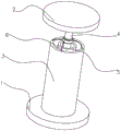
The embodiment of the application discloses a bar chair, referring to fig. 1, including placing base 1, a support section of thick bamboo 3, seat support 2 subaerial, support 3 vertical fixed settings on base 1, base 1 is discoid, and seat support 2 also is discoid, and base 1 can support a support section of thick bamboo 3, lets the stable placing of a support section of thick bamboo 3.
Referring to fig. 2, specifically, a first mounting cylinder 4 and a second mounting cylinder 5 are vertically inserted into the supporting cylinder 3, the first mounting cylinder 4 is inserted into the second mounting cylinder 5, the upper end of the first mounting cylinder 4 is located outside the second mounting cylinder 5, and the lower surface of the seat 2 is fixedly arranged at the upper end of the first mounting cylinder 4. A first contact plate 18 is fixedly arranged on the lower side of the first installation cylinder 4, the first contact plate 18 and the first installation cylinder 4 are integrally formed, the first contact plate 18 in the embodiment is a circular plate, a first yielding groove 9 is vertically formed in the first contact plate 18, and a first limiting plate 10 is fixedly arranged on the side wall of the second installation cylinder 5.
Referring to fig. 2 and 3, specifically, the upper surface of the first limiting plate 10 contacts with the lower surface of the first contact plate 18 to support the first mounting cylinder 4, the first mounting cylinder 4 can rotate in the second mounting cylinder 5, when the first abdicating groove 9 rotates to the upper side of the first limiting plate 10, the first mounting cylinder 4 can move down, and the first limiting plate 10 can pass through the first abdicating groove 9. The lower surface of the first abutting plate 18 is rotatably provided with a first connecting rod 29, the lower side of the second mounting cylinder 5 is fixedly connected with a second abutting plate 16, and the second abutting plate 16 and the second connecting cylinder are integrally formed.
Referring to fig. 2 and 3, in particular, a first return spring 14 is connected between the first connecting rod 29 and the second abutting plate 16, and when the first limiting plate 10 passes through the first avoiding groove 9, the first abutting plate 18 can abut against the first return spring 14. When a hard bar chair needs to be seated, the first limiting plate 10 is in contact with the first touch plate 18, the first limiting plate 10 supports the first limiting plate 10, and the first mounting cylinder 4 cannot move downwards. The soft or hard of bar chair need be adjusted, when letting seat support 2 have elasticity, rotatable first installation section of thick bamboo 4 lets first limiting plate 10 pass first groove of stepping down 9, and first contact plate 18 and first reset spring 14 contact are supported, and first reset spring 14 cushions first contact plate 18 to let seat support 2 have certain elasticity, reach the effect of adjusting the soft or hard of bar chair.
Referring to fig. 4 and 5, specifically, the lower end of the support cylinder 3 is integrally formed with the base 1, a second connecting rod 30 is rotatably disposed on the lower surface of the second contact plate 16, and a second return spring 31 is fixedly connected between the second connecting rod 30 and the bottom plate. The second limiting plate 19 is fixedly arranged on the inner side wall of the supporting cylinder 3, and when the second mounting cylinder 5 does not move downwards, the second limiting plate 19 can support the second contact plate 16 to prevent the second mounting cylinder 5 from moving downwards. The second contact plate 16 is provided with a second yielding groove 17, when the second mounting tube 5 is rotated, the second limiting plate 19 can pass through the second yielding groove 17, the second contact plate 16 is contacted with the second return spring 31, and the second return spring 31 can buffer the second contact plate 16.
Referring to fig. 4 and 5, specifically, when the elasticity of the chair seat 2 needs to be further increased, the second mounting cylinder 5 is rotated when the first abutting plate 18 extrudes the first return spring 14, the second abutting plate 16 extrudes the second return spring 31, the first return spring 14 and the second return spring 31 buffer the chair seat 2 at the same time, the elasticity of the chair seat 2 is improved, and the effect of further adjusting the softness and hardness of the bar chair is achieved.
Referring to fig. 2 and 3, specifically, a first guide block 12 is vertically and fixedly arranged on the inner side wall of the second mounting cylinder 5, a first limit groove 11 is formed in the side wall of the first contact plate 18, the first limit groove 11 is an arc-shaped groove, the first guide block 12 is located in the first limit groove 11, and the first guide block 12 is smaller than the first limit groove 11.
Referring to fig. 2 and 3, specifically, the first limiting groove 11 includes a first yielding end, when the first yielding end contacts with the side wall of the first guide block 12, the first limiting plate 10 is located below the first yielding groove 9, and when the first yielding end does not contact with the first guide block 12, the first limiting plate 10 abuts against the first contact plate 18. When the first installation section of thick bamboo 4 rotated, when first letting the position end and the contact of first guide block 12, first limiting plate 10 passed first groove 9 of stepping down, conveniently controlled first installation section of thick bamboo 4 pivoted distance, reached the effect of conveniently adjusting the bar chair.
Referring to fig. 4 and 5, specifically, a second guide block 21 is vertically and fixedly arranged on the inner side wall of the support cylinder 3, a second limit groove 15 is formed in the side wall of the second contact plate 16, the second limit groove 15 is an arc-shaped groove, the second guide block 21 is located in the second limit groove 15, and the second guide block 21 is smaller than the second limit groove 15. The second limiting groove 15 includes a second yielding end, when the second yielding end contacts with the side wall of the second guide block 21, the second limiting plate 19 is located below the second yielding groove 17, and when the second yielding end does not contact with the second guide block 21, the second limiting plate 19 abuts against the second abutting plate 16. When the second installation section of thick bamboo 5 rotated, when the second let a position end and the contact of second guide block 21, the second limiting plate 19 passed the second groove 17 of stepping down, conveniently controlled second installation section of thick bamboo 5 pivoted distance, reached the effect of conveniently adjusting the bar chair.
Referring to fig. 3 and 5, specifically, when the first installation cylinder 4 rotates, the first abutting end 13 abuts against the first guide block 12, the first installation cylinder 4 can be continuously rotated to drive the second abutting end 22 to abut against the second guide block 21, and only by controlling the first installation cylinder 4, the first abutting plate 18 and the first return spring 14 can be controlled to contact, and the second abutting plate 16 and the second return spring 31 can be controlled to contact, so that the effect of conveniently controlling the bar chair can be achieved.
Referring to fig. 6 and 7, specifically, a plurality of placing grooves 24 are vertically and upwardly formed in the lower side of the base 1, a suction disc 25 is fixedly disposed in the placing grooves 24, the suction disc 25 in this embodiment is a rubber suction disc 25, and the suction disc 25 is downwardly opened and contacts with the ground. The air suction disc 25 is provided with a relief opening 28, the relief opening 28 is fixedly provided with a sealing layer 27, the relief opening 28 in this embodiment is fixedly provided with the sealing layer 27, the sealing layer 27 is a sealing ring, and the sealing layer 27 in this embodiment is a soft rubber layer. The position-giving opening 28 is movably inserted with a moving rod 26, the sealing layer 27 is abutted against the moving rod 26, the moving rod 26 is fixedly provided with a separation-preventing ring 23, the separation-preventing ring 23 is abutted against the inner side wall of the air suction disc 25, and the separation-preventing ring 23 can prevent the moving rod 26 from separating from the air suction disc 25.
Referring to fig. 7 and 8, specifically, when the lower side of the air suction disc 25 contacts the ground, the air suction disc 25 forms a closed space with the ground, the moving rod 26 moves towards the side away from the ground, and the air suction disc 25 can generate negative pressure, so that the air suction disc 25 is adsorbed on the ground, and the stability of the base 1 is improved. The first installation cylinder 4 is fixedly provided with two limiting rings 8, the two limiting rings 8 are fixedly arranged on the first installation cylinder 4, a rotating ring 7 is arranged between the two limiting rings 8, and the rotating ring 7 is sleeved on the first installation cylinder 4.
Referring to fig. 5 and 8, specifically, a pull rope 6 is arranged on the first installation cylinder 4, the pull rope 6 is fixedly connected to a rotating ring 7, a rope cavity is formed in the support cylinder 3, the pull rope 6 is located in the rope cavity, and when the first installation cylinder 4 rotates, the rotating ring 7 is arranged to prevent the pull rope 6 from interfering with the first installation cylinder 4, so that the first installation cylinder 4 can rotate conveniently. The end part of the pull rope 6 is fixedly connected to the moving rod 26, when the first installation cylinder 4 moves downwards, the first moving rod 26 can be pulled to move towards one side away from the ground, so that the air suction disc 25 tightly sucks the ground, and the effect of stabilizing the placement of the base 1 on the ground is achieved.
The implementation principle of the bar chair in the embodiment of the application is as follows: the first mounting cylinder 4 is rotated to enable the first abutting plate 18 to be in contact with the first return spring 14, and the first return spring 14 buffers the first abutting plate 18, so that the chair seat 2 has certain elasticity; continue to rotate first installation section of thick bamboo 4, let first installation section of thick bamboo 4 drive second installation section of thick bamboo 5 and rotate, let second touch panel 16 and second reset spring 31 contact, further cushion seat support 2, improve the elasticity of seat support 2, reach the effect of adjusting the bar chair soft or hard.
The above embodiments are preferred embodiments of the present application, and the protection scope of the present application is not limited by the above embodiments, so: all equivalent changes made according to the structure, shape and principle of the present application shall be covered by the protection scope of the present application.
Claims (8)
1. A bar chair, which is characterized in that: comprises a base (1) placed on the ground, a supporting cylinder (3) and a seat (2), wherein the supporting cylinder (3) is vertically and fixedly arranged on the base (1), a first mounting cylinder (4) and a second mounting cylinder (5) are vertically inserted into the supporting cylinder (3), the first mounting cylinder (4) is inserted into the second mounting cylinder (5), a first touch plate (18) is fixedly arranged on the lower side of the first mounting cylinder (4), a first limiting plate (10) is arranged in the second mounting cylinder (5), the first limiting plate (10) is abutted against the lower side of the first touch plate (18), a first abdicating groove (9) is formed in the first touch plate (18), a first reset spring (14) is connected between the lower side of the first touch plate (18) and the second mounting cylinder (5), and when the first limiting plate (10) passes through the first abdicating groove (9), the first return spring (14) is elastically deformed.
2. The bar chair of claim 1, wherein: the downside of a second installation section of thick bamboo (5) is fixed and is provided with second and supports touch panel (16), second is supported and is provided with second reset spring (31) between touch panel (16) and the bobbin base of a support section of thick bamboo (3), the fixed second limiting plate (19) that is provided with on the inboard lateral wall of a support section of thick bamboo (3), the second has been supported and has been seted up second groove of stepping down (17) on touch panel (16), when second limiting plate (19) passed second groove of stepping down (17), elastic deformation takes place for second reset spring (31).
3. The bar chair of claim 1, wherein: the lower side of the first contact plate (18) is vertically and rotatably provided with a first connecting rod (29), and the lower end of the first connecting rod (29) is fixedly connected to a first return spring (14).
4. The bar chair of claim 2, wherein: the fixed first guide block (12) that is provided with on the lateral wall of second installation section of thick bamboo (5), first spacing groove (11) have been seted up on the lateral wall of first conflict board (18), first guide block (12) are arranged in first spacing groove (11), when the cell wall of first spacing groove (11) and first guide block (12) contact, first limiting plate (10) can pass first groove (9) of stepping down.
5. The bar chair of claim 1, wherein: the novel air suction device is characterized in that a plurality of placing grooves (24) are vertically and upwards formed in the lower side of the base (1), an air suction disc (25) is fixedly arranged in each placing groove (24), a position yielding opening (28) is formed in the upper side of the placing groove, a moving rod (26) is movably arranged in each position yielding opening (28), a pull rope (6) is arranged on each first mounting cylinder (4), and the end part of each pull rope (6) is fixedly connected onto the corresponding moving rod (26).
6. The bar chair of claim 1, wherein: the first mounting cylinder (4) is provided with a rotating ring (7) in a rotating mode, and the pull rope (6) is fixedly connected to the rotating ring (7).
7. The bar chair of claim 5, wherein: an anti-falling ring (23) is fixedly arranged on the moving rod (26), and the anti-falling ring (23) is abutted against the inner side wall of the air suction disc (25).
8. The bar chair of claim 5, wherein: and a sealing layer (27) is fixedly arranged on the wall of the relief port (28).
Priority Applications (1)
| Application Number | Priority Date | Filing Date | Title |
|---|---|---|---|
| CN202011387432.4A CN112515394B (en) | 2020-12-01 | 2020-12-01 | Bar chair |
Applications Claiming Priority (1)
| Application Number | Priority Date | Filing Date | Title |
|---|---|---|---|
| CN202011387432.4A CN112515394B (en) | 2020-12-01 | 2020-12-01 | Bar chair |
Publications (2)
| Publication Number | Publication Date |
|---|---|
| CN112515394A true CN112515394A (en) | 2021-03-19 |
| CN112515394B CN112515394B (en) | 2024-03-19 |
Family
ID=74996065
Family Applications (1)
| Application Number | Title | Priority Date | Filing Date |
|---|---|---|---|
| CN202011387432.4A Active CN112515394B (en) | 2020-12-01 | 2020-12-01 | Bar chair |
Country Status (1)
| Country | Link |
|---|---|
| CN (1) | CN112515394B (en) |
Citations (16)
| Publication number | Priority date | Publication date | Assignee | Title |
|---|---|---|---|---|
| CN201672231U (en) * | 2010-05-21 | 2010-12-15 | 哈德尔别克·金恩斯汗 | Helical pressure grease gun |
| CN204245661U (en) * | 2014-11-28 | 2015-04-08 | 杭州荣韵冲压件有限公司 | A kind of bar desk chair lift |
| CN204635699U (en) * | 2015-05-08 | 2015-09-16 | 广东正美家具科技有限公司 | A kind of adjustable for height elastomer of soft or hard and furniture |
| CN204698172U (en) * | 2015-06-09 | 2015-10-14 | 石臻禾 | A kind of suction cup chair |
| CN204862118U (en) * | 2015-08-06 | 2015-12-16 | 华旭东 | But automatic re -setting's chair |
| CN204889284U (en) * | 2015-08-19 | 2015-12-23 | 嘉瑞福(浙江)家具有限公司 | Adjustable armrest height's seat |
| CN106194951A (en) * | 2016-07-30 | 2016-12-07 | 周家全 | A kind of locating piece chute connecting rod structure and process thereof |
| CN206565633U (en) * | 2016-12-06 | 2017-10-20 | 惠安古灵文化创意有限公司 | A kind of lowering or hoisting gear of bar desk seat |
| WO2018068451A1 (en) * | 2015-11-12 | 2018-04-19 | 洪斯文 | Pad body having high frequency sealing performed on elastic layers for improved support effects |
| US20180360221A1 (en) * | 2017-06-20 | 2018-12-20 | Zhongwei Holding Group Co. , Ltd | Chair Reclining Adjustment Mechanism |
| CN208784104U (en) * | 2018-05-02 | 2019-04-26 | 姜荣华 | A kind of chair facilitating carrying |
| US20190142164A1 (en) * | 2017-11-14 | 2019-05-16 | Ming-Fang Hsieh | Rotatable chair |
| CN110179285A (en) * | 2018-02-22 | 2019-08-30 | 佛山市南海德天家具有限公司 | A kind of screw rod transversal-push type hardness regulating device and its seat, mattress |
| CN110626372A (en) * | 2019-08-23 | 2019-12-31 | 南京机电职业技术学院 | Seat system capable of overturning and preventing seat from being occupied |
| CN110848299A (en) * | 2019-11-26 | 2020-02-28 | 六安丰恺尼机电科技有限公司 | Electric control expansion method of spring energy storage type expansion link |
| CN210744358U (en) * | 2019-12-18 | 2020-06-12 | 湖南旭昱新能源科技有限公司 | Radio frequency connector |
-
2020
- 2020-12-01 CN CN202011387432.4A patent/CN112515394B/en active Active
Patent Citations (16)
| Publication number | Priority date | Publication date | Assignee | Title |
|---|---|---|---|---|
| CN201672231U (en) * | 2010-05-21 | 2010-12-15 | 哈德尔别克·金恩斯汗 | Helical pressure grease gun |
| CN204245661U (en) * | 2014-11-28 | 2015-04-08 | 杭州荣韵冲压件有限公司 | A kind of bar desk chair lift |
| CN204635699U (en) * | 2015-05-08 | 2015-09-16 | 广东正美家具科技有限公司 | A kind of adjustable for height elastomer of soft or hard and furniture |
| CN204698172U (en) * | 2015-06-09 | 2015-10-14 | 石臻禾 | A kind of suction cup chair |
| CN204862118U (en) * | 2015-08-06 | 2015-12-16 | 华旭东 | But automatic re -setting's chair |
| CN204889284U (en) * | 2015-08-19 | 2015-12-23 | 嘉瑞福(浙江)家具有限公司 | Adjustable armrest height's seat |
| WO2018068451A1 (en) * | 2015-11-12 | 2018-04-19 | 洪斯文 | Pad body having high frequency sealing performed on elastic layers for improved support effects |
| CN106194951A (en) * | 2016-07-30 | 2016-12-07 | 周家全 | A kind of locating piece chute connecting rod structure and process thereof |
| CN206565633U (en) * | 2016-12-06 | 2017-10-20 | 惠安古灵文化创意有限公司 | A kind of lowering or hoisting gear of bar desk seat |
| US20180360221A1 (en) * | 2017-06-20 | 2018-12-20 | Zhongwei Holding Group Co. , Ltd | Chair Reclining Adjustment Mechanism |
| US20190142164A1 (en) * | 2017-11-14 | 2019-05-16 | Ming-Fang Hsieh | Rotatable chair |
| CN110179285A (en) * | 2018-02-22 | 2019-08-30 | 佛山市南海德天家具有限公司 | A kind of screw rod transversal-push type hardness regulating device and its seat, mattress |
| CN208784104U (en) * | 2018-05-02 | 2019-04-26 | 姜荣华 | A kind of chair facilitating carrying |
| CN110626372A (en) * | 2019-08-23 | 2019-12-31 | 南京机电职业技术学院 | Seat system capable of overturning and preventing seat from being occupied |
| CN110848299A (en) * | 2019-11-26 | 2020-02-28 | 六安丰恺尼机电科技有限公司 | Electric control expansion method of spring energy storage type expansion link |
| CN210744358U (en) * | 2019-12-18 | 2020-06-12 | 湖南旭昱新能源科技有限公司 | Radio frequency connector |
Also Published As
| Publication number | Publication date |
|---|---|
| CN112515394B (en) | 2024-03-19 |
Similar Documents
| Publication | Publication Date | Title |
|---|---|---|
| CN113041044B (en) | Medical treatment paediatrics infusion is with multi-functional chair | |
| CN111419031A (en) | Detachable sofa | |
| CN112515394A (en) | Bar chair | |
| CN114847707B (en) | Sofa | |
| CN214905273U (en) | Height-adjustable chair armrest | |
| CN214230621U (en) | Lifting armrest of electronic contest chair | |
| CN209694628U (en) | A kind of New sofa | |
| CN107348730A (en) | A kind of comfortable row's chair | |
| CN219331146U (en) | Sofa with storage structure | |
| CN217185390U (en) | Sofa with height-adjustable cushion | |
| CN212546266U (en) | Bar swivel chair that possesses adjustable function of headrest | |
| CN112841975B (en) | Multifunctional combined wear-resistant sofa | |
| CN211298868U (en) | Adjusting mechanism of tea table for living room | |
| CN217645086U (en) | Chair of shower room | |
| CN208192629U (en) | A kind of comfortable row's chair | |
| CN218960365U (en) | Swivel chair with adjustable headrest | |
| CN216358436U (en) | Sofa with electronic headrest function | |
| CN111557567B (en) | Furniture bed | |
| CN210227520U (en) | Sofa with tea seat | |
| CN214156766U (en) | Multifunctional movable bar stool | |
| CN220344030U (en) | Sofa for home theater | |
| CN215686120U (en) | Tumbler lifting seat | |
| CN218304117U (en) | Office chair | |
| CN216753979U (en) | Seat with stable chassis | |
| CN220571853U (en) | Sofa with lifting headrest |
Legal Events
| Date | Code | Title | Description |
|---|---|---|---|
| PB01 | Publication | ||
| PB01 | Publication | ||
| SE01 | Entry into force of request for substantive examination | ||
| SE01 | Entry into force of request for substantive examination | ||
| GR01 | Patent grant | ||
| GR01 | Patent grant |