CN112512379A - Pocketed spring assembly with multiple layers of impermeable fabric - Google Patents
Pocketed spring assembly with multiple layers of impermeable fabric Download PDFInfo
- Publication number
- CN112512379A CN112512379A CN201880095142.7A CN201880095142A CN112512379A CN 112512379 A CN112512379 A CN 112512379A CN 201880095142 A CN201880095142 A CN 201880095142A CN 112512379 A CN112512379 A CN 112512379A
- Authority
- CN
- China
- Prior art keywords
- fabric
- layer
- springs
- pocketed
- spring assembly
- Prior art date
- Legal status (The legal status is an assumption and is not a legal conclusion. Google has not performed a legal analysis and makes no representation as to the accuracy of the status listed.)
- Pending
Links
- 239000004744 fabric Substances 0.000 title claims abstract description 207
- 238000005304 joining Methods 0.000 claims abstract description 9
- 239000010410 layer Substances 0.000 claims description 157
- 239000000463 material Substances 0.000 claims description 49
- 239000004743 Polypropylene Substances 0.000 claims description 43
- -1 polypropylene Polymers 0.000 claims description 43
- 229920001155 polypropylene Polymers 0.000 claims description 43
- 239000004433 Thermoplastic polyurethane Substances 0.000 claims description 41
- 229920002803 thermoplastic polyurethane Polymers 0.000 claims description 41
- 238000000034 method Methods 0.000 claims description 34
- 239000003292 glue Substances 0.000 claims description 31
- 229920000728 polyester Polymers 0.000 claims description 26
- 239000011241 protective layer Substances 0.000 claims description 20
- 238000004519 manufacturing process Methods 0.000 claims description 19
- 239000000835 fiber Substances 0.000 claims description 15
- 230000001681 protective effect Effects 0.000 claims description 13
- 238000013016 damping Methods 0.000 claims description 3
- 238000005096 rolling process Methods 0.000 claims 1
- 230000000712 assembly Effects 0.000 abstract description 31
- 238000000429 assembly Methods 0.000 abstract description 31
- 239000012466 permeate Substances 0.000 abstract description 9
- 239000000047 product Substances 0.000 description 26
- 239000006260 foam Substances 0.000 description 15
- 239000004745 nonwoven fabric Substances 0.000 description 10
- 238000000926 separation method Methods 0.000 description 9
- 230000004888 barrier function Effects 0.000 description 7
- 238000003466 welding Methods 0.000 description 7
- 239000000155 melt Substances 0.000 description 6
- 238000010276 construction Methods 0.000 description 5
- 238000005520 cutting process Methods 0.000 description 5
- 239000002356 single layer Substances 0.000 description 5
- 230000008569 process Effects 0.000 description 4
- 238000011084 recovery Methods 0.000 description 4
- 239000011248 coating agent Substances 0.000 description 3
- 238000000576 coating method Methods 0.000 description 3
- 239000012528 membrane Substances 0.000 description 3
- 238000004026 adhesive bonding Methods 0.000 description 2
- 230000030279 gene silencing Effects 0.000 description 2
- 238000010030 laminating Methods 0.000 description 2
- 239000004816 latex Substances 0.000 description 2
- 229920000126 latex Polymers 0.000 description 2
- 239000000203 mixture Substances 0.000 description 2
- 230000007935 neutral effect Effects 0.000 description 2
- 239000007787 solid Substances 0.000 description 2
- 229920000742 Cotton Polymers 0.000 description 1
- 241001669679 Eleotris Species 0.000 description 1
- JOYRKODLDBILNP-UHFFFAOYSA-N Ethyl urethane Chemical compound CCOC(N)=O JOYRKODLDBILNP-UHFFFAOYSA-N 0.000 description 1
- 229920000079 Memory foam Polymers 0.000 description 1
- 235000005205 Pinus Nutrition 0.000 description 1
- 241000218602 Pinus <genus> Species 0.000 description 1
- 235000008331 Pinus X rigitaeda Nutrition 0.000 description 1
- 235000011613 Pinus brutia Nutrition 0.000 description 1
- 241000018646 Pinus brutia Species 0.000 description 1
- 239000004721 Polyphenylene oxide Substances 0.000 description 1
- 229920005830 Polyurethane Foam Polymers 0.000 description 1
- 238000005299 abrasion Methods 0.000 description 1
- 230000015556 catabolic process Effects 0.000 description 1
- 238000006243 chemical reaction Methods 0.000 description 1
- 230000006835 compression Effects 0.000 description 1
- 238000007906 compression Methods 0.000 description 1
- 238000006731 degradation reaction Methods 0.000 description 1
- 230000006866 deterioration Effects 0.000 description 1
- 239000013013 elastic material Substances 0.000 description 1
- 238000005516 engineering process Methods 0.000 description 1
- 229920001821 foam rubber Polymers 0.000 description 1
- 230000006870 function Effects 0.000 description 1
- 239000000499 gel Substances 0.000 description 1
- 230000009191 jumping Effects 0.000 description 1
- 210000003127 knee Anatomy 0.000 description 1
- 239000011159 matrix material Substances 0.000 description 1
- 239000008210 memory foam Substances 0.000 description 1
- 239000002184 metal Substances 0.000 description 1
- 230000004048 modification Effects 0.000 description 1
- 238000012986 modification Methods 0.000 description 1
- 230000035699 permeability Effects 0.000 description 1
- 239000002985 plastic film Substances 0.000 description 1
- 229920000570 polyether Polymers 0.000 description 1
- 229920002635 polyurethane Polymers 0.000 description 1
- 239000004814 polyurethane Substances 0.000 description 1
- 239000011496 polyurethane foam Substances 0.000 description 1
- 239000012858 resilient material Substances 0.000 description 1
- 230000004044 response Effects 0.000 description 1
- 125000006850 spacer group Chemical group 0.000 description 1
- 238000003860 storage Methods 0.000 description 1
- 239000000758 substrate Substances 0.000 description 1
- 239000002023 wood Substances 0.000 description 1
- PICXIOQBANWBIZ-UHFFFAOYSA-N zinc;1-oxidopyridine-2-thione Chemical class [Zn+2].[O-]N1C=CC=CC1=S.[O-]N1C=CC=CC1=S PICXIOQBANWBIZ-UHFFFAOYSA-N 0.000 description 1
Images


Classifications
-
- B—PERFORMING OPERATIONS; TRANSPORTING
- B29—WORKING OF PLASTICS; WORKING OF SUBSTANCES IN A PLASTIC STATE IN GENERAL
- B29C—SHAPING OR JOINING OF PLASTICS; SHAPING OF MATERIAL IN A PLASTIC STATE, NOT OTHERWISE PROVIDED FOR; AFTER-TREATMENT OF THE SHAPED PRODUCTS, e.g. REPAIRING
- B29C65/00—Joining or sealing of preformed parts, e.g. welding of plastics materials; Apparatus therefor
- B29C65/02—Joining or sealing of preformed parts, e.g. welding of plastics materials; Apparatus therefor by heating, with or without pressure
- B29C65/08—Joining or sealing of preformed parts, e.g. welding of plastics materials; Apparatus therefor by heating, with or without pressure using ultrasonic vibrations
- B29C65/083—Joining or sealing of preformed parts, e.g. welding of plastics materials; Apparatus therefor by heating, with or without pressure using ultrasonic vibrations using a rotary sonotrode or a rotary anvil
- B29C65/086—Joining or sealing of preformed parts, e.g. welding of plastics materials; Apparatus therefor by heating, with or without pressure using ultrasonic vibrations using a rotary sonotrode or a rotary anvil using a rotary anvil
-
- A—HUMAN NECESSITIES
- A47—FURNITURE; DOMESTIC ARTICLES OR APPLIANCES; COFFEE MILLS; SPICE MILLS; SUCTION CLEANERS IN GENERAL
- A47C—CHAIRS; SOFAS; BEDS
- A47C27/00—Spring, stuffed or fluid mattresses or cushions specially adapted for chairs, beds or sofas
-
- A—HUMAN NECESSITIES
- A47—FURNITURE; DOMESTIC ARTICLES OR APPLIANCES; COFFEE MILLS; SPICE MILLS; SUCTION CLEANERS IN GENERAL
- A47C—CHAIRS; SOFAS; BEDS
- A47C27/00—Spring, stuffed or fluid mattresses or cushions specially adapted for chairs, beds or sofas
- A47C27/04—Spring, stuffed or fluid mattresses or cushions specially adapted for chairs, beds or sofas with spring inlays
- A47C27/05—Spring, stuffed or fluid mattresses or cushions specially adapted for chairs, beds or sofas with spring inlays with padding material, e.g. foamed material, in top, bottom, or side layers
- A47C27/056—Spring, stuffed or fluid mattresses or cushions specially adapted for chairs, beds or sofas with spring inlays with padding material, e.g. foamed material, in top, bottom, or side layers with different layers of foamed material
-
- A—HUMAN NECESSITIES
- A47—FURNITURE; DOMESTIC ARTICLES OR APPLIANCES; COFFEE MILLS; SPICE MILLS; SUCTION CLEANERS IN GENERAL
- A47C—CHAIRS; SOFAS; BEDS
- A47C27/00—Spring, stuffed or fluid mattresses or cushions specially adapted for chairs, beds or sofas
- A47C27/04—Spring, stuffed or fluid mattresses or cushions specially adapted for chairs, beds or sofas with spring inlays
- A47C27/06—Spring inlays
- A47C27/062—Spring inlays of different resiliencies
-
- A—HUMAN NECESSITIES
- A47—FURNITURE; DOMESTIC ARTICLES OR APPLIANCES; COFFEE MILLS; SPICE MILLS; SUCTION CLEANERS IN GENERAL
- A47C—CHAIRS; SOFAS; BEDS
- A47C27/00—Spring, stuffed or fluid mattresses or cushions specially adapted for chairs, beds or sofas
- A47C27/04—Spring, stuffed or fluid mattresses or cushions specially adapted for chairs, beds or sofas with spring inlays
- A47C27/06—Spring inlays
- A47C27/063—Spring inlays wrapped or otherwise protected
- A47C27/064—Pocketed springs
-
- A—HUMAN NECESSITIES
- A47—FURNITURE; DOMESTIC ARTICLES OR APPLIANCES; COFFEE MILLS; SPICE MILLS; SUCTION CLEANERS IN GENERAL
- A47C—CHAIRS; SOFAS; BEDS
- A47C27/00—Spring, stuffed or fluid mattresses or cushions specially adapted for chairs, beds or sofas
- A47C27/14—Spring, stuffed or fluid mattresses or cushions specially adapted for chairs, beds or sofas with foamed material inlays
- A47C27/15—Spring, stuffed or fluid mattresses or cushions specially adapted for chairs, beds or sofas with foamed material inlays consisting of two or more layers
-
- B—PERFORMING OPERATIONS; TRANSPORTING
- B29—WORKING OF PLASTICS; WORKING OF SUBSTANCES IN A PLASTIC STATE IN GENERAL
- B29C—SHAPING OR JOINING OF PLASTICS; SHAPING OF MATERIAL IN A PLASTIC STATE, NOT OTHERWISE PROVIDED FOR; AFTER-TREATMENT OF THE SHAPED PRODUCTS, e.g. REPAIRING
- B29C65/00—Joining or sealing of preformed parts, e.g. welding of plastics materials; Apparatus therefor
- B29C65/02—Joining or sealing of preformed parts, e.g. welding of plastics materials; Apparatus therefor by heating, with or without pressure
-
- B—PERFORMING OPERATIONS; TRANSPORTING
- B29—WORKING OF PLASTICS; WORKING OF SUBSTANCES IN A PLASTIC STATE IN GENERAL
- B29C—SHAPING OR JOINING OF PLASTICS; SHAPING OF MATERIAL IN A PLASTIC STATE, NOT OTHERWISE PROVIDED FOR; AFTER-TREATMENT OF THE SHAPED PRODUCTS, e.g. REPAIRING
- B29C65/00—Joining or sealing of preformed parts, e.g. welding of plastics materials; Apparatus therefor
- B29C65/48—Joining or sealing of preformed parts, e.g. welding of plastics materials; Apparatus therefor using adhesives, i.e. using supplementary joining material; solvent bonding
- B29C65/4805—Joining or sealing of preformed parts, e.g. welding of plastics materials; Apparatus therefor using adhesives, i.e. using supplementary joining material; solvent bonding characterised by the type of adhesives
- B29C65/481—Non-reactive adhesives, e.g. physically hardening adhesives
- B29C65/4815—Hot melt adhesives, e.g. thermoplastic adhesives
-
- B—PERFORMING OPERATIONS; TRANSPORTING
- B29—WORKING OF PLASTICS; WORKING OF SUBSTANCES IN A PLASTIC STATE IN GENERAL
- B29C—SHAPING OR JOINING OF PLASTICS; SHAPING OF MATERIAL IN A PLASTIC STATE, NOT OTHERWISE PROVIDED FOR; AFTER-TREATMENT OF THE SHAPED PRODUCTS, e.g. REPAIRING
- B29C65/00—Joining or sealing of preformed parts, e.g. welding of plastics materials; Apparatus therefor
- B29C65/48—Joining or sealing of preformed parts, e.g. welding of plastics materials; Apparatus therefor using adhesives, i.e. using supplementary joining material; solvent bonding
- B29C65/50—Joining or sealing of preformed parts, e.g. welding of plastics materials; Apparatus therefor using adhesives, i.e. using supplementary joining material; solvent bonding using adhesive tape, e.g. thermoplastic tape; using threads or the like
- B29C65/5057—Joining or sealing of preformed parts, e.g. welding of plastics materials; Apparatus therefor using adhesives, i.e. using supplementary joining material; solvent bonding using adhesive tape, e.g. thermoplastic tape; using threads or the like positioned between the surfaces to be joined
-
- B—PERFORMING OPERATIONS; TRANSPORTING
- B29—WORKING OF PLASTICS; WORKING OF SUBSTANCES IN A PLASTIC STATE IN GENERAL
- B29C—SHAPING OR JOINING OF PLASTICS; SHAPING OF MATERIAL IN A PLASTIC STATE, NOT OTHERWISE PROVIDED FOR; AFTER-TREATMENT OF THE SHAPED PRODUCTS, e.g. REPAIRING
- B29C65/00—Joining or sealing of preformed parts, e.g. welding of plastics materials; Apparatus therefor
- B29C65/48—Joining or sealing of preformed parts, e.g. welding of plastics materials; Apparatus therefor using adhesives, i.e. using supplementary joining material; solvent bonding
- B29C65/52—Joining or sealing of preformed parts, e.g. welding of plastics materials; Apparatus therefor using adhesives, i.e. using supplementary joining material; solvent bonding characterised by the way of applying the adhesive
- B29C65/522—Joining or sealing of preformed parts, e.g. welding of plastics materials; Apparatus therefor using adhesives, i.e. using supplementary joining material; solvent bonding characterised by the way of applying the adhesive by spraying, e.g. by flame spraying
-
- B—PERFORMING OPERATIONS; TRANSPORTING
- B29—WORKING OF PLASTICS; WORKING OF SUBSTANCES IN A PLASTIC STATE IN GENERAL
- B29C—SHAPING OR JOINING OF PLASTICS; SHAPING OF MATERIAL IN A PLASTIC STATE, NOT OTHERWISE PROVIDED FOR; AFTER-TREATMENT OF THE SHAPED PRODUCTS, e.g. REPAIRING
- B29C66/00—General aspects of processes or apparatus for joining preformed parts
- B29C66/01—General aspects dealing with the joint area or with the area to be joined
- B29C66/05—Particular design of joint configurations
- B29C66/10—Particular design of joint configurations particular design of the joint cross-sections
- B29C66/11—Joint cross-sections comprising a single joint-segment, i.e. one of the parts to be joined comprising a single joint-segment in the joint cross-section
- B29C66/112—Single lapped joints
- B29C66/1122—Single lap to lap joints, i.e. overlap joints
-
- B—PERFORMING OPERATIONS; TRANSPORTING
- B29—WORKING OF PLASTICS; WORKING OF SUBSTANCES IN A PLASTIC STATE IN GENERAL
- B29C—SHAPING OR JOINING OF PLASTICS; SHAPING OF MATERIAL IN A PLASTIC STATE, NOT OTHERWISE PROVIDED FOR; AFTER-TREATMENT OF THE SHAPED PRODUCTS, e.g. REPAIRING
- B29C66/00—General aspects of processes or apparatus for joining preformed parts
- B29C66/01—General aspects dealing with the joint area or with the area to be joined
- B29C66/05—Particular design of joint configurations
- B29C66/20—Particular design of joint configurations particular design of the joint lines, e.g. of the weld lines
- B29C66/21—Particular design of joint configurations particular design of the joint lines, e.g. of the weld lines said joint lines being formed by a single dot or dash or by several dots or dashes, i.e. spot joining or spot welding
-
- B—PERFORMING OPERATIONS; TRANSPORTING
- B29—WORKING OF PLASTICS; WORKING OF SUBSTANCES IN A PLASTIC STATE IN GENERAL
- B29C—SHAPING OR JOINING OF PLASTICS; SHAPING OF MATERIAL IN A PLASTIC STATE, NOT OTHERWISE PROVIDED FOR; AFTER-TREATMENT OF THE SHAPED PRODUCTS, e.g. REPAIRING
- B29C66/00—General aspects of processes or apparatus for joining preformed parts
- B29C66/40—General aspects of joining substantially flat articles, e.g. plates, sheets or web-like materials; Making flat seams in tubular or hollow articles; Joining single elements to substantially flat surfaces
- B29C66/41—Joining substantially flat articles ; Making flat seams in tubular or hollow articles
- B29C66/45—Joining of substantially the whole surface of the articles
-
- B—PERFORMING OPERATIONS; TRANSPORTING
- B29—WORKING OF PLASTICS; WORKING OF SUBSTANCES IN A PLASTIC STATE IN GENERAL
- B29C—SHAPING OR JOINING OF PLASTICS; SHAPING OF MATERIAL IN A PLASTIC STATE, NOT OTHERWISE PROVIDED FOR; AFTER-TREATMENT OF THE SHAPED PRODUCTS, e.g. REPAIRING
- B29C66/00—General aspects of processes or apparatus for joining preformed parts
- B29C66/70—General aspects of processes or apparatus for joining preformed parts characterised by the composition, physical properties or the structure of the material of the parts to be joined; Joining with non-plastics material
- B29C66/71—General aspects of processes or apparatus for joining preformed parts characterised by the composition, physical properties or the structure of the material of the parts to be joined; Joining with non-plastics material characterised by the composition of the plastics material of the parts to be joined
- B29C66/712—General aspects of processes or apparatus for joining preformed parts characterised by the composition, physical properties or the structure of the material of the parts to be joined; Joining with non-plastics material characterised by the composition of the plastics material of the parts to be joined the composition of one of the parts to be joined being different from the composition of the other part
-
- B—PERFORMING OPERATIONS; TRANSPORTING
- B29—WORKING OF PLASTICS; WORKING OF SUBSTANCES IN A PLASTIC STATE IN GENERAL
- B29C—SHAPING OR JOINING OF PLASTICS; SHAPING OF MATERIAL IN A PLASTIC STATE, NOT OTHERWISE PROVIDED FOR; AFTER-TREATMENT OF THE SHAPED PRODUCTS, e.g. REPAIRING
- B29C66/00—General aspects of processes or apparatus for joining preformed parts
- B29C66/70—General aspects of processes or apparatus for joining preformed parts characterised by the composition, physical properties or the structure of the material of the parts to be joined; Joining with non-plastics material
- B29C66/72—General aspects of processes or apparatus for joining preformed parts characterised by the composition, physical properties or the structure of the material of the parts to be joined; Joining with non-plastics material characterised by the structure of the material of the parts to be joined
- B29C66/729—Textile or other fibrous material made from plastics
- B29C66/7294—Non woven mats, e.g. felt
-
- B—PERFORMING OPERATIONS; TRANSPORTING
- B29—WORKING OF PLASTICS; WORKING OF SUBSTANCES IN A PLASTIC STATE IN GENERAL
- B29C—SHAPING OR JOINING OF PLASTICS; SHAPING OF MATERIAL IN A PLASTIC STATE, NOT OTHERWISE PROVIDED FOR; AFTER-TREATMENT OF THE SHAPED PRODUCTS, e.g. REPAIRING
- B29C66/00—General aspects of processes or apparatus for joining preformed parts
- B29C66/70—General aspects of processes or apparatus for joining preformed parts characterised by the composition, physical properties or the structure of the material of the parts to be joined; Joining with non-plastics material
- B29C66/73—General aspects of processes or apparatus for joining preformed parts characterised by the composition, physical properties or the structure of the material of the parts to be joined; Joining with non-plastics material characterised by the intensive physical properties of the material of the parts to be joined, by the optical properties of the material of the parts to be joined, by the extensive physical properties of the parts to be joined, by the state of the material of the parts to be joined or by the material of the parts to be joined being a thermoplastic or a thermoset
- B29C66/731—General aspects of processes or apparatus for joining preformed parts characterised by the composition, physical properties or the structure of the material of the parts to be joined; Joining with non-plastics material characterised by the intensive physical properties of the material of the parts to be joined, by the optical properties of the material of the parts to be joined, by the extensive physical properties of the parts to be joined, by the state of the material of the parts to be joined or by the material of the parts to be joined being a thermoplastic or a thermoset characterised by the intensive physical properties of the material of the parts to be joined
- B29C66/7318—Permeability to gases or liquids
- B29C66/73185—Permeability to gases or liquids non-permeable
- B29C66/73186—Permeability to gases or liquids non-permeable to gases
-
- B—PERFORMING OPERATIONS; TRANSPORTING
- B29—WORKING OF PLASTICS; WORKING OF SUBSTANCES IN A PLASTIC STATE IN GENERAL
- B29C—SHAPING OR JOINING OF PLASTICS; SHAPING OF MATERIAL IN A PLASTIC STATE, NOT OTHERWISE PROVIDED FOR; AFTER-TREATMENT OF THE SHAPED PRODUCTS, e.g. REPAIRING
- B29C66/00—General aspects of processes or apparatus for joining preformed parts
- B29C66/80—General aspects of machine operations or constructions and parts thereof
- B29C66/81—General aspects of the pressing elements, i.e. the elements applying pressure on the parts to be joined in the area to be joined, e.g. the welding jaws or clamps
- B29C66/814—General aspects of the pressing elements, i.e. the elements applying pressure on the parts to be joined in the area to be joined, e.g. the welding jaws or clamps characterised by the design of the pressing elements, e.g. of the welding jaws or clamps
- B29C66/8141—General aspects of the pressing elements, i.e. the elements applying pressure on the parts to be joined in the area to be joined, e.g. the welding jaws or clamps characterised by the design of the pressing elements, e.g. of the welding jaws or clamps characterised by the surface geometry of the part of the pressing elements, e.g. welding jaws or clamps, coming into contact with the parts to be joined
- B29C66/81427—General aspects of the pressing elements, i.e. the elements applying pressure on the parts to be joined in the area to be joined, e.g. the welding jaws or clamps characterised by the design of the pressing elements, e.g. of the welding jaws or clamps characterised by the surface geometry of the part of the pressing elements, e.g. welding jaws or clamps, coming into contact with the parts to be joined comprising a single ridge, e.g. for making a weakening line; comprising a single tooth
- B29C66/81429—General aspects of the pressing elements, i.e. the elements applying pressure on the parts to be joined in the area to be joined, e.g. the welding jaws or clamps characterised by the design of the pressing elements, e.g. of the welding jaws or clamps characterised by the surface geometry of the part of the pressing elements, e.g. welding jaws or clamps, coming into contact with the parts to be joined comprising a single ridge, e.g. for making a weakening line; comprising a single tooth comprising a single tooth
-
- B—PERFORMING OPERATIONS; TRANSPORTING
- B29—WORKING OF PLASTICS; WORKING OF SUBSTANCES IN A PLASTIC STATE IN GENERAL
- B29C—SHAPING OR JOINING OF PLASTICS; SHAPING OF MATERIAL IN A PLASTIC STATE, NOT OTHERWISE PROVIDED FOR; AFTER-TREATMENT OF THE SHAPED PRODUCTS, e.g. REPAIRING
- B29C66/00—General aspects of processes or apparatus for joining preformed parts
- B29C66/80—General aspects of machine operations or constructions and parts thereof
- B29C66/81—General aspects of the pressing elements, i.e. the elements applying pressure on the parts to be joined in the area to be joined, e.g. the welding jaws or clamps
- B29C66/814—General aspects of the pressing elements, i.e. the elements applying pressure on the parts to be joined in the area to be joined, e.g. the welding jaws or clamps characterised by the design of the pressing elements, e.g. of the welding jaws or clamps
- B29C66/8141—General aspects of the pressing elements, i.e. the elements applying pressure on the parts to be joined in the area to be joined, e.g. the welding jaws or clamps characterised by the design of the pressing elements, e.g. of the welding jaws or clamps characterised by the surface geometry of the part of the pressing elements, e.g. welding jaws or clamps, coming into contact with the parts to be joined
- B29C66/81433—General aspects of the pressing elements, i.e. the elements applying pressure on the parts to be joined in the area to be joined, e.g. the welding jaws or clamps characterised by the design of the pressing elements, e.g. of the welding jaws or clamps characterised by the surface geometry of the part of the pressing elements, e.g. welding jaws or clamps, coming into contact with the parts to be joined being toothed, i.e. comprising several teeth or pins, or being patterned
-
- B—PERFORMING OPERATIONS; TRANSPORTING
- B29—WORKING OF PLASTICS; WORKING OF SUBSTANCES IN A PLASTIC STATE IN GENERAL
- B29C—SHAPING OR JOINING OF PLASTICS; SHAPING OF MATERIAL IN A PLASTIC STATE, NOT OTHERWISE PROVIDED FOR; AFTER-TREATMENT OF THE SHAPED PRODUCTS, e.g. REPAIRING
- B29C66/00—General aspects of processes or apparatus for joining preformed parts
- B29C66/80—General aspects of machine operations or constructions and parts thereof
- B29C66/83—General aspects of machine operations or constructions and parts thereof characterised by the movement of the joining or pressing tools
- B29C66/834—General aspects of machine operations or constructions and parts thereof characterised by the movement of the joining or pressing tools moving with the parts to be joined
- B29C66/8341—Roller, cylinder or drum types; Band or belt types; Ball types
- B29C66/83411—Roller, cylinder or drum types
- B29C66/83413—Roller, cylinder or drum types cooperating rollers, cylinders or drums
-
- B—PERFORMING OPERATIONS; TRANSPORTING
- B29—WORKING OF PLASTICS; WORKING OF SUBSTANCES IN A PLASTIC STATE IN GENERAL
- B29C—SHAPING OR JOINING OF PLASTICS; SHAPING OF MATERIAL IN A PLASTIC STATE, NOT OTHERWISE PROVIDED FOR; AFTER-TREATMENT OF THE SHAPED PRODUCTS, e.g. REPAIRING
- B29C66/00—General aspects of processes or apparatus for joining preformed parts
- B29C66/80—General aspects of machine operations or constructions and parts thereof
- B29C66/83—General aspects of machine operations or constructions and parts thereof characterised by the movement of the joining or pressing tools
- B29C66/834—General aspects of machine operations or constructions and parts thereof characterised by the movement of the joining or pressing tools moving with the parts to be joined
- B29C66/8351—Jaws mounted on rollers, cylinders, drums, bands, belts or chains; Flying jaws
- B29C66/83511—Jaws mounted on rollers, cylinders, drums, bands, belts or chains; Flying jaws jaws mounted on rollers, cylinders or drums
-
- B—PERFORMING OPERATIONS; TRANSPORTING
- B68—SADDLERY; UPHOLSTERY
- B68G—METHODS, EQUIPMENT, OR MACHINES FOR USE IN UPHOLSTERING; UPHOLSTERY NOT OTHERWISE PROVIDED FOR
- B68G9/00—Placing upholstery springs in pockets; Fitting springs in upholstery
-
- B—PERFORMING OPERATIONS; TRANSPORTING
- B29—WORKING OF PLASTICS; WORKING OF SUBSTANCES IN A PLASTIC STATE IN GENERAL
- B29C—SHAPING OR JOINING OF PLASTICS; SHAPING OF MATERIAL IN A PLASTIC STATE, NOT OTHERWISE PROVIDED FOR; AFTER-TREATMENT OF THE SHAPED PRODUCTS, e.g. REPAIRING
- B29C2793/00—Shaping techniques involving a cutting or machining operation
- B29C2793/009—Shaping techniques involving a cutting or machining operation after shaping
-
- B—PERFORMING OPERATIONS; TRANSPORTING
- B29—WORKING OF PLASTICS; WORKING OF SUBSTANCES IN A PLASTIC STATE IN GENERAL
- B29K—INDEXING SCHEME ASSOCIATED WITH SUBCLASSES B29B, B29C OR B29D, RELATING TO MOULDING MATERIALS OR TO MATERIALS FOR MOULDS, REINFORCEMENTS, FILLERS OR PREFORMED PARTS, e.g. INSERTS
- B29K2995/00—Properties of moulding materials, reinforcements, fillers, preformed parts or moulds
- B29K2995/0001—Properties of moulding materials, reinforcements, fillers, preformed parts or moulds having particular acoustical properties
- B29K2995/0002—Properties of moulding materials, reinforcements, fillers, preformed parts or moulds having particular acoustical properties insulating
-
- B—PERFORMING OPERATIONS; TRANSPORTING
- B29—WORKING OF PLASTICS; WORKING OF SUBSTANCES IN A PLASTIC STATE IN GENERAL
- B29L—INDEXING SCHEME ASSOCIATED WITH SUBCLASS B29C, RELATING TO PARTICULAR ARTICLES
- B29L2031/00—Other particular articles
- B29L2031/751—Mattresses, cushions
Abstract
The present invention discloses a pocketed spring assembly (12,12a, 12', 12d,12e,12f,12g) comprising a plurality of parallel strings (26b) of individual pocketed springs (28). Each string (26b) is joined to at least one adjacent string. Each rope (26b) has opposing first and second plies of fabric (48,50) and a plurality of pockets (38,38 ') formed along the length of the rope by transversely segmented seams (54, 54') joining the plies. Gaps (66,66 ', 70,70 ') between segments of the seam (52,52 ', 54,54 ') allow air to pass into and out of the pocket (38,38 '), although the fabric does not permeate the air flow through the fabric. The fabric has at least four layers (76,80,78, 76). The size of the gaps (66,66 ', 70,70 ') determines the stiffness or "feel" of the pocketed spring assemblies (12,12a,12 ', 12d,12e,12f,12g) or portions thereof.
Description
Cross Reference to Related Applications
This application is a partially-contiguous application of U.S. patent application serial No. 15/584,402 filed on day 5/2 2017, which is a partially-contiguous application of U.S. patent application serial No.15/062,595 filed on day 7/3/2016. Each of these applications is fully incorporated herein by reference.
Technical Field
The present invention relates generally to a fabric for bedding and seating products, and more particularly to a fabric for pocketed spring assemblies for bedding and seating products.
Background
Mattress spring core construction has been a process that has been continuously improved over the years by advances in materials and mechanical technology. A well-known form of spring core construction is known as the marshall spring construction, wherein metal coil springs are encased in individual pockets of fabric and formed into an elongated or continuous string of pocketed coil springs. In an earlier form, these strings of helical springs were manufactured by: the elongated fabric is folded longitudinally in half to form two fabric plies, and transverse and longitudinal seams are sewn to join the fabric plies to define a pocket enclosing the spring therein.
More recently, improvements in spring core construction have involved the use of fabrics that can be thermally or ultrasonically welded to themselves. By using this welding technique, these fabrics have been advantageously used to manufacture strings of individually pocketed coil springs, wherein transverse and longitudinal welds (rather than stitching) are used to form pockets enclosing the springs. Fabrics that have been used and proven to be ultrasonically weldable to themselves are non-woven polypropylene fabrics that are extremely permeable to air flow. In other words, air can flow freely through the nonwoven polypropylene fabric.
Once strings of pocketed springs are constructed, they may be assembled by various methods to form a spring core structure for a mattress, cushion, or the like. For example, multiple or continuous strings may be arranged in a row pattern corresponding to the desired size and shape of a mattress or the like, and adjacent rows of springs may be interconnected by various methods. As a result, the unitary assembly of pocketed coil springs acts as a complete spring core assembly.
The spring core may be coated on the top and often on the bottom with a resilient foam pad, for example, a urethane or latex/polyurethane mixture foam pad. In recent years, more expensive mattresses or bed pads have had spring cores coated with a slow-acting viscoelastic foam pad or with latex foam that acts faster than a viscoelastic foam pad. That is, the viscoelastic foam pad slowly compresses under load and slowly recovers to its original height when the load is removed from the viscoelastic foam pad. These viscoelastic pads as well as latex pads impart a so-called luxurious feeling to the mattress or cushion. Due to the open cell structure of these pads, these pads also retain heat and slowly dissipate body heat when a person sits or lies on top of a cushion or mattress containing such a foam pad.
The individual pocketed spring cores have been made of a fabric material that allows the pocketed spring core to slowly depress when a load is applied and slowly rise when the load is removed, thereby imparting a luxurious feel to the user of the bedding or seating product, such as a mattress. Bedding or seating products made from such fabrics, such as mattresses, may have a feel similar to products containing viscoelastic or memory foam, but without the foam and its associated cost and heat. Bedding or seating products having such a feel are known in the industry as slow recovery bedding or seating products.
One known method of producing pocketed spring assemblies with a slow recovery feel is to perforate the fabric so that air passes through the perforations.
Another known method of producing pocketed spring assemblies with a slow recovery feel is to coat a known fabric such that the coated fabric is semi-impermeable to air flow through the coated fabric, as disclosed in U.S. patent No.7,636,972, which is incorporated herein in its entirety. Such a fabric may include a substrate having one or more layers of material sprayed or coated thereon to retard the rate of compression and expansion of the pocketed springs. The permeability of the coated fabric is retarded so that the rate at which the pocketed spring assembly compresses when a load is placed on the pocketed spring assembly made of such a semi-impermeable fabric is slowed. Similarly, when the load is removed from the pocketed spring assembly, the rate of expansion of the pocketed spring slows.
The manufacture of pocketed spring assemblies from coated semi-impermeable fabrics can be challenging in an industrial environment. Since it is difficult to impart uniform coating, it is difficult to maintain appropriate air impermeability. In addition, the coated semi-impermeable fabric contains layers that may be disadvantageous for ultrasonic welding, which may make weld consistency challenging. Another disadvantage of pocketed spring assemblies made of coated fabric is that the resulting semi-impermeable fabric of the pocket can produce "noise" as the sound is named in the industry. This noise can be caused by the fabric expanding when the load is removed due to the upward directed force of the coil spring on the fabric.
Regardless of which manufacturing method is used to make the semi-impermeable pocketed spring assembly, the rate of air flow out of or into the bag is constant regardless of the load applied to the bag. The perforations in the fabric do not accommodate and react to the load applied to one or more pockets of the string of pocketed spring assemblies. The inability of the fabric bag to regulate air flow rate is a problem when considering pressure pulses, such as those caused by someone jumping over a bed or mattress containing pocketed spring assemblies made of known semi-impermeable fabrics.
It is therefore an object of the present invention to provide a pocketed spring assembly made at least in part of a fabric that does not permeate airflow through the fabric, but allows air to enter and exit the bag at different flow rates in response to different loads applied to the bag or bags.
It is therefore an object of the present invention to provide a fabric for a pocketed spring assembly that is at least partially made of a fabric that does not permeate airflow through the fabric, but that can allow air to enter and exit the bag via gaps in the seams of the bag.
It is therefore an object of the present invention to provide a fabric for a pocketed spring assembly that does not permeate airflow through the fabric, but can be secured to itself in line with the segmented seam.
It is another object of the present invention to provide a method of making a fabric for a pocketed spring assembly that is ultrasonically welded to itself, does not permeate the air flow through the fabric, and is quiet.
Disclosure of Invention
According to one aspect of the invention, a bedding or seating product includes a novel pocketed spring assembly. The pocketed spring assembly includes a plurality of parallel strings of springs joined together. Each string is joined to at least one adjacent string. Each string includes a plurality of aligned individual pocketed springs. Each string includes fabric folded about a plurality of springs to form opposing first and second fabric plies on opposite sides of the springs. The opposite edges of the fabric are joined together along a longitudinal seam which may extend along one side of the spring string. Pockets are formed along the length of the string of springs by transverse or separation seams joining the first and second plies, at least one spring being positioned in each pocket. The fabric is impermeable to air flow and includes a plurality of layers including a sound attenuating layer located between non-woven polypropylene layers.
In the illustrated embodiment, each of the seams is segmented and the fabric is welded to itself along the segments of the seam. Each of the segmented seams has a gap between the segments of the seam. When loaded, air within the bag exits the bag through the gaps between the seam segments. When loaded, the gap size increases, allowing more air within the bag to exit the bag.
It is still within the scope of the invention that only some of the seams are segmented. In other words, some of the seams or a portion of the seams are solid seams without segments and gaps between the segments for air to flow through. In such pocket spring assemblies, some of the seams or portions of the seams may be segmented with gaps between the seam segments. Such solid seams may be blended with segmented seams in any manner to create the desired airflow pattern.
At least some of the segmented seams or a portion of the segmented seams have gaps between the segments of the seams such that when loaded, the size of the gaps increases, allowing more air within the bag to exit the bag. When the load is removed, air enters the bag through the gap between the seam segments or a portion of the seam segments. Once the bag is sufficiently filled with air, the size of the gap of the sectional seam or a portion of the sectional seam is smaller than the size of the bag when under load. In this relaxed condition or state, little, if any, air flows through the gap of the segmented seam or a portion of the segmented seam until another load is placed on the bag or adjacent bag or bags to increase the size of the affected gap.
The bedding or seating product may further include cushioning material and a cushion coating surrounding the pocketed spring assembly and the cushioning material.
The string of springs may extend longitudinally (from top to bottom) or laterally (from side to side). Regardless of the orientation of the parallel strings of springs, bedding or seating products may be postpositioned as regions or sections of different firmness by incorporating different strings of springs into the article.
If the string of springs extends longitudinally, the bedding article may comprise a plurality of strings of springs having different air flows between seams between adjacent pockets or gaps in a portion thereof. For example, the article may comprise two such regions; the "his" side and the "her" side. The gap of the string of springs of the "her" side or section at the transverse seam or a part of the transverse seam is larger than the gap of the transverse seam or a part of the transverse seam of the string of springs of the "his" side of the product. The result may be increased airflow through gaps in the seams or portions of the "her" side of the article, resulting in areas or regions that are softer than the "other" side or region. By incorporating strings of springs having different air flow characteristics through the seams or gaps in a portion of the seams into different regions or sections of the pocketed spring assembly, different regions or sections of the article may have different feel or stiffness.
According to another aspect of the invention, a pocketed spring assembly includes a plurality of parallel strings of springs joined together. Although pocketed spring assemblies are commonly used in bedding or seating products, pocketed spring assemblies may be used in any article. Each of the spring strings includes a plurality of individually pocketed springs. Each of the spring strings includes fabric joined along a longitudinal seam, with opposing first and second fabric plies located on opposite sides of the spring. Pockets are formed along the length of the string by transverse seams joining the first and second plies, at least one spring being positioned in each pocket. The fabric is impermeable to air flow, but when the bag is loaded, air within the bag exits the bag through gaps between one or more seams or segments of a portion thereof.
The fabric used to make the spring string may be made of multiple layers. In a preferred embodiment, the fabric comprises at least four layers: a first protective layer made of a polypropylene nonwoven or other suitable material; a second air impermeable layer which may be made of a thermoplastic polyurethane film or other suitable material; a third sound attenuating or damping layer secured to the second layer and the fourth layer to prevent noise when the pocketed spring assembly is compressed and expanded; and a fourth layer made of a polypropylene nonwoven material or other suitable material. In many cases, the first and fourth outer layers of the fabric may be, but need not be, the same material. The third layer may be made of a lofty needle punched polyester batting or similar material such as polyurethane foam. The second and third layers may be glued or laminated together. In some cases, all adjacent layers may be glued or laminated together. When the fabric is wrapped around the spacer springs and ultrasonically welded to itself along a partially or fully segmented seam to form a string, the first protective layer is closest to the springs on the inside of the string and the fourth protective layer is furthest from the springs on the outside of the string. The second layer is sandwiched between the first and third layers to prevent air from entering or exiting the bag other than through gaps in the segmented seam. The second or intermediate layer is flexible and substantially impermeable to air flow. In some embodiments, all of the layers are laminated together.
According to another aspect of the present invention, a method of making a fabric for a pocketed spring assembly is provided. The method includes forming a stack including a layer of, for example, polypropylene nonwoven reverse protective material, a lofty needled polyester batting sound attenuation layer, a layer of gum, and a layer of air impermeable thermoplastic polyurethane film. The next step includes passing the stack through a laminator to melt the glue to secure the lofted needled polyester batting sound attenuation layer to one side of the thermoplastic polyurethane film impermeable layer. If desired, an additional layer of glue may be placed in the stack between the first polypropylene nonwoven protective layer and the thermoplastic polyurethane film layer to bond them together. Similarly, an additional layer of glue may be placed in the stack between the fourth or outermost polypropylene nonwoven protective layer and the lofty needled polyester fiber batt sound attenuation layer. The multi-layer finished fabric may be rolled for storage for later use. Alternatively, the finished fabric may be cut immediately to the desired size.
According to another aspect of the present invention, a method of manufacturing a pocketed spring assembly for use in bedding or seating products is provided. The method includes joining together a plurality of parallel spring strings. Each of the spring strings includes a plurality of individually pocketed springs. Each of the spring strings also includes fabric joined along a longitudinal seam, with opposing first and second fabric plies located on opposite sides of the spring. Pockets are formed along the length of the spring string by transversely segmented seams joining the first and second plies. At least one spring is positioned in each pocket. The fabric is impermeable to air flow, but air within the bag exits through gaps between segments along one or more of the seams or a portion of the seams and air enters the bag through gaps between segments along one or more of the seams or a portion of the seams.
The fabric comprises a unitary fabric having four joined layers: at least two outer protective layers of polypropylene nonwoven material, at least one layer of an air impermeable thermoplastic polyurethane film, and at least one sound attenuating or sound deadening layer of, for example, lofty needled polyester batting. The fabric is oriented so that one of the outer protective layers of polypropylene nonwoven material is closest to the springs or elastic members within the pockets in the string and the other layer is furthest from the springs or elastic members.
The multi-layer fabric bag of the present invention provides a consistent luxury feel regardless of the load placed on the bag. By varying the air flow through adjacent bags and/or out of the stream, the ability of the bags to react to different loads placed thereon creates a luxurious feeling of slow recovery regardless of the load placed on the pocketed spring assembly or a portion of the pocketed spring assembly. The valve of the pocketed spring assembly of the invention prevents the rupture of the membrane intermediate layer even when a heavy load is suddenly applied, for example when a heavy person jumps to the bed or sits on a mattress containing pocketed spring assemblies made at least partly of the fabric of the invention.
The accompanying drawings, which are incorporated in and constitute a part of this specification, illustrate embodiments of the invention and, together with a general description of the invention given above, and the detailed description of the drawings given below, serve to explain the principles of the invention.
Drawings
FIG. 1 is a perspective view, partially in section, of a bedding or seating product incorporating a pocketed spring assembly according to the principles of the present invention.
FIG. 1A is a perspective view, partially in section, of a bedding or seating product incorporating another pocketed spring assembly.
FIG. 1B is a perspective view, partially in section, of another bedding article incorporating the pocketed spring assembly of FIG. 1A.
FIG. 1C is a perspective view, partially in section, of a double-sided bedding article incorporating the pocketed spring assembly of FIG. 1A.
Fig. 2A is a partial side view of a spring string being compressed in the pocketed spring assembly of fig. 1.
Fig. 2B is a partial side view of the expanding spring string of fig. 2A.
Fig. 3 is a partially sectioned perspective view of a portion of one spring in an unloaded state in the spring string of fig. 1.
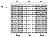
FIG. 4A is a top view of a pocketed spring assembly.
Fig. 4B is a top view of another pocket spring assembly.
Fig. 5A is a top view of a post-processed pocketed spring assembly.
Fig. 5B is a top view of another post-processed pocketed spring assembly.
Fig. 5C is a top view of another pocket spring assembly.
Fig. 5D is a top view of another post-processed pocketed spring assembly.
Figure 6 is a side view of an apparatus for carrying out one of the methods for making one of the fabrics of the present invention.
Fig. 7 is an enlarged view of encircled region 7 of fig. 6.
Fig. 8 is a side view of another apparatus for carrying out one of the methods for making one of the fabrics of the present invention.
Figure 9 is a side view of an apparatus for practicing one of the methods for making one of the fabrics of the present invention.
Fig. 10 is a perspective view of a portion of an ultrasonic laminator laminating three material web materials into a unitary three-layer fabric.
Fig. 11 is an enlarged view of encircled area 11 of fig. 10.
FIG. 12A is a partial end view of one of the spring strings of the pocketed spring assembly of FIG. 1 in an ambient condition.
Fig. 12B is a partial end view of the spring string of fig. 12A compressed.
Fig. 12C is a partial end view of the spring string of fig. 12A further compressed.
Fig. 13 is a perspective view, partially in section, of a portion of another embodiment of a spring string in an unloaded state.
FIG. 14 is a side view of an apparatus for practicing one of the methods of making a fabric of the present invention.
Fig. 15 is an enlarged view of the circled area 15 of fig. 14.
FIG. 16 is a side view of an apparatus for practicing one of the methods of making a fabric of the present invention.
Figure 17 is a perspective view of a portion of an ultrasonic laminator laminating four webs of material into a unitary four-layer fabric.
Fig. 18 is an enlarged view of the encircled area 18 of fig. 17.
Detailed Description
Referring initially to fig. 1, there is shown a bedding article in the form of a one-sided mattress 10 incorporating the principles of the present invention. The article or mattress 10 includes a pocketed spring assembly 12, on top of which is placed a conventional padding or cushioning layer 14,16, the padding or cushioning layer 14,16 may be foam, fabric, gel, pocketed spring blanket, one or more pieces of scrim or any other suitable material or any combination thereof. The pocketed spring assembly 12 may be surrounded by a border 17 (only a portion of which is shown in fig. 1) made of foam or any other suitable material. Although fig. 1, 1A, 1B, and 1C illustrate one type of bezel 17, the bezel may take other forms or shapes of any desired size, such as pocketed coil springs. Instead of a foam border, it has become common to at least partially surround a pocketed spring assembly with springs having a different diameter and height than the pocketed springs inside the pocketed spring assembly. In any of the products shown or described herein incorporating any of the embodiments of pocketed spring assemblies shown or described herein, the border may be omitted.
The pocketed spring assembly 12 is located on a base 18, all of which are encapsulated in a cushioned coating material 20. The base 18 and rim 17 are known in the industry as "buckets" into which the pocketed spring assemblies 12 are inserted before the "buckets" are coated with one or more cushions or cushioning. The base 18 may be foam, a scrim sheet, a plastic sheet, wood, or any other known material.
As shown in FIG. 1, when fully assembled, the article 10 has a length "L" (only one shown in FIG. 1) defined as the linear distance between the opposing end surfaces 22. Similarly, the assembled article 10 has a width "W" (only one shown in FIG. 1) defined as the linear distance between the opposing side surfaces 24. In the article shown in FIG. 1, the length is shown to be greater than the width. However, it is within the scope of the invention that the length and width may be the same as in a square article.
As shown in FIGS. 1 and 2, the pocketed spring assembly 12 is made of a plurality of strings 26 of pocketed springs 28 joined together. In the pocketed spring assembly 12 shown in fig. 1, each string 26 of pocketed springs 28 extends longitudinally or top-to-bottom along the entire length of the pocketed spring assembly 12. Although the strings 26 of pocketed springs 28 are shown as extending longitudinally or top-to-bottom in the pocketed spring assemblies 12 of FIG. 1, they may extend laterally or side-to-side, as shown in the pocketed spring assemblies 12a shown in the articles 10a, 10C of FIGS. 1A and 1C, respectively. The pocketed spring assembly 12a includes a plurality of strings 26a of pocketed springs 28, which are identical to the spring strings 26, but are shorter in length. In any of the embodiments shown or described herein, the strings may extend longitudinally (from end to end) or transversely (from side to side).
Fig. 1B shows a one-sided mattress 10B, which one-sided mattress 10B includes pocketed spring assemblies 12 and borders 17 identical to those shown in the mattress 10 of fig. 1. However, the mattress 10B of FIG. 1B has a pocketed top 30 in addition to the cushion layer 14, the cushion layer 14 being located above and below the pocketed top 30, the pocketed top 30 employing individually pocketed miniature or miniature coil springs. Although one configuration of a bagged top 30 is shown, any bagged top known in the art may be used, such as those disclosed in U.S. patent nos. 9,943,173 and 9,968,202, each of which is incorporated herein by reference in its entirety.
Fig. 1C shows a two-sided mattress 10C that includes pocketed spring assemblies 12a and a border 17. In addition to the cushion layer 14, the mattress 10c of fig. 1B also has a pocketed top 30 above and below the pocketed spring assemblies 12a, with the cushion layer 14 above and below each pocketed top 30. Although the mattresses 10, 10a, 10B shown in fig. 1, 1A, and 1B, respectively, are single-sided mattresses, any of the pocketed spring assemblies shown or described herein may be incorporated into any bedding or seating product shown or described herein, including double-sided mattresses or seat cushions, such as the mattress 10C shown in fig. 1C. If desired, any padding or cushioning layer, including one or more of the bagged tops 30, may be omitted in any of the embodiments shown or described herein.
The strings of pocketed springs 26, 26a and any other strings of springs described or illustrated herein may be connected in a parallel relationship, for example, by gluing the sides of the strings together in an assembly machine, thereby producing a spring assembly or spring matrix having rows and columns of pocketed springs that are joined together by gluing, welding, or any other conventional assembly process commonly used to produce pocketed spring cores or assemblies.
Referring to fig. 4A, the longitudinally extending strings 26 of pocketed spring assemblies 12, along with any other strings described or illustrated herein (including the transversely extending strings 26a of pocketed spring assemblies 12 a), may be joined such that the individual pocketed springs 28 are aligned in transversely extending rows 32 (extending from side to side) and longitudinally extending columns 34 (extending from top to bottom).
Alternatively, as shown in fig. 4B, the longitudinally extending springs 26 of the pocketed spring assemblies 12B, along with any other strings described or illustrated herein (including the transversely extending strings 26a of pocketed spring assemblies 12 a), may be offset from one another. In this arrangement, as shown in FIG. 4B, the individual pocketed springs 28 are not aligned in rows and columns; instead, the individual pocketed springs 28 fill the voids 36 of adjacent strings. Any arrangement of strings may be incorporated into any pocketed spring assembly or core shown or described herein.
Fig. 2A shows a partial side view of an end of one of the strings 26 of pocketed springs 28 of the pocketed spring assembly 12 being compressed or under an external load. Fig. 2B shows a partial side view of a portion of the string 26 of pocketed springs 28 of fig. 2A being decompressed or moved toward a relaxed state upon removal of an external load. FIG. 3 is a perspective view of a portion of the string 26 of pocketed springs 28 of FIG. 2A in a relaxed state without an external load.
As best shown in fig. 2A, 2B and 3, each string 26 of pocketed springs 28 includes a row of interconnected fabric pockets 38. Each of the fabric bags 38 contains at least one resilient member, such as a coil spring 40. The elastic member need not be a coil spring; it may be made of foam or other resilient material. The coil spring 40 is preferably made from a single wire of uniform diameter, but may be made from other materials, stranded wire and/or may have a non-uniform diameter, such as a barrel spring.
As best shown in fig. 3, each coil spring 40 has a central or longitudinal axis a, an upper end turn 42, a lower end turn 44, and a plurality of central convolutions 46 between the end turns. Fig. 2A, 2B and 3 illustrate a coil spring 40 in which the end turns 42, 44 have a diameter generally the same as the diameter of the central convolution 46. However, any known coil spring may be used within any fabric pouch 38. Not all of the coil springs within a pocketed spring assembly need be identical, although they are in most cases identical. The pocketed spring assembly of the present invention may use foam blocks or other resilient members instead of coil springs. One or more pockets may have more than one spring, such as a coil spring, wherein at least a cushion, such as foam, is inserted inside, above or below the coil spring, or any combination thereof.
Preferably, a fabric is used to form the pocketed spring string 26. As described herein, because at least one of the several layers of fabric does not permeate the airflow through the fabric, the fabric does not permeate the airflow through the fabric itself. Air moves between adjacent fabric bags 38 and into and out of the cluster 26 only through gaps or valves along the seams or portions of the seams.
The fabric is folded onto itself around a plurality of coil springs 40. As best shown in fig. 3, the opposite sides or plies 48,50 of the fabric are welded or otherwise secured together in sections to form a longitudinally sectioned seam 52 and a plurality of separate or transversely sectioned seams 54. Fig. 3 shows the lamina 48 closest to the reader and the lamina 50 behind the coil spring 40.
As best shown in fig. 3, the opposite edges 56 of the fabric used to form the pocketed spring strings 26 are aligned and spaced a distance (indicated by reference numeral 58) from the longitudinal side seams 52. Although the figures indicate that the longitudinal seam 52 is below the free edge 56 of the fabric, the longitudinal seam 52 may be above the free edge 56 of the fabric. This is known in the industry as the side seam of the spring string.
As shown in FIG. 3, in the unloaded condition, the string 26 of pocketed springs has a generally flat top surface 60 in a top plane P1 and a parallel generally flat bottom surface 62 in a bottom plane P2. The linear distance between the top and bottom surfaces of the string of pocketed springs 26 defines the height H of the string of pocketed springs 26. This linear distance further defines the height H of the pocketed spring assembly 12, as each of the spring strings 26 has the same height. However, variations in the height of the spring strings are also within the contemplation of the present invention.
As best shown in fig. 2A, 2B and 3, the longitudinal seam 52 includes a plurality of spaced apart linear weld segments 64 formed using an ultrasonic welding horn and anvil (not shown) as disclosed in U.S. patent application No.15/062,318. Gaps or valves 66 are located between adjacent linear weld segments 64 to allow air to flow between the weld segments 64 as indicated by arrows 77,79 in fig. 2A and 2B, respectively.
At least some of the longitudinal seams 52 of the string may not be segmented or may be only partially segmented, depending on the desired airflow into and out of the fabric pockets 38 of the string 26 or 26 a. For example, the longitudinal seam 52 of the spring string may not be segmented at all, so long as the transverse or separation seam 54 is at least partially segmented to allow airflow into and out of the fabric pocket.
As best shown in fig. 2A, 2B and 3, each transverse or separation seam 54 includes a plurality of spaced apart linear weld segments 68 formed using an ultrasonic welding horn and anvil (not shown) as disclosed in U.S. patent application serial No.15/062,318 to join the opposed plies 48,50 of fabric. Gaps or valves 70 are located between adjacent linear weld segments 68 to allow air to flow between the weld segments 68.
Depending on the desired airflow into and out of the fabric pockets 38 of the cluster 26, 26a, at least some of the transverse or separation seams 54 of the cluster may not be segmented or may be only partially segmented, so long as the longitudinal seams 54 are at least partially segmented to allow airflow into and out of the fabric pockets.
As shown in FIG. 2A, when a load is applied to the pocketed springs 28 of the string 26, as indicated by arrows 72, air exits the pockets 38 through gaps 70 between adjacent welded segments 68 of the transverse or separation seam 54 because the multi-layer fabric is impervious to air flow. See the airflow indicated by arrow 75. Air exits the string 26 through the gaps 70 between adjacent fabric pockets 38 and through the outermost or end of the spring string 26 or the gap 70 separating the seams 54.
In addition, air may exit the fabric bag 38 through gaps 66 between the welded segments 64 of the longitudinal seams 52. See the airflow indicated by arrow 77. As shown in fig. 2A, the size of the gaps 70 between the welded segments 68 of the transverse or separation seam 54, along with the size of the gaps 66 between the welded segments 64 of the longitudinal seam 52 of the bag 38, define how quickly air can exit from the bag 38. Since the fabric is impermeable to air flow, air cannot exit the bag 38 except through the gaps. Different spring strings may have different performance characteristics based on the size of the gap 70 in the transverse or separation seam 54 and/or the gap 66 in the longitudinal seam 52, or any combination thereof. Depending on the air flow, a spring string made of such an air-impermeable fabric may impart different stiffness characteristics when a user or person applies a load on the spring string.
As shown in fig. 2B, when the load is removed from the fabric bag 38, the coil spring 40 lifts the fabric bag 38 upward in the direction of arrow 74. Since the fabric is impermeable to air flow, air enters the bag 38 through the gaps 70 between the welded sections 68 of the transverse or separation seams 54. See the airflow indicated by arrow 81. Air enters the rope 26 between the fabric pockets 38 through these gaps 70 and through the outermost or end transverse or gap 70 separating the seams 54.
Additionally, air may enter the fabric pocket 38 through gaps 66 between the welded segments 64 of the longitudinal seam 52. See the airflow indicated by arrow 79. As shown in fig. 2B, the size of the gaps 70 between the welded segments 68 of the transverse or separation seam 54, along with the size of the gaps 66 between the welded segments 64 of the longitudinal seam 52 of the bag 38, define how quickly air can enter the bag 38. Since the fabric is impermeable to air flow, air does not enter the bag 38 unless it passes through the gaps.
Although the welded segments in the illustrated embodiment are shown as heat welded spaced apart rectangular segments, any of the sections of the seam may be other shapes, such as spaced dots of any desired size, oval, or triangular.
As shown in fig. 3, the fabric material of each of the strings 26 does not permeate the airflow through the fabric. The fabric includes three layers, as shown in fig. 3, from the inside of the fabric pocket 38 outward: 1) a fabric protective layer 76; 2) an air barrier layer 78; and 3) a sound attenuating or silencing layer 80. More specifically, the fabric protection layer 76 may be a polypropylene nonwoven fabric layer having a density of about 1 ounce per square yard available from Atex registered with guerbell, georgia. Air barrier 78 may be a polyether thermoplastic polyurethane film layer having a thickness of about 1.0mil (0.001 inches) available from American Polyfilm, registered by Branford, Connecticut. The sound attenuation layer may be a layer of lofty needled polyester batting having a density of 0.5 ounces per square foot available from Milliken & Company, registered with St.Patanburg, south Carolina.
These materials and material specifications (e.g., density provided for the outer layer) have proven effective but are not intended to be limiting. For example, the thickness of the impermeable intermediate layer of the thermoplastic polyurethane film may vary depending on the desired characteristics of the multilayer fabric. The recited thickness of 1.0mil is not intended to be limiting. The sound attenuation layer need not be made of polyester; it may be made of other materials. Similarly, the fibrous batting does not require lofting.
The intermediate thermoplastic polyurethane film layer 78 is impermeable to air flow. The lofty needled polyester batting layer 80 acts as an acoustic damping layer that mutes and muffles the membrane layer 78 when the spring is released from load (pressure in the bag going from positive to negative) or when the spring is loaded (pressure in the bag going from neutral to positive). The polypropylene nonwoven fabric layer 76 keeps the segmented air passages open so that the bag 38 can "breathe". Without the polypropylene nonwoven fabric layer 76 closest to the spring 40, the intermediate thermoplastic polyurethane film 78 would cling to itself and not allow sufficient air to pass through the segmented air passages, valves or gaps in the seam. The polypropylene nonwoven fabric protective layer 76 closest to the spring also makes the use more durable by protecting the airtight intermediate thermoplastic polyurethane film layer 78 from contact with the spring 40 and from degradation from wear against the spring 40.
Although fig. 3 shows a portion of a spring string 26 used in a pocketed spring assembly 12, a triple layer of fabric impermeable to air flow may be used in any of the spring strings shown or described herein, such as the spring string 26a used in a pocketed spring assembly 12 a.
Fig. 5A shows a post-processed pocketed spring assembly 12d having different regions or sections of different stiffness. The pocketed spring assembly 12d includes a plurality of longitudinally extending strings of springs 26d, 26dd joined together in an arrangement for bedding or seating products such as mattresses. It can be seen that the longitudinally extending spring strings 26d, 26dd are disposed in two regions or sections within the pocketed spring assembly 12 d. By way of example, two regions 82,84 are shown, wherein the two regions generally correspond to a "hard" region or section 82 and a "soft" region or section 84. The longitudinally extending strings of springs 26d of the "stiff" regions 82 are each strings of springs constructed of multiple layers of impermeable fabric as shown and described herein. The longitudinally extending spring strings 26dd of the "soft" region 84 are spring strings each constructed of a conventional single layer nonwoven polypropylene fabric permeable to airflow through the fabric.
Referring now to fig. 5B, the laterally extending strings of springs 26e, 26ee are shown as one preferred arrangement of pocketed spring assemblies 12e for bedding or seating products, such as mattresses. It can be seen that the laterally extending spring strings are disposed in a plurality of regions within the pocketed spring assembly 12 e. As an example, three regions are shown, which correspond approximately to the position of the sleeper's head and shoulders, middle portion, knees and feet. As another example, the two end "soft" regions 86 each comprise a spring string 26ee formed of a conventional single layer nonwoven polypropylene fabric permeable to air flow through the fabric. The transversely extending spring strings 26e of the intermediate or "stiff" regions 88 are each a string of springs constructed of multiple layers of impermeable fabric as shown and described herein.
Fig. 5C shows another embodiment of a pocketed spring assembly incorporating spring strings made of different fabrics. Fig. 5C shows longitudinally extending strings of springs 26f, 26ff disposed in a pocketed spring assembly 12f for bedding or seating products, such as mattresses. It can be seen that the longitudinally extending spring strings 26f, 26ff are arranged in an alternating manner in the pocketed spring assembly 12 f. As shown in FIG. 5C, each longitudinally extending string 26f of pocketed spring assemblies 12f is shaded to show that the string is constructed of multiple layers of impermeable fabric as shown and described herein. Each of the other longitudinally extending spring strings 26ff of the spring assembly are not shaded, thereby illustrating that the spring strings are constructed of a conventional single layer of non-woven polypropylene fabric that is permeable to air flow through the fabric.
Fig. 5D shows another embodiment of a pocketed spring assembly 12g incorporating a spring string made of a different fabric. Fig. 5D shows longitudinally extending spring strings 26g, 26gg disposed in a pocketed spring assembly to provide edge support. As shown in FIG. 5D, the longitudinally extending spring string 26g inside the spring assembly is shaded to show that the spring string is constructed of multiple layers of impermeable fabric as shown and described herein. The two outermost longitudinally extending spring strings 26gg of the pocketed spring assembly along each side of the pocketed spring assembly 12g are not shaded, showing that each of these spring strings is constructed of a conventional single layer of non-woven polypropylene fabric that is permeable to air flow through the fabric. Of course, the opposite is true. One or both spring strings extending along the sides of the pocketed spring assembly may be made using a multi-layer impermeable fabric, and the inner spring string may be made using a conventional single layer nonwoven polypropylene fabric that permeates air flow through the fabric.
Fig. 6 shows an apparatus 90 for performing the method of making a fabric for use in the spring strings shown and described herein or for use in any other bedding or seating product, including the product described in U.S. patent No.9,968,202.
Referring to fig. 6, the method includes: a source 92 of a first protective layer of polypropylene nonwoven is provided which may be a roll of polypropylene nonwoven or any other source. The protective polypropylene nonwoven web 76 from source 92 passes around a roller 94 and into a laminator 96. The method also includes providing a source 98 of thermoplastic polyurethane film intermediate air barrier, which may be a roll of film or any other source. The web 78 of airtight thermoplastic polyurethane film from the source 98 passes around a roller 100 and into the laminator 96. The method further includes providing a source 102 of a third sound attenuating layer of lofty needled polyester batting, which may be a roll of batting or any other source. A web of sound attenuating material, such as a lofty needled polyester fiber batt 80 from a source 102, passes around a roller 104 and into the laminator 96. The method further includes providing a source of gum 106, which may be a roll of gum available from Hanes Industries of conopover, north carolina. A web of glue 108 from a source 106 passes around a roller 110 and into the laminator 96. The glue web 108 is located between the web of sound attenuating material 80, such as a lofty needle punched polyester fiber batt, and the web of air barrier material 78, such as a thermoplastic polyurethane film. Once inside the laminator 96, the glue web 108 is heated so that it melts to secure the lofted, needled polyester fiber batt sound-attenuating web 80 and the thermoplastic polyurethane film air-tight web 78 together. The residual heat from the laminator 96 can temporarily secure the polypropylene nonwoven fabric web 76 to the thermoplastic polyurethane film intermediate air impermeable web 78 to produce a three-layer web 112, which three-layer web 112 is passed between press rolls 114 to further secure the three layers together to form a finished fabric 116 shown in detail in fig. 7. As shown in fig. 6, a cutter 118 may be used to cut the finished web 116 to the desired size. Alternatively, the finished fabric 116 may be rolled into a roll 120 after cutting.
Fig. 8 shows the same apparatus used to implement the process shown in fig. 7, but with the addition of another glue source and glue web to further secure the three layers 76,78 and 80 of impermeable fabric 116 shown in fig. 7 together. The method of making the article web 116 also includes providing a second source of glue 124, which may be a roll of glue available from Hanes Industries of Conover, north carolina. A web of glue 126 from a source 124 is passed around a roller 128 and into the laminator 96. The glue web 126 is located between the polypropylene nonwoven protective web 76 and the thermoplastic polyurethane film airtight web 78. Once inside the laminator 96, the glue web 126 is heated so that it melts securing the protective polypropylene nonwoven web 76 and the thermoplastic polyurethane film hermetic web 78 together. The heat from the laminator 96 melts each glue web to form a three-layer web 112, which three-layer web 112 passes between press rolls 114 to further secure the three layers together into a finished fabric 116 shown in detail in fig. 7. As shown in fig. 6, a cutter 118 may be used to cut the finished fabric 116 to the desired size. Alternatively, the finished fabric 116 may be rolled into a roll 120 after cutting.
Figure 9 shows a slightly different apparatus for carrying out a similar process for making the three layers of impermeable fabric 116 shown in figure 7. This method of making the three-layer impermeable fabric web 116 uses a glue sprayer 130 that can apply glue to one surface of the thermoplastic polyurethane film web 78 between the sound attenuating lofted needled polyester fiber batt web 80 and the thermoplastic polyurethane film air-tight web 78 before the thermoplastic polyurethane film web 78 enters the laminator 96. Once inside the laminator 96, the glue may be heated so that it melts to secure the sound attenuating lofted needled polyester fiber batt web 80 and the thermoplastic polyurethane film airtight web 78 together. The heat from the laminator 96 melts the glue to form a three-layer fiber web 112, which three-layer fiber web 112 passes between press rolls 114 to further secure the three layers together to form a finished fabric 116 shown in detail in fig. 7. As shown in fig. 6, a cutter 118 may be used to cut the finished three-layer impermeable web 136 to the desired size. Alternatively, the finished three-layer impermeable web 116 can be wound into a roll 120 after cutting.
Although not shown, a second sprayer may be incorporated into the system or apparatus to apply glue to both sides of the thermoplastic polyurethane film airtight web 78 before the web passes through the laminator 96.
Figures 10 and 11 illustrate different apparatus for carrying out the different methods of making the three layers of impermeable fabric 136 shown in figure 11. This method of making the article three-layer impermeable fabric web 136 uses an ultrasonic laminator that can use ultrasonic welds 134 to weld three incoming webs of material together. As shown in fig. 10, an incoming polypropylene nonwoven protective web 76 is welded to a thermoplastic polyurethane film air-tight web 78 and a lofty needle-punched polyester fiber batt sound-attenuating web 80. The ultrasonic laminator 132 joins the three webs at selected locations 134 to produce a three layer impermeable layer fabric web 136 shown in detail in fig. 11. As shown in fig. 6, a cutter 118 may be used to cut the finished three-layer impermeable web 136 to the desired size. Alternatively, as shown in fig. 6,8 and 9, the finished fabric 136 may be wound into a roll.
Fig. 12A, 12B and 12C illustrate another version of a string 26' that may be used in any of the pocketed spring assemblies shown or described herein and incorporated into any desired product. The string 26' may be made of any of the fabrics disclosed or illustrated herein. The string 26' functions in the same manner as the strings 26, 26a shown and described herein. However, the longitudinal section seam 52 'and the separating or transverse section seam 54' are shaped differently. As in the fabric pockets 38 of the cluster 26, 26a described and illustrated herein, each fabric pocket 38 ' of the cluster 26 ' has at least one coil spring 40 within the fabric pocket 38 '.
As shown in fig. 12A, 12B and 12C, the longitudinal seam 52 'of the string 26' includes a plurality of spaced apart linear weld segments 64 ', the plurality of spaced apart linear weld segments 64' being formed using an ultrasonic welding horn and anvil (not shown) as disclosed in U.S. patent No.9,968,202. Gaps 66 ' are located between adjacent linear weld segments 64 ' to allow air to flow through the gaps 66 ' between the weld segments 64 ', as shown by arrows 77 ' in fig. 12B and 12C. Air may flow out of the string 26 ' through the gaps 66 ' between the welded segments 64 ' of the longitudinal joint 52 ' at different rates depending on the load placed on the string 26 '. Similarly, air may flow into the string 26 ' through the gaps 66 ' between the welded segments 64 ' of the longitudinal seam 52 ' at different rates depending on the load being removed from the string 26 '. For the purposes of this document, the gap 66 ' between the welded segments 64 ' of the longitudinal seam 52 ' of the string 26 ' may be considered a valve sized to vary in size depending on the load applied to or removed from the string 26 ' to control the air flow as described below.
As shown in fig. 12A, 12B and 12C, each transverse seam 54 ' (only one shown) of the string 26 ' includes a plurality of spaced apart linear weld segments 68 ' formed using an ultrasonic welding horn and anvil (not shown) as disclosed in U.S. patent No.9,968,202 to join the opposing plies 48 ', 50 ' of fabric. Gaps or valves 70 ' are located between adjacent linear weld segments 68 ' to allow air to flow between the weld segments 68 '. Air may flow from one pocket 38 'to an adjacent pocket 38' through the gaps 70 'of the transverse seams 54' of the string 26 'between the welds 68'. As shown by arrows 79 ' in fig. 12B, air can flow into and out of the rope 26 ' through the gaps 70 ' of the outermost transverse seams 54 ' at the opposite ends of the rope 26 '. For purposes of this document, the gaps 70 'of the transverse seams 54' of the string 26 'may be considered valves that vary in size depending on the load applied to or removed from the string 26' to control the air flow as described below. The gaps 70 'of the transverse seams 54' and the gaps 66 'of the longitudinal seams 52' of the string 26 'act as valves to control the flow of air into and out of the pockets 38' of the string 26 'without any other material or equipment other than the multi-ply fabric of the string 26'. The construction of the rope 26 'has inherent valves in the rope 26' between the seam sections that control the flow of air into and out of the pockets 38 'of the rope 26' depending on, among other factors, the size of the seam sections, the load placed on the rope 26 ', and the composition of the fabric material of the rope 26'.
Fig. 12A shows a string 26 'without any load on the string 26'. The string 26' is in a relaxed state. Air does not flow through the gaps 70 ' of the transverse seams 54 ' or the gaps 66 ' of the longitudinal seams 52 ' of the string 26 '. The air pressure within the bag 38 ' is at atmospheric pressure at ambient temperature and therefore the valves 66 ', 70 ' are in a relatively restricted state, i.e., relatively flat. The opposing fabric plies 48 ', 50 ' of the transverse seam 54 ' may be in contact with each other or in close proximity to each other. See fig. 12A.
Fig. 12B shows a string 26 'with a light load placed on the string 26', as indicated by arrow 122. Once a light load is placed on the string 26 ', at least some of the valves or gaps 66 ' of the longitudinal seams 52 ' and/or at least some of the valves or gaps 70 ' of the transverse seams 54 ' of the string 26 ' or any combination thereof are slightly opened so that air flows through at least some of the gaps 70 ' of the transverse seams 54 ' of the string 26 ' and/or through at least some of the gaps 66 ' of the longitudinal seams 52 ' or any combination thereof.
Fig. 12C shows a string 26 'placing a greater load on the string 26', as indicated by three arrows 123. Once a large load is placed on the string 26 ', at least some of the valves or gaps 66 ' of the longitudinal seams 52 ' and/or at least some of the valves or gaps 70 ' of the transverse seams 54 ' of the string 26 ' or any combination thereof are opened larger such that air flows through at least some of the gaps 70 ' of the transverse seams 54 ' of the string 26 ' and/or through at least some of the gaps 66 ' of the longitudinal seams 52 ' or any combination thereof.
If a load significantly greater than that required to open the valves 70 'of the transverse seams 54' and the valves 66 'of the longitudinal seams 52' is applied to the rope 26 ', the fabric material of the rope 26' will stretch elastically and open further to allow more air to pass through the valves or gaps in the seams. Thus, the valve reacts to the specific load applied. This reaction contributes to the unique luxury feel of the pocketed spring assembly made from strings made according to the present invention. The ability of the valve to stretch and react to air pressure is largely due to the intermediate thermoplastic polyurethane film layer. The intermediate thermoplastic polyurethane film layer is a relatively elastic material that returns to its original shape after the load is removed. When the load is released, the valve returns to its original state, which is a relatively restricted state in which the air pressure within the bag is at atmospheric pressure at ambient temperature.
It is also within the contemplation of the invention to manufacture only some of the strings of pocketed spring assemblies according to the invention. For example, every other string may be made of conventional fabric.
Further, it is within the contemplation of the invention that the different strings shown and described herein may be used together. For example, every other string may have a segmented seam as shown in fig. 12A, 12B and 12C and every other string may have a segmented seam as shown and described elsewhere in this document.
Fig. 13 shows a view similar to fig. 3, but showing a different string 26b having a different web material than the string 26 described herein. For simplicity, like components are denoted by like reference numerals. The string 26b may be used in any of the embodiments shown or described herein. The four layers of fabric material of the rope 26b do not penetrate the air flow through the fabric, as does the three layers of fabric material of the rope 26. The fabric includes four layers, as shown in fig. 13, from the inside of the fabric pocket 38 outward: 1) a fabric inner protective layer 76; 2) an air barrier layer 78; 3) a sound attenuating or silencing layer 80; and 4) a fabric outer protective layer 76.
The thermoplastic polyurethane film layer 78 is impermeable to air flow. The layer of pinking needle polyester batting 80 acts as an acoustic dampening layer that mutes and muffles the membrane layer 78 when the spring is released from the load (pressure in the bag going from positive to negative) or is loaded (pressure in the bag going from neutral to positive). The polypropylene nonwoven fabric layer 76 keeps the segmented air passages open so that the bag 38 can "breathe". Without the polypropylene nonwoven fabric layer 76 closest to the spring 40, the thermoplastic polyurethane film 78 would stick to itself and not allow sufficient air to pass through the segmented air passages, valves or gaps in the seam. The polypropylene nonwoven fabric protective layer 76 closest to the spring also makes the product more durable by protecting the airtight thermoplastic polyurethane film layer 78 from contacting the spring 40 and from deterioration due to abrasion against the spring 40. The polypropylene nonwoven fabric protective layer 76 furthest from the springs protects the pinus needle punched polyester fiber cotton batt layer 80.
Although fig. 13 shows a portion of a string of springs 26b, four layers of fabric impermeable to air flow may be used in any of the spring strings shown or described herein, such as the string 26a for the pocketed spring assemblies 12a or the string 26 for the pocketed spring assemblies 12.
Fig. 14 shows an apparatus 90b for performing a method of manufacturing a web for a spring string as shown and described herein or for any other bedding or seating product, including the product described in U.S. patent No.9,968,202.
Referring to fig. 14, the method includes providing a source 92 of a first protective layer of polypropylene nonwoven, which may be a roll of polypropylene nonwoven or any other source. The protective polypropylene nonwoven web 76 from source 92 passes around a roller 94 and into a laminator 96. The method further includes providing a source 98 of thermoplastic polyurethane film intermediate air barrier, which may be a roll of film or any other source. The web 78 of airtight thermoplastic polyurethane film from the source 98 passes around a roller 100 and into the laminator 96. The method further includes providing a source 102 of a third acoustic attenuation layer of lofty needled polyester batting, which may be a roll of batting or any other source. A web of sound attenuating material 80, such as a lofty needled polyester batting, from a source 102 passes around a roller 104 and into the laminator 96. The method further includes providing a source 95 of a second protective layer of polypropylene nonwoven, which may be a roll of polypropylene nonwoven or any other source. The protective polypropylene nonwoven web 76 from source 95 passes around roller 97 and into laminator 96.
The method further includes providing a source of gum 106, which may be a roll of gum, which may be commercially available from Hanes Industries of connoft, north carolina. A web of glue 108 from a source 106 passes around a roller 110 and into the laminator 96. The glue web 108 is located between the web of sound attenuating material 80, such as pine needle punched polyester batting, and the web of air barrier material 78, such as a thermoplastic polyurethane film. Once in the laminator 96, the glue web 108 is heated to melt it to secure the lofted needled polyester fiber batt sound attenuating web 80 and the thermoplastic polyurethane film air tight web 78 together. The residual heat from the laminator 96 can temporarily secure the polypropylene nonwoven fabric web 76 to the thermoplastic polyurethane film intermediate air tight web 78 to form a four layer web 112b that is passed between press rollers 114 to further secure the four layers together to form the finished fabric 116b shown in detail in fig. 15. As shown in fig. 14, a cutter 118 may be used to cut the four layers of finished fabric 116b to a desired size. Alternatively, four layers of the finished fabric 116b may be wound into a roll 120b after cutting.
Figure 16 shows a slightly different apparatus for practicing a similar method of making the four layers of impermeable fabric 116b shown in figure 15. The method of making the finished four-layer impermeable fabric web 116b uses a glue shower 130, which glue shower 130 can apply glue to one surface of the thermoplastic polyurethane film web 78 between the lofty needle-punched polyester fiber batt web 80 and the thermoplastic polyurethane film air-tight web 78 before the thermoplastic polyurethane film web 78 enters the laminator 96. Once in the laminator 96, the glue may be heated to melt it to secure the sound attenuating lofted needled polyester fiber batt web 80 and the thermoplastic polyurethane film airtight web 78 together. The heat from laminator 96 melts the glue to form a four-layer web 112b which is passed between press rollers 114 to further secure the four layers together to form a finished fabric 116b as shown in detail in fig. 15. A cutter 118 may be used to cut the finished four layers of impermeable fabric 116b to the desired size. Alternatively, the finished four-ply impermeable fabric 116b may be rolled into a roll 120b after cutting.
Although not shown, a second shower may be incorporated into the system or apparatus to apply glue to both sides of the thermoplastic polyurethane film airtight web 78 before the web passes through the laminator 96.
Figures 17 and 18 illustrate different apparatus for practicing the different manufacturing methods for making the four layers of impermeable fabric 136b shown in figure 18. The method of making the finished four-layer impermeable web of fabric 136b uses an ultrasonic laminator 132 which can use ultrasonic welds 134 to weld four incoming webs of material together. As shown in fig. 17, one of the incoming polypropylene nonwoven protective webs 76 is welded to a thermoplastic polyurethane film air-tight web 78, while the other incoming polypropylene nonwoven protective web 76 is welded to a bulky needle punched polyester fiber batt sound attenuating web 80. The ultrasonic laminator 132 joins the four webs together at selected locations 134 to form a four-layer impermeable web of fabric 136b as shown in detail in fig. 18. As shown in fig. 14 and 16, a cutter 118 may be used to cut the finished four-layer impermeable web 136b to the desired size. Alternatively, the finished fabric 136b may be rolled into a roll as shown in fig. 14 and 16.
The various embodiments of the invention shown and described are for illustrative purposes only, as the figures and description are not intended to limit or restrict the scope of the claims in any way. Those skilled in the art will appreciate that various changes, modifications and improvements may be made to the invention without departing from the spirit or scope of the invention. The invention in its broader aspects is therefore not limited to the specific details and representative apparatus and method shown and described. Accordingly, departures may be made from such details without departing from the spirit or scope of the general inventive concept. The invention resides in each individual feature described herein independently, and each and every combination of any and all those features. Accordingly, the scope of the invention is to be limited only by the following claims and equivalents thereof.
Claims (21)
1. A bedding or seating product comprising:
a pocketed spring assembly comprising a plurality of parallel strings of springs joined together, each of the strings of springs comprising a plurality of individual pocketed springs, each of the strings of springs comprising fabric joined along longitudinal segmented seams, first and second opposing plies of fabric being on opposite sides of the spring, a plurality of pockets formed along a length of the string of springs by transverse segmented seams joining the first and second plies, at least one spring being positioned in each of the pockets, wherein the fabric comprises a plurality of layers including a sound attenuation layer between layers of non-woven polypropylene, each of the segmented seams having a gap between segments of the seam such that the size of the gap increases when under load, allowing more air within the pocket to exit the pocket;
a buffer material; and
a cushion cover surrounding said pocketed spring assembly and said cushioning material.
2. A pocketed spring assembly for use in bedding or seating products, the pocketed spring assembly comprising:
a plurality of parallel strings of springs joined together, each of the strings of springs comprising a plurality of individually pocketed springs, each of the strings of springs comprising fabric joined along longitudinal segmented seams, first and second opposing plies of fabric being on opposite sides of the springs, a plurality of pockets formed along a length of the string of springs by transverse segmented seams joining the first and second plies, at least one spring being positioned in each of the pockets, wherein the fabric comprises a plurality of layers including a sound attenuation layer between layers of non-woven polypropylene, each of the segmented seams having gaps between segments of the seams such that the gaps increase in size when loaded, allowing more air within the pocket to exit the pocket.
3. The pocketed spring assembly of claim 2, wherein the fabric further comprises an air impermeable layer.
4. The pocketed spring assembly of claim 3, wherein the fabric comprises four layers.
5. The pocketed spring assembly of claim 4, wherein at least one of the layers is impermeable to air flow.
6. The pocketed spring assembly of claim 2, wherein only one of the layers is impermeable to air flow.
7. The pocketed spring assembly of claim 2, wherein the non-woven polypropylene layer is an outer protective layer on an opposite side of the fabric.
8. The pocketed spring assembly of claim 2, wherein the sound attenuating layer comprises needle punched polyester fiber batting.
9. A fabric for a pocketed spring assembly, the fabric comprising:
a first protective material layer;
a second air impermeable thermoplastic polyurethane film layer;
a third layer of sound attenuating material comprising a needled polyester batting secured to the second layer to prevent noise when the pocketed spring assembly is compressed and expanded, wherein the fabric is oriented such that the first layer of protective material is closest to the springs surrounded by the fabric;
a fourth layer of protective material.
10. The fabric of claim 9, wherein the second and third layers are glued together.
11. The fabric of claim 9, wherein the fabric forms a pocket of the pocketed spring assembly, the pocket surrounding a spring within the pocket, the first layer being closest to the spring.
12. The fabric of claim 11, wherein the second layer is sandwiched between the first layer and the third layer.
13. The fabric of claim 9, wherein the four layers are laminated together.
14. The fabric of claim 9, wherein the fabric forms a plurality of pockets for a spring string of the pocketed spring assembly, each pocket surrounding at least one spring within the pocket.
15. A method of making a fabric for a pocketed spring assembly, the method comprising:
forming a stack comprising a layer of an opposing protective material, an air-impermeable intermediate layer, a sound attenuating layer, and a layer of glue between the air-impermeable intermediate layer and the sound attenuating layer;
passing the stack through a laminator to form a finished fabric; and
and rolling up the finished fabric.
16. The method of claim 15, wherein the glue layer is melted in the laminator.
17. The method of claim 15, wherein the sound attenuation layer is secured to the intermediate layer by the glue to form a sound damping layer in the finished fabric.
18. A method of manufacturing a pocketed spring assembly for use in bedding or seating products, the method comprising:
combining a plurality of parallel strings of springs together, each of said strings comprising a plurality of individually pocketed springs, each of said strings comprising fabric joined along longitudinal seams, first and second opposing plies of fabric being located on opposite sides of said springs, a plurality of pockets formed along the length of said string by transverse segmented seams joining said first and second plies, at least one spring being located in each of said pockets, wherein said fabric is impermeable to air flow and comprises outer layers of polypropylene nonwoven material and an acoustic attenuation layer located between said outer layers, but air within said pockets exits and enters said pockets through gaps between segments of said seams.
19. The method of claim 18, wherein the fabric further comprises a gas impermeable thermoplastic polyurethane film layer.
20. A method of manufacturing a pocket spring assembly, the method comprising:
bringing together a plurality of parallel strings of springs, each of said strings of springs comprising a plurality of individually pocketed springs, each of said strings of springs comprising fabric joined along longitudinal seams, first and second opposing plies of fabric being located on opposite sides of said springs, a plurality of pockets formed along the length of said string of springs by transverse segmented seams joining said first and second plies, at least one spring being located in each of said pockets, wherein said fabric comprises an air impermeable flow layer located between two protective layers such that said fabric allows air to exit and enter said pockets only through gaps between segments of said seams, and said fabric comprises a layer of cellucotton batting for sound attenuation located between two protective layers.
21. The method of claim 20, wherein the protective layers are made of the same material.
Applications Claiming Priority (3)
| Application Number | Priority Date | Filing Date | Title |
|---|---|---|---|
| US16/021,919 | 2018-06-28 | ||
| US16/021,919 US10172472B2 (en) | 2016-03-07 | 2018-06-28 | Pocketed spring assembly having multi-layered impermeable fabric |
| PCT/US2018/064921 WO2020005312A1 (en) | 2018-06-28 | 2018-12-11 | Pocketed spring assembly having multi-layered impermeable fabric |
Publications (1)
| Publication Number | Publication Date |
|---|---|
| CN112512379A true CN112512379A (en) | 2021-03-16 |
Family
ID=68986787
Family Applications (1)
| Application Number | Title | Priority Date | Filing Date |
|---|---|---|---|
| CN201880095142.7A Pending CN112512379A (en) | 2018-06-28 | 2018-12-11 | Pocketed spring assembly with multiple layers of impermeable fabric |
Country Status (5)
| Country | Link |
|---|---|
| EP (1) | EP3813598A4 (en) |
| CN (1) | CN112512379A (en) |
| RU (1) | RU2754414C1 (en) |
| WO (1) | WO2020005312A1 (en) |
| ZA (1) | ZA202007983B (en) |
Citations (10)
| Publication number | Priority date | Publication date | Assignee | Title |
|---|---|---|---|---|
| CN103339669A (en) * | 2011-01-26 | 2013-10-02 | 霓佳斯株式会社 | Sound-proof material and process for production thereof, sound-proof molding, and sound insulation method |
| CN203226520U (en) * | 2013-03-01 | 2013-10-09 | 运时通(中国)家具有限公司 | Bag-in spring structure |
| CN104812273A (en) * | 2012-08-10 | 2015-07-29 | 哈里森斯平克斯部件有限公司 | Resilient unit with different major surfaces |
| CN105658116A (en) * | 2013-06-19 | 2016-06-08 | L&P 产权管理公司 | Pocketed spring assembly comprising strings of springs having Y-shaped seams and inserts |
| US20160213159A1 (en) * | 2014-06-17 | 2016-07-28 | L&P Property Management Company | Pocketed Spring Assembly Comprising Strings of Springs of Different Heights and Enhanced Ventilation |
| CN205601259U (en) * | 2016-05-17 | 2016-09-28 | 绍兴市锋锐机械有限公司 | Compound sack shock mount |
| CN205696796U (en) * | 2016-05-12 | 2016-11-23 | 浙江心梦享家居有限公司 | A kind of bed core combinative structure |
| CN206342225U (en) * | 2016-08-22 | 2017-07-21 | 嘉兴泰恩弹簧有限公司 | A kind of sofa seat bag |
| US20170251820A1 (en) * | 2016-03-07 | 2017-09-07 | L&P Property Management Company | Multi-Layered Impermeable Fabric For Use in Pocketed Spring Assembly |
| CN107427134A (en) * | 2015-03-17 | 2017-12-01 | 理查德·科多斯 | Mattress |
Family Cites Families (6)
| Publication number | Priority date | Publication date | Assignee | Title |
|---|---|---|---|---|
| US3046574A (en) * | 1959-12-23 | 1962-07-31 | Superior Bedding Company | Mattress construction |
| US4234983A (en) * | 1978-10-02 | 1980-11-25 | Simmons Company | Thermally welded spring pockets |
| JP2836877B2 (en) * | 1988-08-05 | 1998-12-14 | スランバーランド・ホールディングス・リミテッド | Spring unit for mattress etc. |
| US6317912B1 (en) * | 2000-03-08 | 2001-11-20 | Kurtis F. Graebe | Bed mattress with air cells and spring pockets |
| RU140068U1 (en) * | 2013-07-26 | 2014-04-27 | Общество с ограниченной ответственностью "АСКОНА-ВЕК" | SPRING BLOCK |
| US10076193B2 (en) * | 2016-03-07 | 2018-09-18 | L&P Property Management Company | Multi-layered impermeable fabric for use in pocketed spring assembly |
-
2018
- 2018-12-11 WO PCT/US2018/064921 patent/WO2020005312A1/en active Application Filing
- 2018-12-11 EP EP18924701.8A patent/EP3813598A4/en active Pending
- 2018-12-11 CN CN201880095142.7A patent/CN112512379A/en active Pending
- 2018-12-11 RU RU2021101573A patent/RU2754414C1/en active
-
2020
- 2020-12-21 ZA ZA2020/07983A patent/ZA202007983B/en unknown
Patent Citations (10)
| Publication number | Priority date | Publication date | Assignee | Title |
|---|---|---|---|---|
| CN103339669A (en) * | 2011-01-26 | 2013-10-02 | 霓佳斯株式会社 | Sound-proof material and process for production thereof, sound-proof molding, and sound insulation method |
| CN104812273A (en) * | 2012-08-10 | 2015-07-29 | 哈里森斯平克斯部件有限公司 | Resilient unit with different major surfaces |
| CN203226520U (en) * | 2013-03-01 | 2013-10-09 | 运时通(中国)家具有限公司 | Bag-in spring structure |
| CN105658116A (en) * | 2013-06-19 | 2016-06-08 | L&P 产权管理公司 | Pocketed spring assembly comprising strings of springs having Y-shaped seams and inserts |
| US20160213159A1 (en) * | 2014-06-17 | 2016-07-28 | L&P Property Management Company | Pocketed Spring Assembly Comprising Strings of Springs of Different Heights and Enhanced Ventilation |
| CN107427134A (en) * | 2015-03-17 | 2017-12-01 | 理查德·科多斯 | Mattress |
| US20170251820A1 (en) * | 2016-03-07 | 2017-09-07 | L&P Property Management Company | Multi-Layered Impermeable Fabric For Use in Pocketed Spring Assembly |
| CN205696796U (en) * | 2016-05-12 | 2016-11-23 | 浙江心梦享家居有限公司 | A kind of bed core combinative structure |
| CN205601259U (en) * | 2016-05-17 | 2016-09-28 | 绍兴市锋锐机械有限公司 | Compound sack shock mount |
| CN206342225U (en) * | 2016-08-22 | 2017-07-21 | 嘉兴泰恩弹簧有限公司 | A kind of sofa seat bag |
Also Published As
| Publication number | Publication date |
|---|---|
| ZA202007983B (en) | 2022-01-26 |
| WO2020005312A1 (en) | 2020-01-02 |
| EP3813598A4 (en) | 2022-03-23 |
| EP3813598A1 (en) | 2021-05-05 |
| RU2754414C1 (en) | 2021-09-02 |
Similar Documents
| Publication | Publication Date | Title |
|---|---|---|
| CA3015228C (en) | Multi-layered impermeable fabric for use in pocketed spring assembly | |
| US10076193B2 (en) | Multi-layered impermeable fabric for use in pocketed spring assembly | |
| US8484784B2 (en) | Slow acting pocketed spring core having fibrous material glued to pockets | |
| US8474078B2 (en) | Slow acting pocketed spring core having cushioning material | |
| US10172472B2 (en) | Pocketed spring assembly having multi-layered impermeable fabric | |
| US10624467B2 (en) | Pocketed spring comfort layer | |
| US10405665B2 (en) | Pocketed spring comfort layer and method of making same | |
| US8266745B2 (en) | Slow acting pocketed spring core having fill material inside pockets | |
| US10667615B2 (en) | Pocketed spring comfort layer and method of making same | |
| US10813462B2 (en) | Pocketed spring comfort layer and method of making same | |
| CA3058187C (en) | Multi-layered impermeable fabric for use in pocketed spring assembly | |
| CN109152487B (en) | Packed type spring comfort liner and preparation method thereof | |
| CN112512379A (en) | Pocketed spring assembly with multiple layers of impermeable fabric |
Legal Events
| Date | Code | Title | Description |
|---|---|---|---|
| PB01 | Publication | ||
| PB01 | Publication | ||
| SE01 | Entry into force of request for substantive examination | ||
| SE01 | Entry into force of request for substantive examination | ||
| RJ01 | Rejection of invention patent application after publication | ||
| RJ01 | Rejection of invention patent application after publication |
Application publication date: 20210316 |