CN112494828A - Medical nursing baking lamp adjusted according to patient action - Google Patents
Medical nursing baking lamp adjusted according to patient action Download PDFInfo
- Publication number
- CN112494828A CN112494828A CN202110044177.1A CN202110044177A CN112494828A CN 112494828 A CN112494828 A CN 112494828A CN 202110044177 A CN202110044177 A CN 202110044177A CN 112494828 A CN112494828 A CN 112494828A
- Authority
- CN
- China
- Prior art keywords
- plate
- cavity
- detection
- gear
- patient
- Prior art date
- Legal status (The legal status is an assumption and is not a legal conclusion. Google has not performed a legal analysis and makes no representation as to the accuracy of the status listed.)
- Granted
Links
Images


Classifications
-
- A—HUMAN NECESSITIES
- A61—MEDICAL OR VETERINARY SCIENCE; HYGIENE
- A61N—ELECTROTHERAPY; MAGNETOTHERAPY; RADIATION THERAPY; ULTRASOUND THERAPY
- A61N5/00—Radiation therapy
- A61N5/06—Radiation therapy using light
- A61N5/0613—Apparatus adapted for a specific treatment
- A61N5/0625—Warming the body, e.g. hyperthermia treatment
-
- A—HUMAN NECESSITIES
- A61—MEDICAL OR VETERINARY SCIENCE; HYGIENE
- A61N—ELECTROTHERAPY; MAGNETOTHERAPY; RADIATION THERAPY; ULTRASOUND THERAPY
- A61N5/00—Radiation therapy
- A61N5/06—Radiation therapy using light
- A61N2005/0626—Monitoring, verifying, controlling systems and methods
-
- A—HUMAN NECESSITIES
- A61—MEDICAL OR VETERINARY SCIENCE; HYGIENE
- A61N—ELECTROTHERAPY; MAGNETOTHERAPY; RADIATION THERAPY; ULTRASOUND THERAPY
- A61N5/00—Radiation therapy
- A61N5/06—Radiation therapy using light
- A61N2005/0635—Radiation therapy using light characterised by the body area to be irradiated
- A61N2005/0642—Irradiating part of the body at a certain distance
Abstract
The invention discloses a medical nursing roast lamp which is adjusted according to the action of a patient, comprising a machine body and a first detection cavity which is symmetrically arranged in the machine body from front to back, wherein a first chute is symmetrically arranged at the upper part and the lower part of the inner wall of the first detection cavity, a first fixed block is arranged on the first chute in a sliding way, a first pressure sensor is arranged on the inner wall of the first detection cavity, a first spring is connected between the first pressure sensor and the first fixed block, and the first pressure sensor can detect the stress so as to judge the position of the patient. Thereby automatically adjusting the position of the baking lamp to be always aligned with the injured part of the patient, thereby enabling the baking lamp to be always used best.
Description
Technical Field
The invention relates to a medical nursing baking lamp adjusted according to the action of a patient, and mainly relates to the technical field of medical baking lamps.
Background
The medical baking lamp is used for clinical physiotherapy and blood circulation promotion, and is very important for warming the affected part after replantation of severed limbs and hand-foot skin flap transplantation due to hand trauma of a patient, so that a 40-60W bulb is usually adopted to irradiate the affected part, the distance between the baking lamp and the irradiated part is 40-60cm, the effect of promoting blood circulation is achieved, medical workers need to measure the distance between the baking lamp and the affected part every time the medical workers use the medical workers, and meanwhile, the patient inevitably moves, so that normal use of the baking lamp is influenced, and the medical baking lamp is improved against the defects.
Disclosure of Invention
The invention aims to solve the technical problem of providing a medical nursing baking lamp which is adjusted according to the action of a patient, and overcomes the problems.
The invention is realized by the following technical scheme.
The invention relates to a medical nursing roast lamp for adjusting according to the action of a patient, which comprises a machine body and first detection cavities symmetrically arranged in the machine body from top to bottom, wherein the inner wall of the first detection cavity is provided with first sliding grooves symmetrically arranged from top to bottom, a first fixed block is arranged on the first sliding grooves in a sliding manner, a first pressure sensor is arranged on the inner wall of the first detection cavity, a first spring is connected between the first pressure sensor and the first fixed block, the first pressure sensor can detect the stress to judge the position of the patient, a first detection block is fixedly arranged between the first fixed blocks, one end of the first detection block extends to the outside, second detection cavities positioned at the lower side of the first detection cavity are symmetrically arranged in the machine body from top to bottom, a second sliding groove is arranged in the second detection cavity, a second detection block is arranged on the second sliding groove in a sliding manner, and the upper end of the second detection block extends to the outside, a second pressure sensor is arranged in the bottom wall of the second detection cavity, a second spring is connected between the second pressure sensor and the second detection block, the second pressure sensor can detect stress to judge whether the patient turns, a baking lamp cavity positioned at the lower side of the second detection cavity is arranged in the machine body, a taking-out port communicated with the outside is arranged on the front wall of the baking lamp cavity, a third chute is arranged on the bottom wall of the baking lamp cavity, a second fixed block is arranged on the third chute in a sliding manner, a placing plate is fixedly arranged at the upper end of the second fixed block, a first electric slide rail is arranged on the placing plate, a base is arranged on the first electric slide rail in a sliding manner, a height plate is arranged in the base, the height plate is connected with the base through an articulated shaft, a first motor is arranged on the right wall of the height plate, and the left end of the first motor is connected with a camshaft, a cam is fixedly arranged on the cam shaft, fourth sliding grooves are symmetrically arranged on the left and right sides in the height plate, a fixed plate is arranged on the fourth sliding grooves in a sliding mode, a third spring is connected between the fixed plate and the front wall of the fourth sliding grooves, the fixed plate is abutted against the cam, a movable plate is fixedly arranged at the rear end of the fixed plate, an adjusting cavity is arranged in the movable plate, a second motor is arranged in the right wall of the adjusting cavity, the left end of the second motor is connected with a gear shaft in a power mode, a first gear is fixedly arranged on the gear shaft, a rotating shaft is rotatably arranged in the movable plate, the right end of the rotating shaft extends into the adjusting cavity and is fixedly provided with a second gear, the second gear is meshed with the first gear, a rotating block is fixedly arranged on the rotating shaft, a fifth sliding groove is arranged in the rotating block, a sliding plate is slidably arranged on the fifth sliding groove, the novel gear wheel is characterized in that a lead screw is connected with the large gear in a threaded manner, a push plate is fixedly arranged at the rear end of the lead screw, a third motor is arranged in the rotating block, the rear end of the third motor is in power connection with a motor shaft, a third gear is fixedly arranged on the motor shaft and meshed with the large gear, seventh sliding grooves are symmetrically formed in the inner wall of the rotating block in the left-right direction, a top plate is arranged on the seventh sliding grooves in a sliding manner and is abutted against the push plate, and a fourth spring is connected between the top plate and the rear wall of the seventh sliding grooves.
Further, the top plate rear end is fixedly provided with a connecting rod, the connecting rod rear end extends to the outside and is fixedly provided with a baking lamp, and the baking lamp can bake the injured part of the patient.
Furthermore, a second electric slide rail is arranged on the front side of the taking-out opening, a slide block is arranged on the second electric slide rail in a sliding mode, and the slide block can control the opening and closing of the taking-out opening.
Furthermore, a handle is fixedly arranged at the front end of the placing plate, and the placing plate can be driven to move by pulling the handle.
Furthermore, a measuring cavity communicated with the outside is arranged in the first detecting block, a third electric slide rail is arranged on the inner wall of the measuring cavity, an air cylinder is arranged on the third electric slide rail in a sliding mode, a measuring plate is fixedly arranged at the tail end of an expansion link of the air cylinder, and the height of the injured part of the patient can be detected through the measuring plate.
The invention has the beneficial effects that: the medical baking lamp can be directly taken out and automatically aligned to the injured part of the patient when in use, the height of the patient injured part can be measured so as to automatically adjust the height of the baking lamp, the using effect of the medical baking lamp is ensured, and meanwhile, the position of the patient at the beginning can be determined and whether the patient moves or turns can be automatically detected, so that the position of the baking lamp is automatically adjusted so as to be aligned to the injured part of the patient all the time, and the baking lamp can be optimally used all the time.
Drawings
In order to more clearly illustrate the embodiments of the invention or the technical solutions in the prior art, the drawings used in the description of the embodiments or the prior art will be briefly described below, and it is obvious that the drawings in the following description are only some embodiments of the invention, and it is obvious for those skilled in the art that other drawings can be obtained based on these drawings without creative efforts.
The invention is further illustrated with reference to the following figures and examples.
Fig. 1 is a schematic view of the overall structure of the present invention.
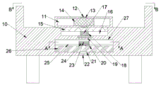
Fig. 2 is a schematic view of the structure a-a in fig. 1.
FIG. 3 is a schematic diagram of B-B in FIG. 1.
Fig. 4 is an enlarged schematic view of C in fig. 2.
Fig. 5 is an enlarged schematic view of D in fig. 2.
Detailed Description
The invention will now be described in detail with reference to fig. 1-5, wherein for ease of description the orientations described hereinafter are now defined as follows: the up, down, left, right, and front-back directions described below correspond to the up, down, left, right, and front-back directions in the projection relationship of fig. 1 itself.
The medical nursing roast lamp adjusting according to the actions of the patient, which is described in conjunction with fig. 1-5, comprises a body 10 and first detection chambers 11 symmetrically arranged in the body 10 from front to back, first sliding grooves 12 are symmetrically arranged in the upper and lower parts of the inner wall of the first detection chamber 11, first fixing blocks 13 are slidably arranged on the first sliding grooves 12, first pressure sensors 32 are arranged on the inner wall of the first detection chamber 11, first springs 33 are connected between the first pressure sensors 32 and the first fixing blocks 13, the first pressure sensors 32 can detect the position of the patient by detecting the stress, first detection blocks 14 are fixedly arranged between the first fixing blocks 13, one end of each first detection block 14 extends to the outside, second detection chambers 16 positioned at the lower side of the first detection chamber 11 are symmetrically arranged in the body 10 from front to back, second sliding grooves 18 are arranged in the second detection chambers 16, the second sliding groove 18 is provided with a second detection block 15 in a sliding manner, the upper end of the second detection block 15 extends to the outside, the second detection cavity 16 is provided with a second pressure sensor 19 in the bottom wall, a second spring 17 is connected between the second pressure sensor 19 and the second detection block 15, the second pressure sensor 19 can detect the stress to judge whether the patient turns, the machine body 10 is provided with a baking lamp cavity 27 positioned at the lower side of the second detection cavity 16, the front wall of the baking lamp cavity 27 is provided with a take-out port 29 communicated with the outside, the bottom wall of the baking lamp cavity 27 is provided with a third sliding groove 22, the third sliding groove 22 is provided with a second fixed block 21 in a sliding manner, the upper end of the second fixed block 21 is fixedly provided with a placing plate 26, the placing plate 26 is provided with a first electric sliding rail 25, the first electric sliding rail 25 is provided with a base 20 in a sliding manner, and the base 20 is provided with a height plate 23, the height plate 23 and the base 20 are connected through a hinge shaft 24, a first motor 60 is arranged on the right wall of the height plate 23, the left end of the first motor 60 is in power connection with a cam shaft 59, a cam 50 is fixedly arranged on the cam shaft 59, a fourth sliding groove 61 is symmetrically arranged in the height plate 23 in a left-right mode, a fixed plate 58 is arranged on the fourth sliding groove 61 in a sliding mode, a third spring 62 is connected between the front walls of the fixed plate 58 and the fourth sliding groove 61, the fixed plate 58 abuts against the cam 50, a moving plate 57 is fixedly arranged at the rear end of the fixed plate 58, an adjusting cavity 52 is arranged in the moving plate 57, a second motor 54 is arranged in the right wall of the adjusting cavity 52, the left end of the second motor 54 is in power connection with a gear shaft 56, a first moving plate gear 55 is fixedly arranged on the gear shaft 56, a rotating shaft 51 is rotatably arranged in the moving plate 57, the rotating shaft 51 extends into the adjusting cavity 52 and, the second gear 53 is engaged with the first gear 55, the rotating shaft 51 is fixedly provided with a rotating block 38, a fifth slide groove 49 is formed in the rotating block 38, a slide plate 48 is slidably disposed on the fifth slide groove 49, a big gear 47 is fixedly arranged at the rear end of the sliding plate 48, a screw rod 46 is connected in the big gear 47 through a thread, a push plate 42 is fixedly arranged at the rear end of the screw rod 46, a third motor 45 is arranged in the rotating block 38, the rear end of the third motor 45 is connected with a motor shaft 44 in a power mode, a third gear 43 is fixedly arranged on the motor shaft 44, the third gear 43 is engaged with the large gear 47, seventh sliding grooves 41 are symmetrically arranged in the inner wall of the rotating block 38, a top plate 40 is arranged on the seventh sliding groove 41 in a sliding manner, the top plate 40 abuts against the push plate 42, and a fourth spring 39 is connected between the top plate 40 and the rear wall of the seventh sliding groove 41.
Advantageously, the top plate 40 is fixedly provided with a connecting rod 37 at the rear end, the connecting rod 37 extends to the outside at the rear end and is fixedly provided with a baking lamp 36, and the baking lamp 36 can bake the injured part of the patient.
Advantageously, a second electric slide rail 30 is arranged on the front side of the outlet 29, and a slider 31 is slidably arranged on the second electric slide rail 30, wherein the slider 31 can control the opening and closing of the outlet 29.
Advantageously, a handle 28 is fixed to the front end of the placing plate 26, and pulling the handle 28 can move the placing plate 26.
Beneficially, a measurement cavity 70 communicated with the outside is arranged in the first detection block 14, a third electric slide rail 71 is arranged on the inner wall of the measurement cavity 70, an air cylinder 34 is slidably arranged on the third electric slide rail 71, a measurement plate 35 is fixedly arranged at the tail end of an expansion link of the air cylinder 34, and the height of the injured part of the patient can be detected through the measurement plate 35.
Sequence of mechanical actions of the whole device:
the patient lies on the device horizontally, the first detection block 14 is squeezed to enable the first fixed block 13 to slide along the first sliding chute 12 to compress the first spring 33, the second detection block 15 is pushed to slide along the second sliding chute 18 to compress the second spring 17, the second pressure sensor 19 and the first pressure sensor 32 record the initial stress, the slider 31 slides along the second electric sliding rail 30 to open the taking-out opening 29, the handle 28 is pulled to drive the placing plate 26 to move so that the second fixed block 21 slides forwards along the third sliding chute 22 and moves to the outside through the taking-out opening 29, the height plate 23 rotates along the hinge shaft 24 so that the height plate 23 is in a vertical state, the base 20 moves along the first electric sliding rail 25 to adjust the position of the baking lamp 36, the second motor 54 is started to drive the gear shaft 56, the first gear 55, the second gear 53, the rotating shaft 51 and the rotating block 38 to rotate so that the baking lamp 36 is in a horizontal state, the air cylinder 34 pushes the measurement plate 35 to move so that the measurement, the cylinder 34 slides downwards along the third electric sliding rail 71 to enable the measuring plate 35 to be in contact with a human body, so that the height of the affected part is judged, then the first motor 60 is started to drive the cam shaft 59 and the cam 50 to rotate, so that the fixing plate 58 is pushed to move upwards along the fourth sliding groove 61 to stretch the third spring 62, so that the irradiation height of the baking lamp 36 is adjusted, the treatment effect is improved, the third motor 45 is started to drive the motor shaft 44, the third gear 43 and the large gear 47 to rotate, the sliding plate 48 slides along the fifth sliding groove 49, so that the lead screw 46 drives the push plate 42 to move backwards to push the top plate 40 to slide backwards along the seventh sliding groove 41 to compress the fourth spring 39, and the connecting rod 37 is driven to move backwards so that the baking lamp 36 can be;
when a human body moves, the first detection block 14 moves along the first sliding groove 12 under the action of the first spring 33, the first pressure sensor 32 senses stress to judge the specific position of a wounded part of a patient, then the third motor 45 is started, the motor shaft 44, the third gear 43 and the large gear 47 rotate, the baking lamp 36 is aligned to the wounded part again under the action of the push plate 42 and the fourth spring 39, when the patient turns, the second detection block 15 moves upwards along the second sliding groove 18 under the action of the second spring 17, the second pressure sensor 19 senses stress to judge the turning amplitude of the patient and starts the motor shaft 44, and the motor shaft 44 drives the gear shaft 56, the first gear 55, the second gear 53, the rotating shaft 51 and the rotating block 38 to rotate so that the baking lamp 36 is aligned to the wounded part again.
The above embodiments are merely illustrative of the technical ideas and features of the present invention, and the purpose thereof is to enable those skilled in the art to understand the contents of the present invention and implement the present invention, and not to limit the protection scope of the present invention. All equivalent changes and modifications made according to the spirit of the present invention should be covered within the protection scope of the present invention.
Claims (5)
1. The utility model provides a roast lamp of medical nursing that adjusts according to patient's action, includes organism and front and back symmetry set up in first detection chamber in the organism which characterized in that: first sliding grooves are symmetrically arranged up and down on the inner wall of the first detection cavity, a first fixed block is arranged on the first sliding grooves in a sliding manner, a first pressure sensor is arranged on the inner wall of the first detection cavity, a first spring is connected between the first pressure sensor and the first fixed block, the first pressure sensor can detect stress so as to judge the position of a patient, a first detection block is fixedly arranged between the first fixed blocks, one end of the first detection block extends to the outside, second detection cavities positioned on the lower side of the first detection cavity are symmetrically arranged in the machine body front and back, a second sliding groove is arranged in the second detection cavity, a second detection block is arranged on the second sliding groove in a sliding manner, the upper end of the second detection block extends to the outside, a second pressure sensor is arranged in the bottom wall of the second detection cavity, and a second spring is connected between the second pressure sensor and the second detection block, the second pressure sensor can detect stress to judge whether the patient turns, a baking lamp cavity is arranged in the machine body and positioned on the lower side of the second detection cavity, a taking-out port communicated with the outside is arranged on the front wall of the baking lamp cavity, a third chute is arranged on the bottom wall of the baking lamp cavity, a second fixed block is arranged on the third chute in a sliding manner, a placing plate is fixedly arranged at the upper end of the second fixed block, a first electric slide rail is arranged on the placing plate, a base is arranged on the first electric slide rail in a sliding manner, a height plate is arranged in the base, the height plate is connected with the base through a hinge shaft, a first motor is arranged on the right wall of the height plate, the left end of the first motor is in power connection with a cam shaft, a cam is fixedly arranged on the cam shaft, a fourth chute is symmetrically arranged in the height plate, and a fixed plate is arranged on the, a third spring is connected between the front walls of the fixed plate and the fourth chute, the fixed plate is abutted against the cam, a movable plate is fixedly arranged at the rear end of the fixed plate, an adjusting cavity is arranged in the movable plate, a second motor is arranged in the right wall of the adjusting cavity, the left end of the second motor is in power connection with a gear shaft, a first gear is fixedly arranged on the gear shaft, a rotating shaft is rotatably arranged in the movable plate, the right end of the rotating shaft extends into the adjusting cavity and is fixedly provided with a second gear, the second gear is meshed with the first gear, a rotating block is fixedly arranged on the rotating shaft, a fifth chute is arranged in the rotating block, a sliding plate is slidably arranged on the fifth chute, a large gear is fixedly arranged at the rear end of the sliding plate, a lead screw is in threaded connection with the large gear, a push plate is fixedly arranged at the rear end of the lead screw, the rear end of the third motor is in power connection with a motor shaft, a third gear is fixedly arranged on the motor shaft and meshed with the gear wheel, seventh sliding grooves are symmetrically formed in the inner wall of the rotating block in the left-right direction, a top plate is arranged on the seventh sliding grooves in a sliding mode and abutted against the push plate, and a fourth spring is connected between the top plate and the rear wall of the seventh sliding groove.
2. The medical care searchlight of claim 1 adjusted according to patient motion, wherein: the top plate rear end is fixedly provided with a connecting rod, the connecting rod rear end extends to the outside and is fixedly provided with a baking lamp, and the baking lamp can bake the injured part of the patient.
3. The medical care searchlight of claim 1 adjusted according to patient motion, wherein: the front side of the taking-out opening is provided with a second electric slide rail, a slide block is arranged on the second electric slide rail in a sliding mode, and the slide block can control the opening and closing of the taking-out opening.
4. The medical care searchlight of claim 1 adjusted according to patient motion, wherein: the front end of the placing plate is fixedly provided with a handle, and the placing plate can be driven to move by pulling the handle.
5. The medical care searchlight of claim 1 adjusted according to patient motion, wherein: the first detection block is internally provided with a measurement cavity communicated with the outside, the inner wall of the measurement cavity is provided with a third electric slide rail, the third electric slide rail is provided with a cylinder in a sliding manner, the tail end of a telescopic rod of the cylinder is fixedly provided with a measurement plate, and the measurement plate can detect the height of the injured part of the patient.
Priority Applications (1)
| Application Number | Priority Date | Filing Date | Title |
|---|---|---|---|
| CN202110044177.1A CN112494828B (en) | 2021-01-13 | 2021-01-13 | Medical nursing baking lamp adjusted according to patient action |
Applications Claiming Priority (1)
| Application Number | Priority Date | Filing Date | Title |
|---|---|---|---|
| CN202110044177.1A CN112494828B (en) | 2021-01-13 | 2021-01-13 | Medical nursing baking lamp adjusted according to patient action |
Publications (2)
| Publication Number | Publication Date |
|---|---|
| CN112494828A true CN112494828A (en) | 2021-03-16 |
| CN112494828B CN112494828B (en) | 2022-05-24 |
Family
ID=74952239
Family Applications (1)
| Application Number | Title | Priority Date | Filing Date |
|---|---|---|---|
| CN202110044177.1A Active CN112494828B (en) | 2021-01-13 | 2021-01-13 | Medical nursing baking lamp adjusted according to patient action |
Country Status (1)
| Country | Link |
|---|---|
| CN (1) | CN112494828B (en) |
Citations (15)
| Publication number | Priority date | Publication date | Assignee | Title |
|---|---|---|---|---|
| US20060288483A1 (en) * | 2003-08-28 | 2006-12-28 | Naeslund Ingemar | Patient repositioning device and method |
| US20170065477A1 (en) * | 2011-03-15 | 2017-03-09 | Mark Jagger | Computer controlled laser therapy treatment table |
| CN206198487U (en) * | 2016-08-26 | 2017-05-31 | 李艳 | A kind of medical multi-angular is from temperature-sensitive heat lamp |
| CN207168839U (en) * | 2017-03-16 | 2018-04-03 | 廖元翠 | A kind of energy-saving surgical nursing equipment |
| CN109350860A (en) * | 2018-09-27 | 2019-02-19 | 李桂芬 | Heat lamp is used in a kind of nursing of medical surgery |
| CN109499004A (en) * | 2019-01-14 | 2019-03-22 | 常州市中医医院 | A kind of nursing heat lamp with herbal fumigation function |
| CN208726558U (en) * | 2018-04-09 | 2019-04-12 | 中国人民解放军第一五三中心医院 | A kind of new surgical heat lamp |
| CN110147124A (en) * | 2019-06-03 | 2019-08-20 | 嘉兴古辛达贸易有限公司 | A kind of optical sensor of quick detection error |
| CN209529915U (en) * | 2018-08-29 | 2019-10-25 | 上海长海医院 | A kind of exposure therapeutic device of the adjustable heat lamp position of fire victim |
| CN209824041U (en) * | 2019-03-28 | 2019-12-20 | 何红妹 | Baking lamp with adjustable distance |
| CN210186255U (en) * | 2019-04-17 | 2020-03-27 | 王咏霞 | Roast lamp device for general surgery |
| CN210845010U (en) * | 2019-09-02 | 2020-06-26 | 中国医科大学附属盛京医院 | Roast lamp device of paediatrics postoperative |
| CN111588993A (en) * | 2020-05-22 | 2020-08-28 | 朱九华 | Medical automatic position-changing baking lamp |
| CN111840826A (en) * | 2020-08-26 | 2020-10-30 | 江苏省肿瘤医院 | Special radiotherapy equipment of doctor |
| CN112022651A (en) * | 2020-09-16 | 2020-12-04 | 福州市连江县邦顺科技有限公司 | Chair for assisting lumbar muscle sprain treatment |
-
2021
- 2021-01-13 CN CN202110044177.1A patent/CN112494828B/en active Active
Patent Citations (15)
| Publication number | Priority date | Publication date | Assignee | Title |
|---|---|---|---|---|
| US20060288483A1 (en) * | 2003-08-28 | 2006-12-28 | Naeslund Ingemar | Patient repositioning device and method |
| US20170065477A1 (en) * | 2011-03-15 | 2017-03-09 | Mark Jagger | Computer controlled laser therapy treatment table |
| CN206198487U (en) * | 2016-08-26 | 2017-05-31 | 李艳 | A kind of medical multi-angular is from temperature-sensitive heat lamp |
| CN207168839U (en) * | 2017-03-16 | 2018-04-03 | 廖元翠 | A kind of energy-saving surgical nursing equipment |
| CN208726558U (en) * | 2018-04-09 | 2019-04-12 | 中国人民解放军第一五三中心医院 | A kind of new surgical heat lamp |
| CN209529915U (en) * | 2018-08-29 | 2019-10-25 | 上海长海医院 | A kind of exposure therapeutic device of the adjustable heat lamp position of fire victim |
| CN109350860A (en) * | 2018-09-27 | 2019-02-19 | 李桂芬 | Heat lamp is used in a kind of nursing of medical surgery |
| CN109499004A (en) * | 2019-01-14 | 2019-03-22 | 常州市中医医院 | A kind of nursing heat lamp with herbal fumigation function |
| CN209824041U (en) * | 2019-03-28 | 2019-12-20 | 何红妹 | Baking lamp with adjustable distance |
| CN210186255U (en) * | 2019-04-17 | 2020-03-27 | 王咏霞 | Roast lamp device for general surgery |
| CN110147124A (en) * | 2019-06-03 | 2019-08-20 | 嘉兴古辛达贸易有限公司 | A kind of optical sensor of quick detection error |
| CN210845010U (en) * | 2019-09-02 | 2020-06-26 | 中国医科大学附属盛京医院 | Roast lamp device of paediatrics postoperative |
| CN111588993A (en) * | 2020-05-22 | 2020-08-28 | 朱九华 | Medical automatic position-changing baking lamp |
| CN111840826A (en) * | 2020-08-26 | 2020-10-30 | 江苏省肿瘤医院 | Special radiotherapy equipment of doctor |
| CN112022651A (en) * | 2020-09-16 | 2020-12-04 | 福州市连江县邦顺科技有限公司 | Chair for assisting lumbar muscle sprain treatment |
Also Published As
| Publication number | Publication date |
|---|---|
| CN112494828B (en) | 2022-05-24 |
Similar Documents
| Publication | Publication Date | Title |
|---|---|---|
| CN107296707B (en) | Movable infant incubator | |
| CN211355581U (en) | Special ultrasonic examination bed capable of randomly adjusting position for children | |
| CN110840566B (en) | Guide wire clamping and twisting device of interventional operation robot | |
| CN112494828B (en) | Medical nursing baking lamp adjusted according to patient action | |
| CN206534863U (en) | A kind of intelligent temperature control bird-pecking moxibustion treats box | |
| CN110371906A (en) | A kind of vacuum blood collection tube packaging system with sterile protecting apparatus | |
| CN107137190B (en) | Baby radiation heat-insulation box | |
| CN107255718A (en) | A kind of Portable mobile phone blood glucose meter | |
| CN111458175A (en) | A detect sampling device for breast tumour | |
| CN110274700A (en) | A kind of wifi editions wireless electron Thermometer System | |
| CN213046851U (en) | Clinical pulse detection device that uses of cardiovascular internal medicine | |
| CN114767441A (en) | Comprehensive nursing device convenient for newborn pediatric department | |
| CN210056720U (en) | Automatic back patting device | |
| CN113180771A (en) | Heart radiography postoperative is with wound pressure device with regularly add decompression function | |
| CN112089443A (en) | Abdomen percussion device for internal medicine clinical examination | |
| CN112717271A (en) | Medical electrode paster with automatic unhairing function | |
| CN211385109U (en) | Clinical laboratory strorage device | |
| CN220089439U (en) | Oral cavity spreader for pediatrics | |
| CN219681120U (en) | Variable-frequency flushing device for nasal cavity | |
| CN216365691U (en) | Portable oxygen cabin | |
| CN218899400U (en) | Pediatric oral examination auxiliary device | |
| CN219480083U (en) | Respiratory sleep radar sensor | |
| CN215584083U (en) | Clinical inspection device that uses of department of general surgery | |
| CN217338693U (en) | Old person's nursing device for venipuncture | |
| CN203741962U (en) | Dry chemistry analysis urinalysis closestool |
Legal Events
| Date | Code | Title | Description |
|---|---|---|---|
| PB01 | Publication | ||
| PB01 | Publication | ||
| SE01 | Entry into force of request for substantive examination | ||
| SE01 | Entry into force of request for substantive examination | ||
| TA01 | Transfer of patent application right | ||
| TA01 | Transfer of patent application right |
Effective date of registration: 20220507 Address after: 221000 floor 2, plant 16, medical health industrial park, Xiyi high tech industrial development, Xinyi City, Xuzhou City, Jiangsu Province Applicant after: Jiangsu Kangkang classmate Technology Co.,Ltd. Address before: 201600 4-9, Lane 3088, Wenxiang Road, Songjiang New Town, Songjiang District, Shanghai Applicant before: Shanghai zhuimer Cosmetics Co.,Ltd. |
|
| GR01 | Patent grant | ||
| GR01 | Patent grant |