CN112476683A - Square wooden stock waxing machine ware - Google Patents
Square wooden stock waxing machine ware Download PDFInfo
- Publication number
- CN112476683A CN112476683A CN202011349836.4A CN202011349836A CN112476683A CN 112476683 A CN112476683 A CN 112476683A CN 202011349836 A CN202011349836 A CN 202011349836A CN 112476683 A CN112476683 A CN 112476683A
- Authority
- CN
- China
- Prior art keywords
- sliding
- bottom plate
- rack
- rotating shaft
- blank
- Prior art date
- Legal status (The legal status is an assumption and is not a legal conclusion. Google has not performed a legal analysis and makes no representation as to the accuracy of the status listed.)
- Granted
Links
Images


Classifications
-
- B—PERFORMING OPERATIONS; TRANSPORTING
- B27—WORKING OR PRESERVING WOOD OR SIMILAR MATERIAL; NAILING OR STAPLING MACHINES IN GENERAL
- B27K—PROCESSES, APPARATUS OR SELECTION OF SUBSTANCES FOR IMPREGNATING, STAINING, DYEING, BLEACHING OF WOOD OR SIMILAR MATERIALS, OR TREATING OF WOOD OR SIMILAR MATERIALS WITH PERMEANT LIQUIDS, NOT OTHERWISE PROVIDED FOR; CHEMICAL OR PHYSICAL TREATMENT OF CORK, CANE, REED, STRAW OR SIMILAR MATERIALS
- B27K5/00—Treating of wood not provided for in groups B27K1/00, B27K3/00
- B27K5/02—Staining or dyeing wood; Bleaching wood
Abstract
The invention relates to a waxing machine, in particular to a square wooden blank waxing machine. The technical problem to be solved is as follows: the utility model provides a manual work is wiped wax, and the dynamics of wiping wax is unanimous, is smeared even square wooden stock machine of waxing. The technical scheme is as follows: a square wooden blank waxing machine comprises: the top of the bottom plate is provided with an installation plate; the coloring mechanism is arranged on one side of the top of the bottom plate; the other side of the top of the bottom plate is provided with a swinging mechanism. Through the matching of the coloring mechanism and the swinging mechanism, the upper, lower, left and right surfaces of the blank can be coated with the wax oil, and workers only need to coat the wax oil on the front surface and the rear surface of the blank; the blank can be pushed to move by the arranged pushing mechanism, and workers only need to intermittently put in new blanks on the mounting plate.
Description
Technical Field
The invention relates to a waxing machine, in particular to a square wooden blank waxing machine.
Background
Carpenters often have a lot of stocks that are used for making furniture, in order to prolong the life of stock, and make the customer select the stock that is used for making furniture, when making the stock look more pleasing to the eye, need scribble waxing oil to the stock, make it seem brighter, can play the guard action to the stock simultaneously, the waxing work to the stock all is the manual work at present, the manual work is smeared waxing with the scraper blade to the stock, but the artifical dynamics of smearing at every turn is not uniform, waxing oil then can not be evenly scribbled on the stock, thereby can't play the guard work to the stock.
Therefore, the square wooden blank waxing machine which is manually and evenly used for waxing is designed.
Disclosure of Invention
In order to overcome the defects that manual force is different when the wax oil is coated every time, the wax oil cannot be uniformly coated on the blank, and the blank cannot be protected, the technical problem to be solved is as follows: the utility model provides a manual work is wiped wax, and the dynamics of wiping wax is unanimous, is smeared even square wooden stock machine of waxing.
The technical scheme is as follows: a square wooden blank waxing machine comprises:
the top of the bottom plate is provided with an installation plate;
the coloring mechanism is arranged on one side of the top of the bottom plate;
the other side of the top of the bottom plate is provided with a swinging mechanism.
Further, the coloring mechanism comprises:
the bracket is arranged on one side of the top of the bottom plate;
the first bearing seats are symmetrically arranged on one side of the top of the bottom plate;
the first rotating shaft is arranged on one side of the first bearing seat;
the middle parts of the first rotating shafts are provided with rotating shaft devices;
the bracket is uniformly and rotatably provided with a plurality of first coloring devices, and the first coloring devices on two sides are matched with the bracket in a sliding manner;
further, the swing mechanism includes:
the air cylinder is arranged on one side of the top of the bottom plate;
the cylinder telescopic rod is connected with the first rack;
the first gear is arranged on one side of the first rotating shaft and meshed with the first rack;
the first sliding blocks are arranged in the rotating shaft device in a sliding mode, and the first sliding blocks on the same side are connected with the first coloring device;
the first springs are connected between the inner side of the first sliding block and the rotating shaft device;
the first sliding rail is arranged on one side of the top of the bottom plate;
and a second sliding block is arranged on one side of the first sliding rail in a sliding manner and is in sliding fit with the first rack.
Further, still including advancing mechanism, advancing mechanism includes:
the special-shaped rod is arranged on one side of the first rack;
the second bearing seat is arranged on one side of the top of the bottom plate;
one side of the second bearing seat is provided with a second rotating shaft;
one side of the second rotating shaft is provided with a second gear, and the other side of the second rotating shaft is provided with a ratchet wheel which is matched with the special-shaped rod;
a second slide rail is arranged on one side of the top of the bottom plate;
a second rack is arranged on one side of the second sliding rail in a sliding manner;
and a second spring is connected between one end of the second rack and the inner wall of the second slide rail.
Further, still including the feed supplement mechanism, the feed supplement mechanism is including:
the third sliding rail is arranged at the top of the bracket;
a water outlet tank is arranged on one side of the third slide rail;
the top of the third slide rail is provided with a fixed rod;
the liquid tank is arranged at one end of the fixed rod;
the top of the water outlet tank is provided with a long pipe;
a lifting rod is arranged on one side of the third sliding rail in a sliding mode and matched with the first rack;
a ball, and one side of the top of the lifting rod is provided with the ball.
Further, still including stop gear, stop gear is including:
the L-shaped rod is arranged on one side of the second rack;
the mounting block is arranged on one side of the top of the bottom plate;
the sliding rod is arranged on one side of the mounting block in a sliding manner;
the third spring is connected between the sliding rod and the mounting block and is initially compressed;
a limiting block is arranged at one end of the sliding rod;
the wedge-shaped block is arranged on one side of the top of the L-shaped rod and matched with the limiting block.
Further, still including side complementary color mechanism, side complementary color mechanism is including:
a fixing plate is arranged on one side of the top of the bottom plate;
the third rotating shaft is rotatably arranged on both sides of the fixed plate;
and the second color applicator is arranged on one side of the third rotating shaft.
Further, the limiting block is provided with a disc.
The invention has the following advantages: through the matching of the coloring mechanism and the swinging mechanism, the upper, lower, left and right surfaces of the blank can be coated with the wax oil, and workers only need to coat the wax oil on the front surface and the rear surface of the blank; the blank can be pushed to move by the arranged pushing mechanism, and workers only need to intermittently put new blanks on the mounting plate; the first coloring device can be charged through the material supplementing mechanism, so that the blank coated with the wax oil has higher glossiness; the provided limiting mechanism can clamp the blank, so that the work of smearing the wax oil is facilitated; wax oil can be smeared on the front side surface and the rear side surface of the blank through the arranged side surface color complementing mechanism, so that the labor is further saved.
Drawings
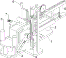
Fig. 1 is a schematic perspective view of the present invention.
FIG. 2 is a schematic view of a first partial body structure according to the present invention.
FIG. 3 is a schematic view of a second partial body structure according to the present invention.
Fig. 4 is a perspective view of a third embodiment of the present invention.
Fig. 5 is a perspective view of a fourth embodiment of the present invention.
FIG. 6 is a schematic view of a fifth partial body structure according to the present invention.
FIG. 7 is a schematic view of a sixth partial body structure according to the present invention.
FIG. 8 is a schematic view of a seventh partial body structure according to the present invention.
Wherein: 1-bottom plate, 2-mounting plate, 3-coloring mechanism, 30-bracket, 31-first bearing seat, 32-first rotating shaft, 33-rotating shaft device, 34-first coloring device, 4-swinging mechanism, 40-air cylinder, 41-first rack, 42-first gear, 43-first slide block, 44-first spring, 45-first slide rail, 46-second slide block, 5-propelling mechanism, 50-second bearing seat, 51-second slide rail, 52-second rotating shaft, 53-special-shaped rod, 54-second gear, 55-second rack, 56-second spring, 57-ratchet wheel, 6-material supplementing mechanism, 60-third slide rail, 61-water outlet box, 62-fixing rod, 63-lifting rod, 64-a liquid tank, 65-a long pipe, 66-a ball, 7-a limiting mechanism, 70-an L-shaped rod, 71-a mounting block, 72-a sliding rod, 73-a third spring, 74-a wedge block, 75-a limiting block, 8-a side color complementing mechanism, 80-a fixing plate, 81-a third rotating shaft and 82-a second color applicator.
Detailed Description
The invention is further illustrated by the following specific examples in which, unless otherwise explicitly stated and limited, terms such as: the arrangement, installation, connection are to be understood broadly, for example, they may be fixed, detachable, or integrally connected; can be mechanically or electrically connected; they may be connected directly or indirectly through intervening media, or they may be interconnected between two elements. The specific meanings of the above terms in the present invention can be understood in specific cases to those skilled in the art.
Example 1
The utility model provides a square wooden stock waxing machine, as shown in figure 1, including bottom plate 1, mounting panel 2, color mechanism 3 and swing mechanism 4, 1 top of bottom plate is equipped with mounting panel 2, and 1 top left side of bottom plate is equipped with color mechanism 3, and 1 top front side of bottom plate is equipped with swing mechanism 4.
As shown in fig. 2, the coloring mechanism 3 includes a support 30, a first bearing seat 31, a first rotating shaft 32, a rotating shaft device 33 and a first coloring device 34, the support 30 is arranged on the left side of the top of the base plate 1, the first bearing seat 31 is symmetrically arranged on the left and right sides of the top of the base plate 1, the first rotating shaft 32 is arranged on the upper side of the first bearing seat 31, the rotating shaft device 33 is arranged in the middle of the first rotating shaft 32, three first coloring devices 34 are uniformly and rotatably arranged on the support 30, and the first coloring devices 34 on the left and right sides are in sliding fit with the support 30.
As shown in fig. 3, the swing mechanism 4 includes an air cylinder 40, a first rack 41, a first gear 42, a first slider 43, a first spring 44, a first slide rail 45 and a second slider 46, the air cylinder 40 is disposed on the front side of the top of the bottom plate 1, the first rack 41 is connected to an expansion link of the air cylinder 40, the first gear 42 is disposed on the front side of the first rotating shaft 32, the first gear 42 is engaged with the first rack 41, the first slider 43 is slidably disposed in the rotating shaft 33, the first slider 43 on the same side is connected to the first color applicator 34, the first spring 44 is connected between the inner side of the first slider 43 and the rotating shaft 33, the first slide rail 45 is disposed on the front side of the top of the bottom plate 1, the second slider 46 is slidably disposed on the upper side of the first slide rail 45, and the second slider 46 is slidably engaged with the first rack 41.
When the surface of the square wooden blank needs to be smeared with wax oil to make the blank more attractive and prolong the service life of the blank, a worker can slide the blank from the right side to the left side of the top of the mounting plate 2, so that the upper side and the lower side of the blank can be smeared with wax oil under the action of the first coloring device 34, then the air cylinder 40 is started to work, the telescopic rod of the air cylinder 40 extends to drive the first rack 41 to move downwards, the first rack 41 moves downwards to drive the second sliding block 46 to move downwards, the first rack 41 moves downwards after the second sliding block 46 moves to the lowest side, at the moment, the second sliding block 46 can guide the first rack 41, the first rack 41 moves downwards to drive the first rotating shaft 32 to rotate through the first gear 42, the first rotating shaft 32 rotates to drive the rotating shaft 33 to rotate, so that the first coloring devices 34 on the left side and the right side approach each other along with the rotation, when the blank slides to the upper side on the bracket 30, the first sliding blocks 43 are close to each other, the first springs 44 are compressed, the first coloring devices 34 on the left side and the right side are close to each other along with rotation, so that the left side and the right side of the blank can be uniformly coated with the wax oil, then the first rack 41 can be moved upwards through the air cylinder 40, the first rack 41 is moved upwards until being in contact with the second sliding block 46 and then continuously moves, so that the second sliding block 46 is driven to move upwards to reset, the first rack 41 moves upwards to drive the first rotating shaft 32 to rotate through the first gear 42, meanwhile, the first coloring devices 34 on the left side and the right side can be moved to reset under the action of the first springs 44, then, the air cylinder 40 can be stopped to work, a worker can take the blank down, the front side and the rear side of the blank can be coated with the wax oil, and when the blank needs to be coated with the wax oil, the steps can be repeated.
Example 2
On the basis of embodiment 1, as shown in fig. 4, the present invention further includes a pushing mechanism 5, the pushing mechanism 5 includes a second bearing seat 50, a second sliding rail 51, a second rotating shaft 52, a special-shaped rod 53, a second gear 54, a second rack 55, a second spring 56 and a ratchet 57, the special-shaped rod 53 is disposed on the right side of the first rack 41, the second bearing seat 50 is disposed on the right rear side of the top of the bottom plate 1, the second rotating shaft 52 is disposed on the upper side of the second bearing seat 50, the second gear 54 is disposed on the rear side of the second rotating shaft 52, the ratchet 57 is disposed on the front side of the second rotating shaft 52, the ratchet 57 is matched with the special-shaped rod 53, the second sliding rail 51 is disposed on the right side of the top of the bottom plate 1, the second rack 55 is slidably disposed on the right side of the second sliding rail 51, the second spring 56 is connected between the right end.
When the first rack 41 moves downwards, the worker can also put the blank to be waxed on the right side of the top of the mounting plate 2 at the same time, place the collecting frame on the left side of the bottom plate 1, the first rack 41 moves downwards to drive the special-shaped rod 53 to move downwards, at the moment, the special-shaped rod 53 does not drive the ratchet wheel 57 to rotate, then, the first rack 41 moves upwards to drive the special-shaped rod 53 to move upwards to contact with a plurality of wheels and then move continuously, so as to drive the ratchet wheel 57 to rotate, at the moment, the first coloring devices 34 on the left side and the right side are reset, the ratchet wheel 57 rotates to drive the second gear 54 to rotate through the second rotating shaft 52, the second gear 54 rotates to drive the second rack 55 to move leftwards, the second spring 56 is stretched, the second rack 55 moves leftwards to push the blank to be waxed to move leftwards, the blank to be waxed can be positioned on the left side of the top of the mounting plate 2, the blank to be waxed also push the blank, the blank to be waxed moves leftwards and can be waxed on the upper side face and the lower side face through the first coloring device 34, when the special-shaped rod 53 moves upwards to be not in contact with the ratchet wheel 57, the second rack 55 moves rightwards to reset under the action of the second spring 56, then the telescopic rod of the air cylinder 40 can be stretched again, when a worker only needs to move downwards through the first rack 41, the blank to be waxed is placed on the right side of the top of the mounting plate 2, the work of waxing the blank can be continuously performed, finally, the work of the air cylinder 40 is stopped, the worker can take out the blank in the collecting frame, and the waxing oil work of the front side face and the rear side face is performed.
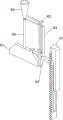
As shown in fig. 5 and 6, the feed supplementing mechanism 6 further includes a feed supplementing mechanism 6, the feed supplementing mechanism 6 includes a third slide rail 60, a water outlet tank 61, a fixing rod 62, a lifting rod 63, a liquid tank 64, a long pipe 65 and a ball 66, the third slide rail 60 is disposed at the top of the bracket 30, the water outlet tank 61 is disposed at the rear side of the third slide rail 60, the fixing rod 62 is disposed at the top of the third slide rail 60, the liquid tank 64 is disposed at the rear end of the fixing rod 62, the long pipe 65 is disposed at the top of the water outlet tank 61, the lifting rod 63 is slidably disposed at the upper side of the third slide rail 60, the lifting rod 63 is engaged with the first rack 41, and.
The worker can pour the wax oil into the liquid tank 64, the first rack 41 moves downwards without contacting with the lifting rod 63, so that the wax oil moves downwards under the action of the gravity of the worker, the lifting rod 63 moves downwards to drive the round ball 66 to move downwards, the round ball 66 moves downwards without blocking the liquid outlet of the liquid tank 64, the wax oil falls downwards and uniformly falls on the blank through the long pipe 65 and the water outlet tank 61, meanwhile, the feeding work can be carried out on the first coloring device 34, so that the blank coated with the wax oil has higher glossiness, then, when the first rack 41 moves upwards to contact with the lifting rod 63, the lifting rod 63 is driven to move upwards, the lifting rod 63 moves upwards to drive the round ball 66 to move upwards, the round ball 66 moves upwards to block the liquid outlet of the liquid tank 64, so that the automatic blanking of the wax oil and the feeding work on the first coloring device 34 can be realized, the blanking amount of each blanking is consistent, preventing waste.
As shown in fig. 7, the positioning device further comprises a limiting mechanism 7, the limiting mechanism 7 comprises an L-shaped rod 70, an installation block 71, a sliding rod 72, a third spring 73, a wedge block 74 and a limiting block 75, the L-shaped rod 70 is arranged on the rear side of the left portion of the second rack 55, the installation block 71 is arranged on the rear side of the left portion of the top of the bottom plate 1, the sliding rod 72 is arranged on the upper side of the installation block 71 in a sliding manner, the third spring 73 is connected between the sliding rod 72 and the installation block 71, the third spring 73 is initially compressed, the limiting block 75 is arranged at the front end of the sliding rod 72, the wedge block 74 is arranged on the left side of the top of the L-shaped.
The second rack 55 moves leftwards to drive the L-shaped rod 70 to move leftwards, the L-shaped rod 70 moves leftwards to drive the wedge block 74 to move leftwards to separate from the limit block 75, so that the slide rod 72 and the limit block 75 move backwards to reset under the action of the third spring 73, meanwhile, a new blank moves to the front side of the limit block 75, and after the second rack 55 moves rightwards to reset, the limit block 75 moves forwards through the wedge block 74, the third spring 73 is compressed, the limit block 75 moves forwards to fix the blank, and the waxing oil work on the blank is facilitated.
As shown in fig. 8, the color correction device further includes a side color correction mechanism 8, the side color correction mechanism 8 includes a fixing plate 80, a third rotating shaft 81 and a second color applicator 82, the fixing plate 80 is disposed on the left side of the top of the bottom plate 1, the third rotating shaft 81 is rotatably disposed on the front side and the rear side of the fixing plate 80, and the second color applicator 82 is disposed on the upper side of the third rotating shaft 81.
When the blank to be waxed moves leftwards to push the waxed blank to move leftwards, under the action of the second coloring device 82, the wax oil can be smeared on the front side surface and the rear side surface of the waxed blank, so that the blank is smeared with the wax oil in all directions and then falls into the collecting frame, and a worker can directly collect and place the blank.
The embodiments described above are provided to enable persons skilled in the art to make or use the invention and that modifications or variations can be made to the embodiments described above by persons skilled in the art without departing from the inventive concept of the present invention, so that the scope of protection of the present invention is not limited by the embodiments described above but should be accorded the widest scope consistent with the innovative features set forth in the claims.
Claims (8)
1. The utility model provides a square wooden stock waxing machine which characterized in that, including:
the top of the bottom plate (1) is provided with a mounting plate (2);
the coloring mechanism (3) is arranged on one side of the top of the bottom plate (1);
the other side of the top of the bottom plate (1) is provided with a swinging mechanism (4).
2. A square wooden blank waxing machine according to claim 1, wherein the coloring mechanism (3) comprises:
the support (30) is arranged on one side of the top of the bottom plate (1);
the first bearing seat (31) is symmetrically arranged on one side of the top of the bottom plate (1);
a first rotating shaft (32) is arranged on one side of the first bearing seat (31);
the middle parts of the rotating shafts (33) and the first rotating shaft (32) are provided with the rotating shafts (33);
the bracket (30) is uniformly and rotatably provided with a plurality of first coloring devices (34), and the first coloring devices (34) on two sides are in sliding fit with the bracket (30).
3. A square wooden blank waxing machine according to claim 1, wherein said oscillating mechanism (4) comprises:
the air cylinder (40) is arranged on one side of the top of the bottom plate (1);
the telescopic rod of the air cylinder (40) is connected with the first rack (41);
the first gear (42) is arranged on one side of the first rotating shaft (32), and the first gear (42) is meshed with the first rack (41);
the first sliding blocks (43) are arranged in the rotating shaft device (33) in a sliding mode, and the first sliding blocks (43) on the same side are connected with the first coloring device (34);
the first spring (44) is connected between the inner side of the first sliding block (43) and the rotating shaft device (33);
a first sliding rail (45), wherein the first sliding rail (45) is arranged on one side of the top of the bottom plate (1);
a second sliding block (46) is arranged on one side of the first sliding rail (45) in a sliding mode, and the second sliding block (46) is matched with the first rack (41) in a sliding mode.
4. A square wooden blank waxing machine according to claim 2, further comprising a propelling mechanism (5), wherein said propelling mechanism (5) comprises:
a special-shaped rod (53), wherein the special-shaped rod (53) is arranged on one side of the first rack (41);
a second bearing seat (50), wherein one side of the top of the bottom plate (1) is provided with the second bearing seat (50);
a second rotating shaft (52), wherein one side of the second bearing seat (50) is provided with the second rotating shaft (52);
a second gear (54), wherein one side of the second rotating shaft (52) is provided with the second gear (54), the other side of the second rotating shaft (52) is provided with a ratchet wheel (57), and the ratchet wheel (57) is matched with the special-shaped rod (53);
a second sliding rail (51), wherein the second sliding rail (51) is arranged on one side of the top of the bottom plate (1);
a second rack (55), wherein one side of the second sliding rail (51) is provided with the second rack (55) in a sliding manner, and the second rack (55) is meshed with the second gear (54);
and a second spring (56) is connected between one end of the second rack (55) and the inner wall of the second sliding rail (51).
5. A square wooden blank waxing machine according to claim 3, further comprising a feeding mechanism (6), wherein the feeding mechanism (6) comprises:
the top of the bracket (30) is provided with a third slide rail (60);
a water outlet tank (61) is arranged on one side of the third slide rail (60);
the top of the third sliding rail (60) is provided with a fixed rod (62);
a liquid tank (64), wherein one end of the fixed rod (62) is provided with the liquid tank (64);
the top of the long pipe (65) and the water outlet tank (61) is provided with the long pipe (65);
the lifting rod (63) is arranged on one side of the third sliding rail (60) in a sliding mode, and the lifting rod (63) is matched with the first rack (41);
a round ball (66), and a round ball (66) is arranged on one side of the top of the lifting rod (63).
6. The square wood blank waxing machine according to claim 4, further comprising a limiting mechanism (7), wherein the limiting mechanism (7) comprises:
an L-shaped rod (70), wherein one side of the second rack (55) is provided with the L-shaped rod (70);
the mounting block (71), and the mounting block (71) is arranged on one side of the top of the bottom plate (1);
a sliding rod (72) is arranged on one side of the mounting block (71) in a sliding manner;
a third spring (73), wherein the third spring (73) is connected between the sliding rod (72) and the mounting block (71), and the third spring (73) is initially compressed;
a limiting block (75), wherein one end of the sliding rod (72) is provided with the limiting block (75);
wedge block (74) is arranged on one side of the top of L-shaped rod (70), and wedge block (74) is matched with limiting block (75).
7. A square wooden blank waxing machine according to claim 5, further comprising a side color complementing mechanism (8), wherein the side color complementing mechanism (8) comprises:
a fixing plate (80), wherein the fixing plate (80) is arranged on one side of the top of the bottom plate (1);
the third rotating shaft (81) is rotatably arranged on both sides of the fixed plate (80);
and the second coloring device (82) is arranged on one side of the third rotating shaft (81).
8. A square wooden blank waxing machine according to claim 4, wherein: the limiting block (75) is provided with a disc.
Priority Applications (1)
| Application Number | Priority Date | Filing Date | Title |
|---|---|---|---|
| CN202011349836.4A CN112476683B (en) | 2020-11-26 | 2020-11-26 | Square wooden stock waxing machine ware |
Applications Claiming Priority (1)
| Application Number | Priority Date | Filing Date | Title |
|---|---|---|---|
| CN202011349836.4A CN112476683B (en) | 2020-11-26 | 2020-11-26 | Square wooden stock waxing machine ware |
Publications (2)
| Publication Number | Publication Date |
|---|---|
| CN112476683A true CN112476683A (en) | 2021-03-12 |
| CN112476683B CN112476683B (en) | 2022-11-04 |
Family
ID=74935151
Family Applications (1)
| Application Number | Title | Priority Date | Filing Date |
|---|---|---|---|
| CN202011349836.4A Active CN112476683B (en) | 2020-11-26 | 2020-11-26 | Square wooden stock waxing machine ware |
Country Status (1)
| Country | Link |
|---|---|
| CN (1) | CN112476683B (en) |
Cited By (2)
| Publication number | Priority date | Publication date | Assignee | Title |
|---|---|---|---|---|
| CN113059281A (en) * | 2021-03-26 | 2021-07-02 | 易德文 | Laser cutting device with function is collected to sweeps |
| CN113290647A (en) * | 2021-05-07 | 2021-08-24 | 齐德明 | Industrial production composite board equipment |
Citations (4)
| Publication number | Priority date | Publication date | Assignee | Title |
|---|---|---|---|---|
| BE650815A (en) * | 1963-08-02 | 1964-11-16 | ||
| CN104174552A (en) * | 2014-07-29 | 2014-12-03 | 宁波信泰机械有限公司 | Full-automatic rubber sleeve replacement device |
| CN104525431A (en) * | 2014-12-20 | 2015-04-22 | 华南理工大学 | Automatic equipment for coating surfaces of iron rings by glue |
| CN108160391A (en) * | 2017-12-26 | 2018-06-15 | 孙梦 | A kind of trolley case production smears equipment with pull rod surface lubrication oil |
-
2020
- 2020-11-26 CN CN202011349836.4A patent/CN112476683B/en active Active
Patent Citations (4)
| Publication number | Priority date | Publication date | Assignee | Title |
|---|---|---|---|---|
| BE650815A (en) * | 1963-08-02 | 1964-11-16 | ||
| CN104174552A (en) * | 2014-07-29 | 2014-12-03 | 宁波信泰机械有限公司 | Full-automatic rubber sleeve replacement device |
| CN104525431A (en) * | 2014-12-20 | 2015-04-22 | 华南理工大学 | Automatic equipment for coating surfaces of iron rings by glue |
| CN108160391A (en) * | 2017-12-26 | 2018-06-15 | 孙梦 | A kind of trolley case production smears equipment with pull rod surface lubrication oil |
Cited By (4)
| Publication number | Priority date | Publication date | Assignee | Title |
|---|---|---|---|---|
| CN113059281A (en) * | 2021-03-26 | 2021-07-02 | 易德文 | Laser cutting device with function is collected to sweeps |
| CN113059281B (en) * | 2021-03-26 | 2023-12-26 | 易德文 | Laser cutting device with sweeps collection function |
| CN113290647A (en) * | 2021-05-07 | 2021-08-24 | 齐德明 | Industrial production composite board equipment |
| CN113290647B (en) * | 2021-05-07 | 2022-07-08 | 临沂六娃木业有限公司 | Industrial production composite board equipment |
Also Published As
| Publication number | Publication date |
|---|---|
| CN112476683B (en) | 2022-11-04 |
Similar Documents
| Publication | Publication Date | Title |
|---|---|---|
| CN112476683A (en) | Square wooden stock waxing machine ware | |
| CN208991123U (en) | Glazer oiling station | |
| CN205085834U (en) | Slidable is burnishing machine of spraying brightener in advance | |
| CN112916291A (en) | Wood floor waxing oil device for house decoration | |
| CN209579134U (en) | A kind of H profile steel component abrasive cleaning machine | |
| CN115383529B (en) | Smoothing device for vent hole part of automobile brake disc | |
| CN210970996U (en) | Self-service car washing station | |
| CN107790322A (en) | A kind of film glue application device | |
| CN209681929U (en) | A kind of polishing fixed platform convenient for adjusting stone material angle position | |
| CN208681298U (en) | A kind of automatic edger promotes the mobile mechanism of cotton piece buff service efficiency | |
| CN210209902U (en) | Metal rust removal device | |
| CN208841144U (en) | A kind of bamboo-wood composite floor of container has the burnishing device of multidirectional adjustment structure | |
| CN209352146U (en) | A kind of turning plate rotating plate all-in-one machine | |
| CN113664669A (en) | Be used for simple plane frame solder joint equipment of polishing | |
| CN210589608U (en) | Cutter washing device for automatic edge pasting machine | |
| CN208485375U (en) | One kind using printing machine based on face fabric for automobile seat production | |
| CN109483370B (en) | Surface treatment process for new alloy material | |
| CN207558227U (en) | A kind of vehicle teaching virtual driving platform | |
| CN207507746U (en) | A kind of glue recovering mechanism | |
| CN112706053A (en) | Round steel cinder excircle burnishing machine | |
| CN220446120U (en) | Printing ink scraper polishing machine | |
| CN208614509U (en) | Polishing machine is used in engineering plastic gear processing | |
| CN207127703U (en) | A kind of water spray polishing machine for electric power storage pool surface | |
| CN207449144U (en) | A kind of 3D printer platform cleaning device | |
| CN112171409A (en) | Automatic grinding, painting and repairing equipment for moldy ceiling |
Legal Events
| Date | Code | Title | Description |
|---|---|---|---|
| PB01 | Publication | ||
| PB01 | Publication | ||
| SE01 | Entry into force of request for substantive examination | ||
| SE01 | Entry into force of request for substantive examination | ||
| TA01 | Transfer of patent application right |
Effective date of registration: 20221019 Address after: No. 27, Cangxi Road, Economic Development Zone, Gaochun District, Nanjing, Jiangsu 210000 Applicant after: Nanjing Shuangwei Packaging Technology Co.,Ltd. Address before: 511400 room 2026, building 31, 238, Lianlu Xinqiao village, dalongjie City, Panyu District, Guangzhou City, Guangdong Province Applicant before: Mo Jinque |
|
| TA01 | Transfer of patent application right | ||
| GR01 | Patent grant | ||
| GR01 | Patent grant |