Ore classification soil treatment device
Technical Field
The invention belongs to the field of ore processing, and particularly relates to an ore grading soil treatment device.
Background
Ore refers to rock removed from a passing mine that contains certain valuable minerals. It can be used in the engineering fields of metal mine, metallurgical industry, chemical industry, building industry, iron (highway) road construction unit, cement industry, sandstone industry and the like. The ore needs to be crushed, ground and the like in the production process.
Wherein the ore grading device is used for grading the ore after the coal mine stone is crushed. Traditional ore grading plant can't thoroughly break up the ore of mutual adhesion in the classification process, leads to hierarchical treatment effeciency low. And the volume of the ore adhered together is large, so that large impact can be caused to equipment in the grading process, and the failure rate of the equipment is increased. During the grading treatment process, ores can be conveyed and screened in a vibrating manner, a large amount of dust can be generated, and air pollution is caused;
wherein can produce a large amount of powders after the coal ore is smashed, because the coal ore powder has the calorific value of burning production equally, consequently can collect the coal mine powder and have higher value of utilizing, wherein at present oil exploitation's in-process, can cause certain polluting nature to soil, after oil is mixed in earth, can't separate to cause serious pollution for soil.
Therefore, it is necessary to design a device for treating soil by ore classification to solve the above technical problems.
Disclosure of Invention
In order to solve the problems, the invention provides an ore grading soil treatment device, which can be used for grading coal mine stones through a cleaning assembly, a scattering assembly and a grading assembly, mixing soil polluted by petroleum in powder of the coal mine stones through a mixing and pressing assembly, further treating the polluted soil through subsequent combustion, and greatly improving the treatment efficiency of the sludge.
The invention is realized by the following technical scheme:
an ore grading soil treatment device comprises a cleaning assembly, a scattering assembly, a grading assembly and a mixing and compacting assembly;
the cleaning assembly comprises a water outlet hole, a mud discharging hole, a cleaning assembly shell, a conveying assembly and a filter screen; a first support is arranged below the cleaning component shell, the cleaning component shell is arranged in an inclined mode, and an included angle formed by a central axis of the cleaning component shell and a horizontal plane is 10-25 degrees;
a water injection pipe is arranged at the upper end of the inner wall of the cleaning component shell, a plurality of groups of water outlet holes are formed in the water injection pipe, and the water outlet holes are distributed at equal intervals along the central axis direction of the cleaning component shell; one end of the water injection pipe penetrates to the outside of the cleaning assembly shell;
the bottom end of the inner wall of the shell of the cleaning component is provided with a plurality of groups of sludge discharge holes; the bottom end in the cleaning component shell is provided with a filter screen which is positioned above the plurality of groups of sludge discharge holes; a sludge discharge pipe is arranged below the groups of sludge discharge holes, and the groups of sludge discharge holes are communicated with the sludge discharge pipe;
one end of the sludge discharge pipe penetrates to the outer side of the cleaning assembly shell; the spiral conveying shaft of the conveying assembly is positioned inside the cleaning assembly shell;
a first feeding groove is formed above one end of the cleaning assembly shell, the first feeding groove is located at one lower end of the cleaning assembly shell, and the first feeding groove is communicated with the interior of the cleaning assembly shell;
a first discharge hole is formed in the lower portion of one end of the cleaning assembly shell, the first discharge hole is located in one end of the high position of the cleaning assembly shell, and the first discharge hole is communicated with the interior of the cleaning assembly shell;
the first discharge port is positioned above the scattering assembly and communicated with the feed end of the scattering assembly; the scattering assembly is positioned above the grading assembly, and the discharge end of the scattering assembly is communicated with the feed end of the grading assembly;
the mixing and compressing assembly comprises a compressing module, a discharging module and a stirring and conveying module;
the stirring and conveying module is arranged at the top of the pressing module, a stirring cavity is arranged in the stirring and conveying module, a conveying pipe is arranged at the bottom of the stirring and conveying module, a spiral stirrer rotating in the conveying pipe is arranged in the stirring cavity, a connecting pipe is arranged at one side of the stirring and conveying module, and a drain pipe is arranged at the other side of the stirring and conveying module;
compress tightly the module and be provided with one and compress tightly the chamber, the conveyer pipe stretches into compress tightly the intracavity, it is provided with one to compress tightly the intracavity gliding roof pressure lid on the conveyer pipe, be provided with on the roof pressure pole the round with the corresponding earth conveyer pipe 55 of conveyer pipe, be provided with an earth delivery hole on the earth conveyer pipe respectively, it sets up to compress tightly the module row material module is last, arrange material module on be provided with one with compress tightly the corresponding conveyer trough in chamber, be provided with a gliding first clamp plate and second clamp plate in the conveyer trough, the powder that hierarchical subassembly produced is adsorbed to the connecting pipe.
Preferably, two ends of the spiral conveying shaft are rotatably connected with two ends of the inner wall of the cleaning component shell through bearings, and one end of the spiral conveying shaft movably penetrates through the side wall of one end of the cleaning component shell;
an output shaft of a servo motor in the conveying assembly is in transmission connection with one end of the spiral conveying shaft through a coupler; a first platform is arranged at one end of the cleaning component shell; the servo motor is installed on the first platform.
Preferably, the filter screen comprises an outer frame and a filter mesh sheet; the filter screen is installed wash the inside bottom of subassembly shell, a plurality of groups filter screen piece evenly distributed be in on the axis of frame, and a plurality of groups filter screen piece and a plurality of groups sludge discharge hole one-to-one.
Preferably, the breaking assembly comprises a second feeding groove, a second bracket, a first reciprocating motor and a first transmission rod;
the upper opening of the second feeding groove is communicated with the first discharging hole; a stop lever is arranged in the second feeding groove, and the stop lever has an upper layer and a lower layer;
a second support is arranged below the second feeding groove, and the second feeding groove is in transmission connection with the second support through a chain rod;
a second platform is arranged at the bottom of the second support, and the first reciprocating motor is mounted on the second platform; and the output end of the first reciprocating motor is in transmission connection with the lower part of the second feeding groove through a first transmission rod.
Preferably, the grading component comprises a grading plate, a sieve plate, a third bracket and a second reciprocating motor; the third support is arranged at the bottom of the grading plate;
the grading plate is obliquely arranged, an included angle between the central axis of the grading plate and the horizontal plane is 20-25 degrees, and the discharge end of the scattering assembly is positioned above one end of the high part of the grading assembly;
the sieve plate is provided with a first sieve hole, a second sieve hole and a third sieve hole; the first sieve hole is positioned on one side of the second sieve hole, and the third sieve hole is positioned on one side of the second sieve hole far away from the first sieve hole; the mesh apertures at the first mesh, the second mesh and the third mesh are sequentially increased;
one end of the sieve plate is in transmission connection with the second reciprocating motor through a second transmission rod; a third platform is arranged at the bottom of the third support, and the third reciprocating motor is installed on the third platform;
the grading plate is in transmission connection with the sieve plate through a spring, three groups of second discharge holes are formed in the bottom of the grading plate, and the second discharge holes are respectively located below the first sieve holes, the second sieve holes and the third sieve holes;
the screen plate is provided with dust collecting holes arranged side by side, the screen plate is internally provided with a plurality of rows of dust collecting pipes, the dust collecting holes are respectively communicated with the dust collecting pipes correspondingly, and the dust collecting pipes are respectively connected on the connecting pipes.
Preferably, the grading component further comprises a first baffle, a second baffle and a third discharge hole; the two sides of the grading plate are provided with first baffles, and the two sides of the sieve plate are provided with second baffles; and the lower end of the sieve plate is provided with the third discharge hole.
Preferably, the second discharge hole comprises a second discharge hole upper part, a second discharge hole lower part, a hook and a second hanging rod; the bottom surface of the upper part of the second discharge hole is hinged with the bottom surface of the lower part of the second discharge hole;
a first hanging rod is arranged on one side of the lower part of the second discharge port, which is close to the upper part of the second discharge port, and a plurality of groups of second hanging rods are arranged on one side of the upper part of the second discharge port, which is close to the lower part of the second discharge port; the first hanging rod is movably connected with the second hanging rod through a hook.
Preferably, an air aspirator is arranged on the stirring and conveying module, the air aspirator 45 adsorbs wind power generated by the connecting pipe and conveys the wind power into the stirring cavity, a stirring frame rotating in the stirring cavity is arranged on the screw conveyor, and a motor driving the screw stirrer to rotate is arranged at the top of the stirring and conveying module.
Preferably, the pressing cavity and the jacking cover are respectively arranged in a circular shape, the pressing cover and the pressing cavity are in sealed connection, 4 telescopic sliding blocks which are correspondingly and crossly arranged are arranged on the jacking cover, 4 first gears driven by a motor are arranged in the pressing module, and tooth sockets correspondingly meshed with the first gears are arranged on the telescopic sliding blocks;
the soil conveying pipes respectively slide on the top pressure covers, the top of each top pressure cover is provided with a spring slide block, each spring slide block is provided with a reset spring, and the reset springs are respectively and fixedly connected to the top pressure covers;
the discharging module is provided with a first hydraulic rod for controlling the first pressing plate to slide, and the discharging module is provided with a second hydraulic rod for controlling the second pressing plate to slide.
Compared with the prior art, the invention has the beneficial effects that:
1. the grading device provided by the invention is provided with the cleaning component and the scattering component, and the cleaning component washes the ore, so that the problem of dust pollution in the ore processing process is solved; the scattering component scatters the adhered ores to separate, so that the grading treatment efficiency is improved, and the damage to equipment caused by large-size ores is avoided.
2. The baffles are respectively arranged on the two sides of the grading plate and the sieve plate, so that ores on the grading plate or the sieve plate are limited, and the ores are prevented from scattering.
3. Through setting up the buffer layer on to first discharge gate, can cushion the ore of the first discharge gate of will flowing through, solved the ore and can cause the problem of great impact to equipment.
4. Through setting up a plurality of groups of second peg and first peg to the second discharge gate, the moving direction of accessible second discharge gate change ore ensures that the moving direction of ore is unanimous with transfer direction of transfer apparatus, has solved the problem that the ore scatters and causes the impact to transfer apparatus.
5. Can collect coal mine stone powder through the dust collecting hole, can carry coal mine stone powder through the dust absorption pipe, further carry the stirring carry the module in after, can stir it, then in further carrying compresses tightly the module, can carry coal mine stone powder with the earth that oil pollutes in through the earth connecting pipe, and then can mix with the earth that oil pollutes in coal mine stone powder, through subsequent great improvement after the burning the treatment effeciency to coal mine stone powder.
Drawings
In order to more clearly illustrate the embodiments of the present invention or the technical solutions in the prior art, the drawings used in the description of the embodiments or the prior art will be briefly described below, and it is obvious that the drawings in the following description are some embodiments of the present invention, and those skilled in the art can also obtain other drawings according to the drawings without creative efforts.
FIG. 1 is a schematic front view of a grading apparatus according to an embodiment of the present invention;
FIG. 2 shows a schematic partial block diagram of a staging device cleaning assembly according to an embodiment of the invention;
FIG. 3 illustrates a schematic top view of a classifier screen according to an embodiment of the present invention;
FIG. 4 is a schematic front view of a grading apparatus break-up assembly according to an embodiment of the invention;
FIG. 5 shows a schematic structural view of a second feed chute of an embodiment of the invention;
FIG. 6 illustrates a front view structural schematic diagram of a grading component of a grading apparatus of an embodiment of the invention;
fig. 7 shows a schematic structural view of a screen plate of a classifying device according to an embodiment of the present invention;
FIG. 8 is a schematic structural view of a discharge port of a classifying device according to an embodiment of the present invention;
figure 9 shows a schematic view of the overall structure of a screening deck of an embodiment of the invention;
FIG. 10 is a schematic diagram illustrating the overall construction of a hybrid compression assembly in accordance with an embodiment of the present invention;
FIG. 11 is a schematic view showing the overall structure of a soil transporting pipe according to an embodiment of the present invention;
FIG. 12 is a schematic diagram showing the overall structure of a discharging module according to an embodiment of the invention;
fig. 13 is a schematic view showing the overall structure of the compression module according to the embodiment of the present invention.
In the figure: 1. cleaning the assembly; 2. breaking up the assembly; 3. a grading component; 4. cleaning the component housing; 5. a first feed chute; 6. A first discharge port; 7. A first platform; 8. a servo motor; 9. a water outlet hole; 10. a water injection pipe; 11. a sludge discharge hole; 12. a sludge discharge pipe; 13. a screw conveying shaft; 14. a first bearing; 15. a second bearing; 16. a first bracket; 17. filtering with a screen; 1701. an outer frame; 1702. a filter mesh sheet; 18. a second feed chute; 19. a stop lever; 20. a chain bar; 21. a second bracket; 22. a second platform; 23. a first reciprocating motor; 24. a first drive lever; 25. A grading plate; 26. a first baffle plate; 27. a spring; 28. a sieve plate; 29. a second baffle; 30. a third support; 31. a third platform; 32. a second reciprocating motor; 33. a second transmission rod; 34. a second discharge port; 3401. the upper part of the second discharge hole; 3402. the lower part of the second discharge hole; 35. a first screen aperture; 36. a second screen aperture; 37. a third screen aperture; 38. a third discharge port; 39. a first hanging rod; 40. hooking; 41. the second hanging rod, 42 dust collecting holes, 43 dust collecting pipes, 44 connecting pipes, 45 air aspirators, 46 stirring cavities, 47 spiral stirrers, 48 stirring frames, 49 drain pipes, 50 conveying pipes, 51 pressing cavities, 52 top pressing covers, 53 telescopic sliding blocks, 54 first gears, 55 soil conveying pipes, 56 conveying grooves, 57 first pressing plates, 58 first hydraulic rods, 59 soil conveying holes, 60 elastic sliding blocks, 61 return springs, 62 soil connecting pipes, 63 discharging modules, 64 pressing modules, 65 stirring conveying modules, 66 second pressing plates and 67 second hydraulic rods.
Detailed Description
In order to make the objects, technical solutions and advantages of the embodiments of the present invention clearer, the technical solutions in the embodiments of the present invention will be clearly and completely described below with reference to the drawings in the embodiments of the present invention, and it is obvious that the described embodiments are some, but not all, embodiments of the present invention. All other embodiments, which can be derived by a person skilled in the art from the embodiments given herein without making any creative effort, shall fall within the protection scope of the present invention.
As shown in fig. 1 to 13, an ore grading soil treatment device according to an embodiment of the present invention includes a cleaning assembly 1, a scattering assembly 2, a grading assembly 3, and a mixing and compacting assembly; illustratively, as shown in fig. 1, the cleaning assembly 1 is located above the scattering assembly 2, a discharge port of the cleaning assembly 1 is communicated with a feed port of the scattering assembly 2, ore is conveyed to the interior of the cleaning assembly 1 through the feed port of the cleaning assembly 1, the cleaning assembly 1 can remove dust and pre-scatter the ore, and the treated ore is conveyed to the scattering assembly 2.
Break up subassembly 2 and be located grading subassembly 3's top, just break up subassembly 2's discharge gate with grading subassembly 3's feed inlet intercommunication, break up subassembly 2 and be used for thoroughly breaking up the ore to carry the ore after handling extremely in the grading subassembly 3, grading subassembly 3 is used for carrying out the hierarchical processing to the ore.
The cleaning assembly 1 can wash silt in the ore, so that dust is effectively prevented from diffusing, and the environment is protected; the scattering component 2 can scatter the adhered ores thoroughly, and is favorable for improving the accuracy of grading treatment.
The cleaning assembly 1 comprises a cleaning assembly shell 4, a first feeding groove 5, a first discharging hole 6 and a spiral conveying shaft 13; illustratively, as shown in fig. 2 and 3, a first bracket 16 is arranged at the bottom of the cleaning assembly housing 4, the cleaning assembly housing 4 is arranged obliquely, and an included angle between a central axis of the cleaning assembly housing 4 and a horizontal plane is 10-25 °.
A first feeding groove 5 is arranged above one end of the cleaning component shell 4, the upper opening of the first feeding groove 5 is larger than the lower opening of the first feeding groove, the first feeding groove 5 is positioned at one end of the lower part of the cleaning component shell 4, and the first feeding groove 5 is communicated with the interior of the cleaning component shell 4; wash subassembly shell 4's other end below and be provided with first discharge gate 6, first discharge gate 6 is located wash subassembly shell 4's eminence one end, just first discharge gate 6 with wash the inside intercommunication of subassembly shell 4.
A buffer layer is arranged on the inner wall of the first discharge hole 6, and the buffer layer can be made of rubber; a first platform 7 is arranged on one side of the cleaning component shell 4; a servo motor 8 is arranged on the first platform 7; an output shaft of the servo motor 8 is in transmission connection with one end of the spiral conveying shaft 13 through a coupler, and the spiral conveying shaft 13 is positioned inside the cleaning component shell 4;
two ends of the spiral conveying shaft 13 are rotatably connected with two ends of the inner wall of the cleaning component shell 4 through a first bearing 14 and a second bearing 15, and one end of the spiral conveying shaft 13 movably penetrates through the side wall of one end of the cleaning component shell 4.
A water injection pipe 10 is arranged at the upper end of the inner wall of the cleaning component shell 4, and one end of the water injection pipe 10 penetrates to the outside of the cleaning component shell 4; a plurality of groups of water outlets 9 are arranged on the water injection pipe 10, and the water outlets 9 are distributed at equal intervals along the central axis direction of the spiral conveying shaft 13.
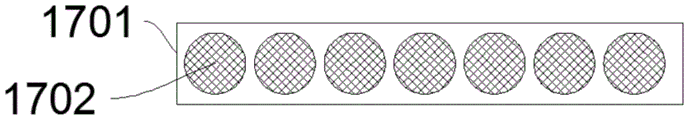
A plurality of groups of sludge discharge holes 11 are formed in the cleaning component shell 4, and the plurality of groups of sludge discharge holes 11 are positioned at the bottom of the cleaning component shell 4; a filter screen 17 is installed on the plurality of groups of sludge discharge holes 11, and the filter screen 17 is positioned at the bottom end of the interior of the cleaning component shell 4.
The filter screen 17 comprises an outer frame 1701 and filter meshes 1702, wherein the filter meshes 1702 are uniformly distributed in the central axis of the outer frame 1701, and the filter meshes 1702 correspond to the sludge discharge holes 11 one by one; a sludge discharge pipe 12 is arranged below the sludge discharge hole 11, the sludge discharge hole 11 is communicated with the sludge discharge pipe 12, and one end of the sludge discharge pipe 12 penetrates to the outer side of the cleaning assembly shell 4.
Ore enters the cleaning assembly 1 through the first feeding groove 5, the servo motor 8 drives the spiral conveying shaft 13 to rotate, and the ore rotates along with the spiral conveying shaft 13; the water pump runs through the one end of wasing the subassembly shell through water injection pipe 10, right water injection pipe 10 carries out the water injection.
9 water of apopore wash the ore, and the silt that washes down passes through filter screen 17 gets into mud discharging hole 11, filter screen 17 is a whole, is difficult for following drop on the mud discharging hole 11, passes through at last mud discharging pipe 12 flows out.
The cleaned ore is discharged from the first discharge port 6 through the rotation of the spiral conveying shaft 13, a buffer layer is arranged in the first discharge port 6, the buffer layer can be made of rubber, and the impact on the scattering assembly 2 can be reduced by the buffer layer.
The breaker assembly 2 comprises a second feed chute 18, a chain bar 20 and a second platform 22; illustratively, as shown in fig. 4 and 5, a baffle rod 19 is arranged inside the second feeding chute 18, and the baffle rod 19 has an upper layer and a lower layer;
two sides of the second feeding chute 18 are in transmission connection with a second bracket 21 through the chain rods 20; the bottom of the second bracket 21 is fixedly connected with the second platform 22; a first reciprocating motor 23 is mounted on the second platform 22, and the output end of the first reciprocating motor 23 is in transmission connection with the second feeding chute 18 through a first transmission rod 24.
Ore enters the second feeding chute 18 through the first discharging hole 6, and the first reciprocating motor is positioned at the bottom of the second bracket 21, so that the maintenance is convenient; the first reciprocating motor 23 drives the second feeding chute 18 to vibrate, and agglomerated ores are thoroughly scattered through the two groups of stop levers 19; the ore is broken up and flows into the feed inlet of the grading component 3.
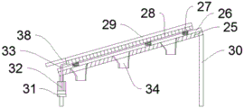
The grading component 3 comprises a grading plate 25, a sieve plate 28, a third support 30, a second discharge port 34 and a third discharge port 38, for example, as shown in fig. 7 and 8, the bottom of the grading plate 25 is fixedly connected with the third support 30, the grading plate 25 is arranged in an inclined manner, and an included angle between the central axis of the grading plate 25 and the horizontal plane is 20-25 degrees; the classifying plate 25 is provided with first baffles 26 at both sides thereof.
The screen deck 28 comprises a first screen aperture 35, a second screen aperture 36 and a third screen aperture 37; the first screen openings 35 are located at the side of the second screen openings 36 and the third screen openings 37 are located at the side of the second screen openings 36 remote from the first screen openings 35; the aperture of the sieve holes 35, 36 and 37 are increased in sequence; two sides of the sieve plate 28 are respectively fixedly connected with a second baffle plate 29;
the screen plate 28 is provided with dust collecting holes 42 arranged side by side, the screen plate 28 is internally provided with a plurality of rows of dust collecting pipes 43, the dust collecting holes 42 are respectively communicated with the dust collecting pipes 43 correspondingly, and the dust collecting pipes 43 are respectively connected to the connecting pipes 44.
The sieve plate 28 can collect the soot in the dust collecting hole 42 during the vibration, and further adsorb and convey the dust through the dust suction pipe 43, thereby further conveying and processing the dust.
The grading plate 25 is in transmission connection with the sieve plate 28 through three groups of springs 27, the three groups of springs 27 are uniformly distributed, and the grading plate 25 is parallel to the sieve plate 28; the lower end of the sieve plate 28 is fixedly connected with a third discharge hole 38.
A third platform 31 is arranged on the third support 30, the third platform 31 is located at the bottom of the third support 30, a second reciprocating motor 32 is mounted on the third platform 31, and the output end of the second reciprocating motor 32 is in transmission connection with one end of the sieve plate 28 through a second transmission rod 33.
The bottom of the classifying plate 25 is provided with three groups of second discharge holes 34, and the second discharge holes 34 are respectively positioned below the first screen holes 35, the second screen holes 36 and the third screen holes 37.
Ore flows out through the lower opening of the second feed chute 18 and enters the sieve plate 28; the second reciprocating motor 32 drives the sieve plate 28 to vibrate, and the second reciprocating motor 32 is positioned at the bottom, so that the maintenance is convenient; the two sides of the grading plate 25 are provided with first baffle plates 26, the two sides of the sieve plate 28 are fixedly connected with second baffle plates 29, and the ore on the grading plate 25 or the sieve plate 28 is blocked and limited to prevent the ore from scattering.
Ores with different sizes are classified through the first sieve holes 35, the second sieve holes 36 and the third sieve holes 37, and the ores with different sizes respectively enter the different second discharge holes 34 and flow out through the different second discharge holes 34; the remaining ore flows out through the third outlet 38.
The second discharging hole 34 comprises a second discharging hole upper part 3401 and a second discharging hole lower part 3402, as shown in fig. 9, the bottom surface of the second discharging hole upper part 3401 is hinged with the bottom surface of the second discharging hole lower part 3402, a first hanging rod 39 is arranged on one side of the second discharging hole lower part 3402 close to the second discharging hole upper part 3401, and a plurality of groups of second hanging rods 41 are arranged on one side of the second discharging hole upper part 3401 close to the second discharging hole lower part 3402; the first hanging rod 39 is connected with the second hanging rod 41 through a hook 40.
Couple 40 is hung differently when second peg 41 is gone up, can realize adjusting the direction of the lower part of second discharge gate 34, and then the outflow direction of control ore ensures that the moving direction of ore is unanimous with transfer direction of transfer apparatus, avoids the ore to scatter and causes the impact to transfer apparatus.
Ore enters the cleaning assembly 1 through the first feeding groove 5, the servo motor 8 drives the spiral conveying shaft 13 to rotate, and the ore rotates along with the spiral conveying shaft 13; the water pump penetrates through one end of the shell of the cleaning assembly through a water injection pipe 10 to inject water into the water injection pipe 10;
the water outlet hole 9 is used for cleaning ores, the filter screen 17 is used for separating ores and silt, the filter screen 17 is a whole and is not easy to fall off from the mud discharging hole 11, and the silt generated by cleaning enters the mud discharging pipe 12 through the mud discharging hole 11 and flows out;
the cleaned ore flows out of the first discharge hole 6 through the rotation of the spiral conveying shaft 13, and a buffer layer is arranged in the first discharge hole 6, so that the impact on the stop lever 19 can be reduced.
The ore passes through the upper shed of second feed chute 18 flows in break up subassembly 2, first reciprocating motor 23 drives second feed chute 18 vibrations are thoroughly broken up the ore of caking through two sets of pin 19.
Ore flows out through the lower opening of the second feed chute 18 and enters the upper end of the sieve plate 28; the second reciprocating motor 32 drives the sieve plate 28 to vibrate, and the second reciprocating motor 32 is positioned at the bottom, so that the maintenance is convenient; the two sides of the grading plate 25 are provided with first baffle plates 26, the two sides of the sieve plate 28 are fixedly connected with second baffle plates 29, and the ore on the grading plate 25 or the sieve plate 28 is limited to prevent the ore from scattering.
The ores with different sizes are classified through the first sieve holes 35, the second sieve holes 36 and the third sieve holes 37, and the ores with different sizes respectively enter the different second discharge holes 34; the unfractionated ore flows out through the third discharge port 38;
the couple 40 is hung when different on the second peg 41, can realize adjusting second discharge gate lower part 3402 direction, and then the outflow direction of control ore ensures that the moving direction of ore is unanimous with transfer direction of transfer apparatus, avoids the ore to scatter and causes the impact to transfer apparatus.
The mixing and compacting assembly comprises a compacting module 64, a discharging module 63 and a stirring and conveying module 65;
the stirring and conveying module 65 is arranged at the top of the pressing module 64, a stirring cavity 46 is arranged in the stirring and conveying module 65, a conveying pipe 50 is arranged at the bottom of the stirring and conveying module 65, a spiral stirrer 47 which rotates in the conveying pipe 50 is arranged in the stirring cavity 46, a connecting pipe 44 is arranged at one side of the stirring and conveying module 65, and a drain pipe 49 is arranged at the other side of the stirring and conveying module 65;
the compacting module 64 is internally provided with a compacting cavity 51, the conveying pipe 50 extends into the compacting cavity 51, the compacting cavity 51 is internally provided with a sliding top pressing cover 52 on the conveying pipe 50, a circle of soil conveying pipe 55 corresponding to the conveying pipe 50 is arranged on the top pressing rod 52, soil conveying holes 59 are respectively formed in the soil conveying pipe 55, the compacting module 64 is arranged on the discharging module 63, the discharging module 63 is provided with a conveying groove 56 corresponding to the compacting cavity 51, a sliding first pressing plate 57 and a sliding second pressing plate 66 are arranged in the conveying groove 56, and the connecting pipe 44 adsorbs powder generated by the grading component 3.
Can further carry the powder in stirring chamber 46 through connecting pipe 44, carry the stirring chamber 46 with water through drain pipe 49 in, and then stir coal ash, can carry the coal ash after the stirring to compress tightly the chamber 51 through the rotation of auger delivery 47 in, be provided with a gliding roof pressure lid 52 in compressing tightly chamber 51, roof pressure lid 52 slides simultaneously on conveyer pipe 50, after the coal ash after the stirring is carried and is compressed tightly the chamber 51, can compress tightly coal ash through the slip of roof pressure lid 52, and then can make the coal ash shaping, can carry contaminated earth through earth conveyer pipe 55, carry the fashioned coal ash with contaminated earth through conveyer pipe 55 in, and then can compress tightly contaminated earth in the coal cinder through the slip of roof pressure lid 52, and then can burn the earth of mud through the burning of later stage, thereby avoid the problem that mud can't be handled, the sludge treatment effect of the sludge is greatly improved, and the formed coal briquette can be further conveyed through the first pressing plate 57 and the second pressing plate 66, so that the subsequent treatment is carried out on the coal briquette.
As shown in fig. 9 to 13, the stirring and conveying module 65 is provided with an air aspirator 45, the air aspirator 45 sucks the connecting pipe 44 to generate wind power and conveys the wind power into the stirring cavity 46, the screw conveyor 47 is provided with a stirring rack 48 which rotates in the stirring cavity 46, and the top of the stirring and conveying module 65 is provided with a motor which drives the screw stirrer 47 to rotate.
Rotate through motor drive helical agitator 47, and then can drive stirring frame 48 and rotate to stir coal ash and water through stirring frame 48's rotation, can breathe in connecting pipe 44 through aspirator 45, and then can carry out concentrated collection to coal ash and handle.
As shown in fig. 9 to 13, the pressing cavity 51 and the top pressing cover 52 are respectively arranged in a circular shape, the pressing cover 52 and the pressing cavity 51 are connected in a sealing manner, 4 telescopic sliders 53 which are correspondingly and crossly arranged are arranged on the top pressing cover 52, 4 first gears 54 driven by a motor are arranged in the pressing module 64, and tooth grooves which are correspondingly engaged and connected with the first gears 54 are arranged on the telescopic sliders 53;
the soil conveying pipes 55 respectively slide on the top pressing covers 52, the top parts of the top pressing covers 52 are respectively provided with a spring pressing slide block 60, the spring pressing slide blocks 60 are respectively provided with a return spring 61, and the return springs 61 are respectively fixedly connected to the top pressing covers 52;
the discharging module 63 is provided with a first hydraulic rod 58 for controlling the first pressing plate 57 to slide, and the discharging module 63 is provided with a second hydraulic rod 67 for controlling the second pressing plate 66 to slide.
Can compress tightly coal ash after the slip through compressing tightly lid 52 to can compress tightly coal ash and be the piece, drive through clicking first gear 54 rotates telescopic sliding block 53 is last be provided with the tooth's socket that the corresponding meshing of first gear 54 is connected, and then can control top gland 52's flexible slip to compress tightly the coal cinder, can carry the earth that oil pollutes in the coal cinder that compresses tightly through earth conveyer pipe 55, thereby accomplish the transport of mud, can control simultaneously through first hydraulic stem 58 the action of first clamp plate 57, through the slip of second hydraulic stem 67 control second clamp plate 66, and then can carry the coal cinder after compressing tightly, thereby through subsequent burning, can carry the earth that oil pollutes, great improvement the treatment effeciency of mud.
Although the present invention has been described in detail with reference to the foregoing embodiments, it will be understood by those of ordinary skill in the art that: the technical solutions described in the foregoing embodiments may still be modified, or some technical features may be equivalently replaced; and such modifications or substitutions do not depart from the spirit and scope of the corresponding technical solutions of the embodiments of the present invention.