CN112468712A - Energy-saving monitoring device based on green new forms of energy - Google Patents
Energy-saving monitoring device based on green new forms of energy Download PDFInfo
- Publication number
- CN112468712A CN112468712A CN202011441621.5A CN202011441621A CN112468712A CN 112468712 A CN112468712 A CN 112468712A CN 202011441621 A CN202011441621 A CN 202011441621A CN 112468712 A CN112468712 A CN 112468712A
- Authority
- CN
- China
- Prior art keywords
- plate
- wall
- energy
- monitoring device
- device based
- Prior art date
- Legal status (The legal status is an assumption and is not a legal conclusion. Google has not performed a legal analysis and makes no representation as to the accuracy of the status listed.)
- Withdrawn
Links
- 238000012806 monitoring device Methods 0.000 title claims abstract description 24
- 230000007246 mechanism Effects 0.000 claims abstract description 40
- 230000003014 reinforcing effect Effects 0.000 claims abstract description 14
- 230000008878 coupling Effects 0.000 claims description 13
- 238000010168 coupling process Methods 0.000 claims description 13
- 238000005859 coupling reaction Methods 0.000 claims description 13
- 238000010030 laminating Methods 0.000 claims description 5
- 230000000694 effects Effects 0.000 claims description 3
- 238000009434 installation Methods 0.000 abstract description 7
- 238000013461 design Methods 0.000 abstract description 3
- 238000012544 monitoring process Methods 0.000 description 7
- 230000002349 favourable effect Effects 0.000 description 4
- 238000004519 manufacturing process Methods 0.000 description 3
- 239000000463 material Substances 0.000 description 3
- 238000004891 communication Methods 0.000 description 2
- 238000005516 engineering process Methods 0.000 description 2
- 230000001771 impaired effect Effects 0.000 description 2
- 238000012423 maintenance Methods 0.000 description 2
- 238000000926 separation method Methods 0.000 description 2
- 230000004075 alteration Effects 0.000 description 1
- 230000009286 beneficial effect Effects 0.000 description 1
- 230000008901 benefit Effects 0.000 description 1
- 230000008859 change Effects 0.000 description 1
- 238000010276 construction Methods 0.000 description 1
- 230000007613 environmental effect Effects 0.000 description 1
- 230000003993 interaction Effects 0.000 description 1
- 238000000034 method Methods 0.000 description 1
- 238000012986 modification Methods 0.000 description 1
- 230000004048 modification Effects 0.000 description 1
- 238000006467 substitution reaction Methods 0.000 description 1
- 230000033772 system development Effects 0.000 description 1
Images



Classifications
-
- H—ELECTRICITY
- H04—ELECTRIC COMMUNICATION TECHNIQUE
- H04N—PICTORIAL COMMUNICATION, e.g. TELEVISION
- H04N23/00—Cameras or camera modules comprising electronic image sensors; Control thereof
- H04N23/50—Constructional details
- H04N23/51—Housings
-
- F—MECHANICAL ENGINEERING; LIGHTING; HEATING; WEAPONS; BLASTING
- F16—ENGINEERING ELEMENTS AND UNITS; GENERAL MEASURES FOR PRODUCING AND MAINTAINING EFFECTIVE FUNCTIONING OF MACHINES OR INSTALLATIONS; THERMAL INSULATION IN GENERAL
- F16M—FRAMES, CASINGS OR BEDS OF ENGINES, MACHINES OR APPARATUS, NOT SPECIFIC TO ENGINES, MACHINES OR APPARATUS PROVIDED FOR ELSEWHERE; STANDS; SUPPORTS
- F16M11/00—Stands or trestles as supports for apparatus or articles placed thereon ; Stands for scientific apparatus such as gravitational force meters
- F16M11/02—Heads
- F16M11/04—Means for attachment of apparatus; Means allowing adjustment of the apparatus relatively to the stand
-
- H—ELECTRICITY
- H02—GENERATION; CONVERSION OR DISTRIBUTION OF ELECTRIC POWER
- H02S—GENERATION OF ELECTRIC POWER BY CONVERSION OF INFRARED RADIATION, VISIBLE LIGHT OR ULTRAVIOLET LIGHT, e.g. USING PHOTOVOLTAIC [PV] MODULES
- H02S20/00—Supporting structures for PV modules
- H02S20/30—Supporting structures being movable or adjustable, e.g. for angle adjustment
-
- Y—GENERAL TAGGING OF NEW TECHNOLOGICAL DEVELOPMENTS; GENERAL TAGGING OF CROSS-SECTIONAL TECHNOLOGIES SPANNING OVER SEVERAL SECTIONS OF THE IPC; TECHNICAL SUBJECTS COVERED BY FORMER USPC CROSS-REFERENCE ART COLLECTIONS [XRACs] AND DIGESTS
- Y02—TECHNOLOGIES OR APPLICATIONS FOR MITIGATION OR ADAPTATION AGAINST CLIMATE CHANGE
- Y02E—REDUCTION OF GREENHOUSE GAS [GHG] EMISSIONS, RELATED TO ENERGY GENERATION, TRANSMISSION OR DISTRIBUTION
- Y02E10/00—Energy generation through renewable energy sources
- Y02E10/50—Photovoltaic [PV] energy
Landscapes
- Engineering & Computer Science (AREA)
- General Engineering & Computer Science (AREA)
- Multimedia (AREA)
- Signal Processing (AREA)
- Mechanical Engineering (AREA)
- Photovoltaic Devices (AREA)
Abstract
The invention discloses an energy-saving monitoring device based on green new energy, which comprises an installation seat, a vertical plate, a reinforcing plate and a storage plate, wherein the vertical plate is fixedly connected to the right side of the installation seat, the reinforcing plate is fixedly connected to the left side of the vertical plate, the upper surface of the reinforcing plate is fixedly connected with the installation seat, the right side of the storage plate is movably connected with the top end of the vertical plate, and a fixing mechanism is arranged inside the storage plate. This energy-saving monitoring device based on green new forms of energy, through the frid, the connecting rod, the cooperation of extension spring and splint etc. is used, the frid is moved to the right in the left side of putting the thing board, the position through changing splint makes things convenient for not unidimensional solar panel's fixed, increase application range, through the horizontal pole, the sheave, the cooperation of shell and screw cap etc. is used, the convenient receipts hank to the wire of design like this, through the threaded rod, the carousel, the slider, the swash plate, the cooperation of second bolt and second nut etc. is used, can adjust solar panel's inclination.
Description
Technical Field
The invention relates to the technical field of energy-saving monitoring devices, in particular to an energy-saving monitoring device based on green new energy.
Background
The monitoring system is one of the most applied systems in the security system, the construction site monitoring system suitable for the market is a handheld video communication device, video monitoring is the mainstream at present, and the change of the coverage of the ground is caused from the earliest analog monitoring to the digital monitoring in the past years to the current rise of the network video monitoring. Today in the IP technique global of progressively unifying, we are necessary to know video monitoring system development history again, need to use solar panel for supervisory equipment provides the electric energy along with the enhancement of environmental protection theory, but current energy-saving monitoring device based on green new forms of energy, inconvenient fixing not unidimensional solar panel, the practicality that leads to whole mechanism descends, the wire of connecting the camera is comparatively mixed and disorderly for a long time, inconvenient regulation to solar panel inclination, hardly satisfy in the production life the user demand to energy-saving monitoring device.
Disclosure of Invention
The invention aims to provide an energy-saving monitoring device based on green new energy, and the energy-saving monitoring device is used for solving the problem that the practicability of the whole mechanism is reduced due to the fact that the existing energy-saving monitoring device based on green new energy is inconvenient to fix solar panels with different sizes in the background technology.
In order to achieve the purpose, the invention provides the following technical scheme: an energy-saving monitoring device based on green new energy comprises an installation seat, a vertical plate, a reinforcing plate and an object placing plate, wherein the vertical plate is fixedly connected to the right side of the installation seat, the reinforcing plate is fixedly connected to the left side of the vertical plate, the upper surface of the reinforcing plate is fixedly connected with the installation seat, the object placing plate is installed at the top end of the vertical plate, the right side of the object placing plate is movably connected with the top end of the vertical plate, and a fixing mechanism is installed inside the object placing plate;
the fixing mechanism comprises a groove plate, a connecting rod, an extension spring and a clamping plate;
the outer wall of frid and putting the thing board clearance fit, the bottom rigid coupling of frid has the connecting rod, the right side rigid coupling of connecting rod has extension spring, extension spring's right side and putting thing board rigid coupling, the top rigid coupling of frid has splint.
Preferably, the trough plate and the storage plate form a sliding mechanism.
Preferably, the upper surface of putting the thing board is laminated with solar panel, solar panel's the left and right sides laminate mutually with splint and thing board respectively, the connecting plate is installed to the bottom of mount pad, first bolt has been cup jointed to the inside of connecting plate, the outer wall of first bolt runs through mount pad and connecting plate and first nut threaded connection, the outer wall and the equal clearance fit of mount pad and connecting plate of first bolt, the outer wall and the mount pad of first nut laminate mutually, the lower surface laminating of connecting plate has the camera.
Preferably, the right side of the vertical plate is provided with a take-up mechanism;
the take-up mechanism comprises a cross rod, a grooved wheel, a shell and a threaded cap;
the left side of horizontal pole and the right side looks rigid coupling of riser, the outer wall of horizontal pole has cup jointed the sheave, the inner wall and the horizontal pole interference fit of sheave, the outer wall clearance fit of sheave has the shell, the inner wall and the horizontal pole clearance fit of shell, the right side screw thread of horizontal pole is equipped with the screw cap, the inner wall of screw cap and the outer wall threaded connection of horizontal pole, the left side of screw cap closely laminates with the right side of shell.
Preferably, the cross bar is arranged perpendicular to the sheave.
Preferably, an adjusting mechanism is installed inside the installation seat;
the adjusting mechanism comprises a threaded rod, a rotary table, a sliding block, an inclined plate, a second bolt and a second nut;
the outer wall of threaded rod passes through the inside activity of bearing and mount pad and links to each other, the carousel has been cup jointed in the left side of threaded rod, the inside and the threaded rod interference fit of carousel, the outer wall threaded connection of threaded rod has the slider, the outer wall of slider and the inside spout clearance fit of mount pad, the top of slider is equipped with the swash plate, the top of swash plate with put thing board activity and link to each other, the second bolt has been cup jointed to the inside of swash plate, the outer wall of second bolt runs through swash plate and slider and second nut threaded connection, the outer wall of second bolt and the equal clearance fit of slider and swash plate, the outer wall and the swash plate of second nut laminate mutually.
Preferably, the bottom of the camera is provided with a connecting mechanism;
the connecting mechanism comprises a gasket, an arc-shaped rod and a third nut;
the upper surface and the camera of gasket are laminated mutually, the outer wall laminating of gasket has the arc pole, two the top of arc pole all runs through connecting plate and third nut threaded connection, the outer wall and the connecting plate clearance fit of arc pole.
Compared with the prior art, the invention has the beneficial effects that: this energy-saving monitoring device based on green new forms of energy compares traditional technology, has following advantage:
the solar panel storage rack is characterized in that the groove plate is moved rightwards on the left side of the storage plate through the matching of the groove plate, the connecting rod, the extension spring, the clamping plate and the like, the groove plate drives the extension spring to deform through the connecting rod, the solar panel is placed on the upper surface of the storage plate, the elastic force of the extension spring is used for fixing the solar panel, the position of the clamping plate is changed to enable the solar panel to be fixed in different sizes, the use range is enlarged, and the practicability of the whole mechanism is further improved.
The cooperation through horizontal pole, sheave, shell and screw cap etc. is used, twines the wire of camera at the outer wall of sheave, and the top of wire links to each other with solar panel, covers the shell at the outer wall of sheave afterwards, uses the screw cap to carry out the rigidity to the shell, and convenient in design is favorable to using widely to the receipts hank of wire like this.
Through the cooperation use of threaded rod, carousel, slider, swash plate, second bolt and second nut etc, rotate the carousel and drive the threaded rod and rotate in the mount pad, the threaded rod rotates and drives the slider removal, will put the swash plate of thing board lower surface and place on the top of slider, use second bolt and second nut to fix slider and swash plate, can adjust solar panel's inclination, be favorable to solar panel to absorb sunshine.
Through the cooperation use of gasket, arc pole and third nut etc., rotate third nut and arc pole separation, dismantle arc pole and backing plate and get off the back and maintain the camera, the backing plate makes for rubber materials prevents that the camera is impaired, and the convenience is to the maintenance of camera, satisfies the user demand to energy-conserving monitoring device in the production life greatly.
Drawings
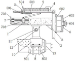
FIG. 1 is a schematic structural view of the present invention;
FIG. 2 is a schematic view of a connection structure between the fixing mechanism and the object placing plate in FIG. 1;
FIG. 3 is a schematic view of the connection structure of the take-up mechanism and the vertical plate in FIG. 1;
FIG. 4 is a schematic view of a connection structure between the adjusting mechanism and the mounting base in FIG. 1;
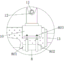
FIG. 5 is a schematic view of a connection structure between the connection mechanism and the camera in FIG. 1;
fig. 6 is a schematic view of a connection structure of the connection between the sliding block, the inclined plate and the storage plate in fig. 1.
In the figure: 1. the solar panel comprises a mounting seat, 2, a vertical plate, 3, a reinforcing plate, 4, a storage plate, 5, a fixing mechanism, 501, a groove plate, 502, a connecting rod, 503, an extension spring, 504, a clamping plate, 6, a take-up mechanism, 601, a cross rod, 602, a grooved wheel, 603, a shell, 604, a thread cap, 7, an adjusting mechanism, 701, a threaded rod, 702, a rotary disc, 703, a sliding block, 704, an inclined plate, 705, a second bolt, 706, a second nut, 8, a connecting mechanism, 801, a gasket, 802, an arc-shaped rod, 803, a third nut, 9, a solar panel, 10, a connecting plate, 11, a first bolt, 12, a first nut, 13 and a camera.
Detailed Description
The technical solutions in the embodiments of the present invention will be clearly and completely described below with reference to the drawings in the embodiments of the present invention, and it is obvious that the described embodiments are only a part of the embodiments of the present invention, and not all of the embodiments. All other embodiments, which can be derived by a person skilled in the art from the embodiments given herein without making any creative effort, shall fall within the protection scope of the present invention.
Referring to fig. 1-6, the present invention provides a technical solution: an energy-saving monitoring device based on green new energy comprises a mounting seat 1, a vertical plate 2, a reinforcing plate 3 and an object placing plate 4, wherein the vertical plate 2 is fixedly connected to the right side of the mounting seat 1, the reinforcing plate 3 is fixedly connected to the left side of the vertical plate 2, the upper surface of the reinforcing plate 3 is fixedly connected with the mounting seat 1, the reinforcing plate 3 increases the connection strength between the vertical plate 2 and the mounting seat 1, the object placing plate 4 is installed at the top end of the vertical plate 2, the right side of the object placing plate 4 is movably connected with the top end of the vertical plate 2, the object placing plate 4 is movably connected with the vertical plate 2 through a pin shaft, a fixing mechanism 5 is installed inside the object placing plate 4, the fixing mechanism 5 comprises a groove plate 501, a connecting rod 502, a tension spring 503 and a clamping plate 504, the outer wall of the groove plate 501 is in clearance fit with the object placing plate 4, a bump is processed on the outer wall of the groove plate 501, the connecting rod 502 is fixedly, the right side of the extension spring 503 is fixedly connected with the object placing plate 4, the top end of the groove plate 501 is fixedly connected with the clamping plate 504, the groove plate 501 and the object placing plate 4 form a sliding mechanism, and the groove plate 501 can move in the object placing plate 4;
the solar panel storage rack is characterized in that the groove plate is moved rightwards on the left side of the storage plate through the matching of the groove plate, the connecting rod, the extension spring, the clamping plate and the like, the groove plate drives the extension spring to deform through the connecting rod, the solar panel is placed on the upper surface of the storage plate, the elastic force of the extension spring is used for fixing the solar panel, the position of the clamping plate is changed to enable the solar panel to be fixed in different sizes, the use range is enlarged, and the practicability of the whole mechanism is further improved.
Put the upper surface of thing board 4 and laminate solar panel 9, solar panel 9's the left and right sides respectively with splint 504 with put thing board 4 and laminate mutually, connecting plate 10 is installed to mount pad 1's bottom, frid 504 carries out the rigidity to solar panel 9, first bolt 11 has been cup jointed to the inside of connecting plate 10, mount pad 1 and connecting plate 10 and first nut 12 threaded connection are run through to the outer wall of first bolt 11, the outer wall of first bolt 11 and mount pad 1 and the equal clearance fit of connecting plate 10, connecting plate 10 can be adjusted in mount pad 1, use first bolt 11 and first nut 12 to fix between connecting plate 10 and the mount pad 1, the outer wall of first nut 12 laminates mutually with mount pad 1, the lower surface laminating of connecting plate 10 has camera 13, camera 13 plays about the control.
The take-up mechanism 6 is installed on the right side of the vertical plate 2, the take-up mechanism 6 comprises a cross rod 601, a grooved pulley 602, a shell 603 and a threaded cap 604, the left side of the cross rod 601 is fixedly connected with the right side of the vertical plate 2, the grooved pulley 602 is sleeved on the outer wall of the cross rod 601, the inner wall of the grooved pulley 602 is in interference fit with the cross rod 601, a stranded wire can be taken up and stranded by the grooved pulley 602, the shell 603 is in clearance fit with the outer wall of the grooved pulley 602, the inner wall of the shell 603 is in clearance fit with the cross rod 601, through grooves are machined on the upper side and the lower side of the shell 603, the threaded cap 604 is arranged on the right side of the cross rod 601, the inner wall of the threaded cap 604 is in threaded connection with the outer wall of;
the cooperation through horizontal pole, sheave, shell and screw cap etc. is used, twines the wire of camera at the outer wall of sheave, and the top of wire links to each other with solar panel, covers the shell at the outer wall of sheave afterwards, uses the screw cap to carry out the rigidity to the shell, and convenient in design is favorable to using widely to the receipts hank of wire like this.
An adjusting mechanism 7 is arranged inside the mounting seat 1, the adjusting mechanism 7 comprises a threaded rod 701, a rotary plate 702, a sliding block 703, an inclined plate 704, a second bolt 705 and a second nut 706, the outer wall of the threaded rod 701 is movably connected with the inside of the mounting seat 1 through a bearing, the rotary plate 702 drives the threaded rod 701 to rotate, the rotary plate 702 is sleeved on the left side of the threaded rod 701, the inside of the rotary plate 702 is in interference fit with the threaded rod 701, the sliding block 703 is connected with the outer wall of the threaded rod 701 through threads, the outer wall of the sliding block 703 is in clearance fit with an inner sliding groove of the mounting seat 1, the inclined plate 704 is arranged at the top end of the sliding block 703, the top end of the inclined plate 704 is movably connected with the object placing plate 4, the inclined plate 704 is movably connected with the object placing plate 4 through a pin shaft, the second bolt is sleeved inside the inclined plate 704, the outer wall of the second bolt 705 penetrates, the outer wall of the second nut 706 is attached to the sloping plate 704, and the second bolt 705 and the second nut 706 connect the sliding block 703 and the sloping plate 704;
through the cooperation use of threaded rod, carousel, slider, swash plate, second bolt and second nut etc, rotate the carousel and drive the threaded rod and rotate in the mount pad, the threaded rod rotates and drives the slider removal, will put the swash plate of thing board lower surface and place on the top of slider, use second bolt and second nut to fix slider and swash plate, can adjust solar panel's inclination, be favorable to solar panel to absorb sunshine.
The bottom of the camera 13 is provided with a connecting mechanism 8, the connecting mechanism 8 comprises a gasket 801, arc-shaped rods 802 and a third nut 803, the upper surface of the gasket 801 is attached to the camera 13, the gasket 801 is made of rubber materials, the arc-shaped rods 802 are attached to the outer wall of the gasket 801, the top ends of the two arc-shaped rods 802 penetrate through the connecting plate 10 and are in threaded connection with the third nut 803, the outer wall of the arc-shaped rods 802 is in clearance fit with the connecting plate 10, and the third nut 803 fixes the positions of the arc-shaped rods 802;
through the cooperation use of gasket, arc pole and third nut etc., rotate third nut and arc pole separation, dismantle arc pole and backing plate and get off the back and maintain the camera, the backing plate makes for rubber materials prevents that the camera is impaired, and the convenience is to the maintenance of camera, satisfies the user demand to energy-conserving monitoring device in the production life greatly.
In this example, when the monitoring device is used, firstly, the slot plate 501 is moved rightwards on the left side of the object placing plate 4, the slot plate 501 drives the extension spring 503 to deform through the connecting rod 502, the solar panel 9 is placed on the upper surface of the object placing plate 4, the solar panel 9 is fixed by the elasticity of the extension spring 503, the conducting wire of the camera 13 is wound on the outer wall of the grooved wheel 602, the top end of the conducting wire is connected with the solar panel 9, then the outer shell 603 is covered on the outer wall of the grooved wheel 602, the position of the outer shell 603 is fixed by the threaded cap 604, when the solar panel 9 needs to be adjusted in angle, the threaded rod 701 is driven to rotate in the mounting seat 1 by rotating the rotary disc 702, the sliding block 703 is driven to move by the rotation of the threaded rod 701, the inclined plate 704 on the lower surface of the object placing plate 4 is placed on the top end of the sliding block, the sliding block 703 and the inclined plate, the camera 13 is maintained after the arc-shaped rod 802 and the backing plate 801 are detached.
In the description of the present invention, it is to be understood that the terms "coaxial", "bottom", "one end", "top", "middle", "other end", "upper", "one side", "top", "inner", "front", "center", "both ends", and the like, indicate orientations or positional relationships based on those shown in the drawings, and are only for convenience of description and simplicity of description, and do not indicate or imply that the referenced device or element must have a particular orientation, be constructed and operated in a particular orientation, and thus, are not to be construed as limiting the present invention.
In the present invention, unless otherwise expressly specified or limited, the terms "mounted," "disposed," "connected," "secured," "screwed" and the like are to be construed broadly, e.g., as meaning fixedly connected, detachably connected, or integrally formed; can be mechanically or electrically connected; the terms may be directly connected or indirectly connected through an intermediate, and may be communication between two elements or interaction relationship between two elements, unless otherwise specifically limited, and the specific meaning of the terms in the present invention will be understood by those skilled in the art according to specific situations.
Although embodiments of the present invention have been shown and described, it will be appreciated by those skilled in the art that changes, modifications, substitutions and alterations can be made in these embodiments without departing from the principles and spirit of the invention, the scope of which is defined in the appended claims and their equivalents.
Claims (7)
1. The utility model provides an energy-saving monitoring device based on green new forms of energy, includes mount pad (1), riser (2), reinforcing plate (3) and puts thing board (4), the right side rigid coupling of mount pad (1) has riser (2), the left side rigid coupling of riser (2) has reinforcing plate (3), the upper surface and mount pad (1) looks rigid coupling of reinforcing plate (3), the top of riser (2) is installed and is put thing board (4), the right side of putting thing board (4) links to each other its characterized in that with the top activity of riser (2): a fixing mechanism (5) is arranged in the object placing plate (4); the fixing mechanism (5) comprises a groove plate (501), a connecting rod (502), an extension spring (503) and a clamping plate (504); the outer wall of frid (501) with put thing board (4) clearance fit, the bottom rigid coupling of frid (501) has connecting rod (502), the right side rigid coupling of connecting rod (502) has extension spring (503), the right side of extension spring (503) with put thing board (4) looks rigid coupling, the top rigid coupling of frid (501) has splint (504).
2. The energy-saving monitoring device based on green new energy according to claim 1, characterized in that: the groove plate (501) and the object placing plate (4) form a sliding mechanism.
3. The energy-saving monitoring device based on green new energy according to claim 1, characterized in that: the upper surface of putting thing board (4) is laminated with solar panel (9), the left and right sides of solar panel (9) laminate with splint (504) and putting thing board (4) respectively mutually, connecting plate (10) are installed to the bottom of mount pad (1), first bolt (11) have been cup jointed to the inside of connecting plate (10), the outer wall of first bolt (11) runs through mount pad (1) and connecting plate (10) and first nut (12) threaded connection, the outer wall of first bolt (11) and mount pad (1) and the equal clearance fit of connecting plate (10), the outer wall of first nut (12) laminates with mount pad (1) mutually, the lower surface laminating of connecting plate (10) has camera (13).
4. The energy-saving monitoring device based on green new energy according to claim 1, characterized in that: a take-up mechanism (6) is arranged on the right side of the vertical plate (2); the take-up mechanism (6) comprises a cross rod (601), a grooved wheel (602), a shell (603) and a threaded cap (604); the left side of horizontal pole (601) and the right side looks rigid coupling of riser (2), the outer wall of horizontal pole (601) has cup jointed sheave (602), the inner wall and horizontal pole (601) interference fit of sheave (602), the outer wall clearance fit of sheave (602) has shell (603), the inner wall and horizontal pole (601) clearance fit of shell (603), the right side screw thread of horizontal pole (601) is equipped with screw cap (604), the inner wall of screw cap (604) and the outer wall threaded connection of horizontal pole (601), the left side of screw cap (604) closely laminates with the right side of shell (603).
5. The energy-saving monitoring device based on green new energy according to claim 4, characterized in that: the cross rod (601) is perpendicular to the grooved wheel (602).
6. The energy-saving monitoring device based on green new energy according to claim 1, characterized in that: an adjusting mechanism (7) is arranged in the mounting seat (1); the adjusting mechanism (7) comprises a threaded rod (701), a rotary disc (702), a sliding block (703), a sloping plate (704), a second bolt (705) and a second nut (706); the outer wall of the threaded rod (701) is movably connected with the inside of the mounting seat (1) through a bearing, the left side of the threaded rod (701) is sleeved with a rotary table (702), the inner part of the rotary table (702) is in interference fit with the threaded rod (701), the outer wall of the threaded rod (701) is in threaded connection with a sliding block (703), the outer wall of the sliding block (703) is in clearance fit with an inner sliding groove of the mounting seat (1), the top end of the sliding block (703) is provided with an inclined plate (704), the top end of the inclined plate (704) is movably connected with the object placing plate (4), a second bolt (705) is sleeved in the inclined plate (704), the outer wall of the second bolt (705) penetrates through the inclined plate (704) and the sliding block (703) to be in threaded connection with a second nut (706), the outer wall of the second bolt (705) is in clearance fit with the sliding block (703) and the sloping plate (704), and the outer wall of the second nut (706) is attached to the sloping plate (704).
7. The energy-saving monitoring device based on green new energy according to claim 3, characterized in that: the bottom of the camera (13) is provided with a connecting mechanism (8); the connecting mechanism (8) comprises a gasket (801), an arc-shaped rod (802) and a third nut (803); the upper surface and the camera (13) of gasket (801) are laminated mutually, the outer wall laminating of gasket (801) has arc pole (802), two the top of arc pole (802) all runs through connecting plate (10) and third nut (803) threaded connection, the outer wall and connecting plate (10) clearance fit of arc pole (802).
Priority Applications (1)
| Application Number | Priority Date | Filing Date | Title |
|---|---|---|---|
| CN202011441621.5A CN112468712A (en) | 2020-12-11 | 2020-12-11 | Energy-saving monitoring device based on green new forms of energy |
Applications Claiming Priority (1)
| Application Number | Priority Date | Filing Date | Title |
|---|---|---|---|
| CN202011441621.5A CN112468712A (en) | 2020-12-11 | 2020-12-11 | Energy-saving monitoring device based on green new forms of energy |
Publications (1)
| Publication Number | Publication Date |
|---|---|
| CN112468712A true CN112468712A (en) | 2021-03-09 |
Family
ID=74801280
Family Applications (1)
| Application Number | Title | Priority Date | Filing Date |
|---|---|---|---|
| CN202011441621.5A Withdrawn CN112468712A (en) | 2020-12-11 | 2020-12-11 | Energy-saving monitoring device based on green new forms of energy |
Country Status (1)
| Country | Link |
|---|---|
| CN (1) | CN112468712A (en) |
Cited By (1)
| Publication number | Priority date | Publication date | Assignee | Title |
|---|---|---|---|---|
| CN113623510A (en) * | 2021-05-25 | 2021-11-09 | 国盾(山东)知识产权运营管理有限公司 | Scientific and technological management innovation projection explanation appearance convenient to adjust |
-
2020
- 2020-12-11 CN CN202011441621.5A patent/CN112468712A/en not_active Withdrawn
Cited By (1)
| Publication number | Priority date | Publication date | Assignee | Title |
|---|---|---|---|---|
| CN113623510A (en) * | 2021-05-25 | 2021-11-09 | 国盾(山东)知识产权运营管理有限公司 | Scientific and technological management innovation projection explanation appearance convenient to adjust |
Similar Documents
| Publication | Publication Date | Title |
|---|---|---|
| CN209134341U (en) | A kind of balcony photovoltaic bracket | |
| CN112468712A (en) | Energy-saving monitoring device based on green new forms of energy | |
| CN215335390U (en) | Monitoring device for emergency disposal area | |
| CN212752465U (en) | Multi-angle rotating no-dead-angle video monitoring equipment | |
| CN212131801U (en) | Suspension type LED double screen | |
| CN210089793U (en) | Water level monitoring device for aquaculture | |
| CN210968610U (en) | Anchor clamps are used in photovoltaic glass production | |
| CN208982919U (en) | The good monitoring bar of a kind of easy for installation and stability | |
| CN215981840U (en) | Adjustable installation mechanism for gun type monitoring camera | |
| CN216012326U (en) | Suspension lifting type local environment detection device | |
| CN215069530U (en) | Anti-electric-shock transformer rack | |
| CN216079101U (en) | Water conservancy automation information acquisition device convenient to maintain | |
| CN212366694U (en) | Zinc-nickel alloy electroplating cable bridge | |
| CN112565583B (en) | Network dead-angle-free monitoring device based on big data | |
| CN210168119U (en) | Security protection supervisory equipment convenient to loading and unloading | |
| CN212287128U (en) | Polishing device for production of missile wing framework | |
| CN210950688U (en) | Monitoring camera is with adjustable base | |
| CN112318925A (en) | Hydraulic press slider locking device and hydraulic press | |
| CN216217139U (en) | Turn to controllable security protection video monitoring equipment | |
| CN221276819U (en) | Split type building steel construction of easy installation | |
| CN205142357U (en) | Safe surveillance camera head | |
| CN210168361U (en) | Communication power supply module capable of being installed quickly | |
| CN220647348U (en) | Intelligent security monitoring device for building | |
| CN212402946U (en) | Power line tension device for power line paying-off | |
| CN211858549U (en) | Circuit breaker parallel arrangement structure |
Legal Events
| Date | Code | Title | Description |
|---|---|---|---|
| PB01 | Publication | ||
| PB01 | Publication | ||
| SE01 | Entry into force of request for substantive examination | ||
| SE01 | Entry into force of request for substantive examination | ||
| WW01 | Invention patent application withdrawn after publication |
Application publication date: 20210309 |
|
| WW01 | Invention patent application withdrawn after publication |