CN112461663A - Optical fiber cable tensile deformation detection device - Google Patents
Optical fiber cable tensile deformation detection device Download PDFInfo
- Publication number
- CN112461663A CN112461663A CN202011351132.0A CN202011351132A CN112461663A CN 112461663 A CN112461663 A CN 112461663A CN 202011351132 A CN202011351132 A CN 202011351132A CN 112461663 A CN112461663 A CN 112461663A
- Authority
- CN
- China
- Prior art keywords
- fixedly connected
- optical fiber
- tensile deformation
- fiber cable
- screws
- Prior art date
- Legal status (The legal status is an assumption and is not a legal conclusion. Google has not performed a legal analysis and makes no representation as to the accuracy of the status listed.)
- Granted
Links
- 239000013307 optical fiber Substances 0.000 title claims abstract description 30
- 238000001514 detection method Methods 0.000 title claims abstract description 13
- 239000000835 fiber Substances 0.000 claims description 10
- 238000009434 installation Methods 0.000 claims description 6
- 239000000463 material Substances 0.000 claims description 2
- 230000003287 optical effect Effects 0.000 description 15
- 238000000034 method Methods 0.000 description 5
- 239000004033 plastic Substances 0.000 description 3
- 238000005096 rolling process Methods 0.000 description 3
- NIXOWILDQLNWCW-UHFFFAOYSA-N acrylic acid group Chemical group C(C=C)(=O)O NIXOWILDQLNWCW-UHFFFAOYSA-N 0.000 description 2
- 230000005540 biological transmission Effects 0.000 description 2
- 238000004891 communication Methods 0.000 description 2
- 230000008878 coupling Effects 0.000 description 2
- 238000010168 coupling process Methods 0.000 description 2
- 238000005859 coupling reaction Methods 0.000 description 2
- 239000011521 glass Substances 0.000 description 2
- 229910052751 metal Inorganic materials 0.000 description 2
- 239000002184 metal Substances 0.000 description 2
- 230000001681 protective effect Effects 0.000 description 2
- 230000000007 visual effect Effects 0.000 description 2
- RYGMFSIKBFXOCR-UHFFFAOYSA-N Copper Chemical compound [Cu] RYGMFSIKBFXOCR-UHFFFAOYSA-N 0.000 description 1
- 229910001294 Reinforcing steel Inorganic materials 0.000 description 1
- BQCADISMDOOEFD-UHFFFAOYSA-N Silver Chemical compound [Ag] BQCADISMDOOEFD-UHFFFAOYSA-N 0.000 description 1
- 229910052782 aluminium Inorganic materials 0.000 description 1
- XAGFODPZIPBFFR-UHFFFAOYSA-N aluminium Chemical compound [Al] XAGFODPZIPBFFR-UHFFFAOYSA-N 0.000 description 1
- 230000009286 beneficial effect Effects 0.000 description 1
- 238000005253 cladding Methods 0.000 description 1
- 239000002131 composite material Substances 0.000 description 1
- 229910052802 copper Inorganic materials 0.000 description 1
- 239000010949 copper Substances 0.000 description 1
- 230000000694 effects Effects 0.000 description 1
- 238000005516 engineering process Methods 0.000 description 1
- 230000007613 environmental effect Effects 0.000 description 1
- 239000000945 filler Substances 0.000 description 1
- PCHJSUWPFVWCPO-UHFFFAOYSA-N gold Chemical compound [Au] PCHJSUWPFVWCPO-UHFFFAOYSA-N 0.000 description 1
- 229910052737 gold Inorganic materials 0.000 description 1
- 239000010931 gold Substances 0.000 description 1
- 150000002739 metals Chemical class 0.000 description 1
- 238000012986 modification Methods 0.000 description 1
- 230000004048 modification Effects 0.000 description 1
- 238000012946 outsourcing Methods 0.000 description 1
- 230000000149 penetrating effect Effects 0.000 description 1
- 230000008054 signal transmission Effects 0.000 description 1
- 229910052709 silver Inorganic materials 0.000 description 1
- 239000004332 silver Substances 0.000 description 1
- 238000012360 testing method Methods 0.000 description 1
Images


Classifications
-
- G—PHYSICS
- G01—MEASURING; TESTING
- G01N—INVESTIGATING OR ANALYSING MATERIALS BY DETERMINING THEIR CHEMICAL OR PHYSICAL PROPERTIES
- G01N3/00—Investigating strength properties of solid materials by application of mechanical stress
- G01N3/08—Investigating strength properties of solid materials by application of mechanical stress by applying steady tensile or compressive forces
-
- G—PHYSICS
- G01—MEASURING; TESTING
- G01N—INVESTIGATING OR ANALYSING MATERIALS BY DETERMINING THEIR CHEMICAL OR PHYSICAL PROPERTIES
- G01N3/00—Investigating strength properties of solid materials by application of mechanical stress
- G01N3/02—Details
-
- G—PHYSICS
- G01—MEASURING; TESTING
- G01N—INVESTIGATING OR ANALYSING MATERIALS BY DETERMINING THEIR CHEMICAL OR PHYSICAL PROPERTIES
- G01N2203/00—Investigating strength properties of solid materials by application of mechanical stress
- G01N2203/0001—Type of application of the stress
- G01N2203/0003—Steady
-
- G—PHYSICS
- G01—MEASURING; TESTING
- G01N—INVESTIGATING OR ANALYSING MATERIALS BY DETERMINING THEIR CHEMICAL OR PHYSICAL PROPERTIES
- G01N2203/00—Investigating strength properties of solid materials by application of mechanical stress
- G01N2203/0014—Type of force applied
- G01N2203/0016—Tensile or compressive
- G01N2203/0017—Tensile
-
- G—PHYSICS
- G01—MEASURING; TESTING
- G01N—INVESTIGATING OR ANALYSING MATERIALS BY DETERMINING THEIR CHEMICAL OR PHYSICAL PROPERTIES
- G01N2203/00—Investigating strength properties of solid materials by application of mechanical stress
- G01N2203/003—Generation of the force
- G01N2203/005—Electromagnetic means
-
- G—PHYSICS
- G01—MEASURING; TESTING
- G01N—INVESTIGATING OR ANALYSING MATERIALS BY DETERMINING THEIR CHEMICAL OR PHYSICAL PROPERTIES
- G01N2203/00—Investigating strength properties of solid materials by application of mechanical stress
- G01N2203/0058—Kind of property studied
- G01N2203/0069—Fatigue, creep, strain-stress relations or elastic constants
- G01N2203/0075—Strain-stress relations or elastic constants
-
- G—PHYSICS
- G01—MEASURING; TESTING
- G01N—INVESTIGATING OR ANALYSING MATERIALS BY DETERMINING THEIR CHEMICAL OR PHYSICAL PROPERTIES
- G01N2203/00—Investigating strength properties of solid materials by application of mechanical stress
- G01N2203/02—Details not specific for a particular testing method
- G01N2203/026—Specifications of the specimen
- G01N2203/0262—Shape of the specimen
- G01N2203/0278—Thin specimens
- G01N2203/028—One dimensional, e.g. filaments, wires, ropes or cables
-
- G—PHYSICS
- G01—MEASURING; TESTING
- G01N—INVESTIGATING OR ANALYSING MATERIALS BY DETERMINING THEIR CHEMICAL OR PHYSICAL PROPERTIES
- G01N2203/00—Investigating strength properties of solid materials by application of mechanical stress
- G01N2203/02—Details not specific for a particular testing method
- G01N2203/06—Indicating or recording means; Sensing means
- G01N2203/0641—Indicating or recording means; Sensing means using optical, X-ray, ultraviolet, infrared or similar detectors
-
- G—PHYSICS
- G01—MEASURING; TESTING
- G01N—INVESTIGATING OR ANALYSING MATERIALS BY DETERMINING THEIR CHEMICAL OR PHYSICAL PROPERTIES
- G01N2203/00—Investigating strength properties of solid materials by application of mechanical stress
- G01N2203/02—Details not specific for a particular testing method
- G01N2203/06—Indicating or recording means; Sensing means
- G01N2203/067—Parameter measured for estimating the property
- G01N2203/0682—Spatial dimension, e.g. length, area, angle
-
- Y—GENERAL TAGGING OF NEW TECHNOLOGICAL DEVELOPMENTS; GENERAL TAGGING OF CROSS-SECTIONAL TECHNOLOGIES SPANNING OVER SEVERAL SECTIONS OF THE IPC; TECHNICAL SUBJECTS COVERED BY FORMER USPC CROSS-REFERENCE ART COLLECTIONS [XRACs] AND DIGESTS
- Y02—TECHNOLOGIES OR APPLICATIONS FOR MITIGATION OR ADAPTATION AGAINST CLIMATE CHANGE
- Y02P—CLIMATE CHANGE MITIGATION TECHNOLOGIES IN THE PRODUCTION OR PROCESSING OF GOODS
- Y02P70/00—Climate change mitigation technologies in the production process for final industrial or consumer products
- Y02P70/10—Greenhouse gas [GHG] capture, material saving, heat recovery or other energy efficient measures, e.g. motor control, characterised by manufacturing processes, e.g. for rolling metal or metal working
Landscapes
- Physics & Mathematics (AREA)
- Health & Medical Sciences (AREA)
- Life Sciences & Earth Sciences (AREA)
- Chemical & Material Sciences (AREA)
- Analytical Chemistry (AREA)
- Biochemistry (AREA)
- General Health & Medical Sciences (AREA)
- General Physics & Mathematics (AREA)
- Immunology (AREA)
- Pathology (AREA)
- Investigating Strength Of Materials By Application Of Mechanical Stress (AREA)
- Length Measuring Devices By Optical Means (AREA)
Abstract
The invention discloses a device for detecting the tensile deformation of an optical fiber cable, which belongs to the technical field of detection devices and comprises a shell, a top column, a bottom column, a composition plate and a side box, wherein the top of an inner cavity of the shell and the bottom of the inner cavity are fixedly connected with the top column and the bottom column through screws, the bottom of the top column is fixedly connected with a top column mounting seat through screws, and the bottom of the top column mounting seat is fixedly connected with a fixed frame, the purpose of detecting the tensile deformation of the optical fiber cable is achieved.
Description
Technical Field
The invention relates to the technical field of detection devices, in particular to a device for detecting tensile deformation of an optical fiber cable.
Background
Optical fiber is a shorthand for optical fiber, a fiber made of glass or plastic that can be used as a light conducting means, while fiber optic cables are manufactured to meet optical, mechanical or environmental performance specifications, which utilize one or more optical fibers disposed in a covering jacket as the transmission medium and can be used individually or in groups as a communications cable assembly. The optical cable is mainly composed of optical fibers (thin glass filaments like hair), a plastic protective sleeve and a plastic sheath, and metals such as gold, silver, copper and aluminum are not contained in the optical cable.
The optical cable is that the cable core is constituteed according to certain mode to a certain quantity of optic fibre, and the outsourcing has the sheath, and some still cladding outer sheaths for realize optical signal transmission's a communication line, promptly: the basic structure of an optical cable, which is formed by an optical fiber (optical transmission carrier) through a certain process, generally consists of a cable core, a reinforcing steel wire, a filler, a sheath and the like, and further comprises a waterproof layer, a buffer layer, an insulated metal wire and other components according to requirements.
Before the optical fiber cable is used, in order to detect the deformed supportable strength, the optical fiber cable is optionally required to be matched with a detection device for testing and detecting the optical fiber cable.
The existing optical cable is mainly applied to one end fixing force in the process of stretching deformation, the optical cable is lack of an effective matching limiting mode, the optical cable is enabled to swing in the stress process, the stability of detection is affected, data acquisition errors are large, the main stress area cannot be observed, and the visual effect is poor.
Disclosure of Invention
The invention aims to provide an optical fiber cable tensile deformation detection device, which aims to solve the problems that the existing optical cable provided in the background technology mainly applies force by fixing one end and applying force by fixing the other end, and the optical cable lacks an effective matching limit mode, so that the optical cable swings in the stress process, the detection stability is influenced, the data acquisition error is large, the main stress area cannot be observed, and the visual effect is poor.
In order to achieve the purpose, the invention provides the following technical scheme: a device for detecting tensile deformation of an optical fiber cable comprises a shell, a top column, a bottom column, a combined plate and a side box, wherein the top of an inner cavity and the bottom of the inner cavity of the shell are fixedly connected with the top column and the bottom column through screws, the bottom of the top column is fixedly connected with a top column mounting seat through screws, the bottom of the top column mounting seat is fixedly connected with a fixing frame, the side wall of the shell is fixedly connected with the side box through screws, the bottom of the fixing frame is fixedly connected with a lantern ring, a fastening ring is sleeved on the circumferential inner wall of the lantern ring, the bottom of the top column mounting seat is movably connected with a movable frame through a pin shaft, the bottom of the movable frame is fixedly connected with the combined plate through screws, the side wall of the combined plate is fixedly connected with a guide device through screws, a guide plate is bonded on the rear side wall of the guide device, a main arc plate and, the top and the bottom of guide board are through screw fixedly connected with main guide frame and vice guide frame, the lantern ring with optic fibre has been cup jointed to guide board inside, main guide frame with the slide has all been bonded at the both ends of vice guide frame, the slide with spout sliding connection, screw fixedly connected with variable frequency controller and driving motor are passed through to the inner chamber bottom of side case, variable frequency controller's electrical output end electric connection driving motor, variable frequency controller's electrical input end electric connection has the signal frame, the electrical input end electric connection of signal frame has the camera, driving motor's output has the roller of rolling through the coupling joint, the circumference outer wall that rolls the roller cup joints optic fibre.
Preferably, the preceding lateral wall of shell has the protecting cover through hinge swing joint, the recess has been seted up to the preceding lateral wall of protecting cover, the inside of recess is inlayed and is had the observation window.
Preferably, the installation position of the bottom column and the installation position of the top column are on the same horizontal line.
Preferably, the bottom shapes of the main arc plate and the auxiliary arc plate are both arc-shaped, and the main arc plate and the auxiliary arc plate are made of rubber plates.
Preferably, the front side wall of the side box is movably connected with a side box cover through a hinge.
Preferably, the front side wall of the combination plate is fixedly connected with a combination seat through a screw, and the movable frame is fixedly connected with the combination seat.
Preferably, the material of observation window is transparent acrylic sheet.
Preferably, the top and the bottom of the roller are in threaded connection with limiting plates.
Compared with the prior art, the invention has the beneficial effects that: this kind of optical fiber cable tensile deformation detection device, through the combination application of accessory, but the opposite fore-set and the bottom prop that set up of shell internal combination to utilize the lantern ring on the mount to fix optic fibre, the adjustable shelf that carries the compoboard pulls optic fibre with the help of the guide board, driving motor in the cooperation side case is opened the roller, optic fibre rolling process can cooperate and carry out tensile deformation, and cooperate the camera to observe the main stress area of optic fibre, reach the purpose that optical fiber cable tensile deformation detected.
Drawings
FIG. 1 is a schematic view of the overall structure of the present invention;
FIG. 2 is a schematic view of the interior of the structure of the present invention;
FIG. 3 is a schematic view of the back of the composite board of the present invention;
FIG. 4 is a schematic view of the internal structure of the side box of the present invention.
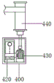
In the figure: 100 casing, 110 protecting cover, 120 observation window, 200 top column, 210 top column mounting seat, 220 fixed frame, 230 lantern ring, 240 movable frame, 250 bottom column, 300 combined plate, 310 combined seat, 320 guider, 330 guide plate, 331 main arc plate, 332 auxiliary arc plate, 340 main guide frame, 350 auxiliary guide frame, 400 side box, 410 side box cover, 420 variable frequency controller, 421 camera, 422 signal frame, 430 driving motor, 440 roller.
Detailed Description
The technical solutions in the embodiments of the present invention will be clearly and completely described below with reference to the drawings in the embodiments of the present invention, and it is obvious that the described embodiments are only a part of the embodiments of the present invention, and not all of the embodiments. All other embodiments, which can be derived by a person skilled in the art from the embodiments given herein without making any creative effort, shall fall within the protection scope of the present invention.
The invention provides a device for detecting the tensile deformation of an optical fiber cable, which is convenient for the tensile detection of the optical fiber cable through the combined application of accessories, has strong detection stability, is convenient for observing a stressed area, and refers to fig. 1, fig. 2, fig. 3 and fig. 4, and comprises a shell 100, a top column 200, a bottom column 250, a combined plate 300 and a side box 400;
referring to fig. 1 again, the front side wall of the housing 100 has a protecting cover 110, specifically, the front side wall of the housing 100 is movably connected to the protecting cover 110 through a hinge, the front side wall of the protecting cover 110 is provided with a groove, and an observation window 120 is embedded in the groove;
referring to fig. 1 and 2 again, the top of the top pillar 200 is connected to the housing 100, specifically, the top and bottom of the inner cavity of the housing 100 are fixedly connected to the top pillar 200 and the bottom pillar 250 through screws, the bottom of the top pillar 200 is fixedly connected to the top pillar mounting base 210 through screws, the bottom of the top pillar mounting base 210 is fixedly connected to the fixed frame 220, the bottom of the fixed frame 220 is fixedly connected to the lantern ring 230, the inner wall of the circumference of the lantern ring 230 is sleeved with the fastening ring, and the bottom of the top pillar mounting base 210 is movably connected to the movable frame 240 through a pin shaft;
referring to fig. 2 and 3 again, the combination plate 300 is combined with the movable frame 240, specifically, the bottom of the movable frame 240 is fixedly connected with the combination plate 300 through screws, the side wall of the combination plate 300 is fixedly connected with the guide 320 through screws, the rear side wall of the guide 320 is bonded with the guide plate 330, the rear side wall of the guide plate 330 is bonded with the main arc plate 331 and the auxiliary arc plate 332, the top and the bottom of the guide plate 330 are fixedly connected with the main guide frame 340 and the auxiliary guide frame 350 through screws, the lantern ring 230 and the guide plate 330 are sleeved with optical fibers, and both ends of the main guide frame 340 and the auxiliary guide frame 350 are bonded with sliding plates which are connected with sliding grooves in a sliding manner;
referring to fig. 1 and 4 again, the side box 400 is combined with the housing 100, specifically, the side wall of the housing 100 is fixedly connected to the side box 400 through screws, the bottom of the inner cavity of the side box 400 is fixedly connected to the variable frequency controller 420 and the driving motor 430 through screws, the electrical output end of the variable frequency controller 420 is electrically connected to the driving motor 430, the electrical input end of the variable frequency controller 420 is electrically connected to the signal frame 422, the electrical input end of the signal frame 422 is electrically connected to the camera 421, the output end of the driving motor 430 is connected to the roller 440 through a coupling, and the circumferential outer wall of the roller 440 is sleeved with an optical fiber;
when the cable guide device is used specifically, firstly, the protective cover 110 is combined in front of the shell 100, the top column 200 and the bottom column 250 are combined in the shell 100, the top column 200 and the bottom column are connected with the fixed frame 220 and the movable frame 240 through the top column mounting seat 210, the fixed frame 220 and the movable frame 240 are matched with the bottom column 250 for fixing, the cable structure is fixed by penetrating the lantern ring 230, the cable is fixed by matching with the guide plate 330 outside the cable, the guide plate 330 is provided with the main arc plate 331 and the auxiliary arc plate 332 for increasing the guide effect on the cable, the main guide frame 340 and the auxiliary guide frame 350 are combined at the two ends of the guide 320 and can slide at the two ends of the inner cavity of the shell 100 for matching with the sliding process in the limit, after the variable frequency controller 420 controls the driving motor 430 to use, the rolling roller 440 can rotate, the cable is forced in the rotation, the signal frame 422 carrying the camera 421 is arranged on the main force bearing area of the cable, the detection picture in the deformation of the, is convenient for observation.
Referring to fig. 2 again, in order to ensure that the bottom pillar 250 and the top pillar 200 can interact with each other and ensure stability during use, specifically, the installation position of the bottom pillar 250 and the installation position of the top pillar 200 are on the same horizontal line.
Referring to fig. 3 again, in order to clamp the optical cable, specifically, the bottom portions of the main arc plate 331 and the auxiliary arc plate 332 are both arc-shaped, and the main arc plate 331 and the auxiliary arc plate 332 are made of rubber plates.
Referring to fig. 1 again, in order to shield the internal environment of the side box 400, specifically, the front side wall of the side box 400 is movably connected to a side box cover 410 by a hinge.
Referring to fig. 2 and 3 again, in order to facilitate the stability of the connection with the combination board 300, specifically, the combination board 300 is fixedly connected to the combination base 310 through a screw on the front side wall, and the movable frame 240 is fixedly connected to the combination base 310.
Referring to fig. 1 again, in order to observe the internal environment of the housing 100 after the cover 110 is fixed, the observation window 120 is made of a transparent acrylic plate.
Referring to fig. 4 again, in order to reduce the possibility of the optical cable being detached during the rotation of the roller 440, specifically, the top and bottom of the roller 440 are threadedly connected with a limiting plate.
While the invention has been described above with reference to an embodiment, various modifications may be made and equivalents may be substituted for elements thereof without departing from the scope of the invention. In particular, the various features of the embodiments disclosed herein may be used in any combination, provided that there is no structural conflict, and the combinations are not exhaustively described in this specification merely for the sake of brevity and conservation of resources. Therefore, it is intended that the invention not be limited to the particular embodiments disclosed, but that the invention will include all embodiments falling within the scope of the appended claims.
Claims (8)
1. The utility model provides a tensile deformation detection device of fiber optic cable which characterized in that: the combined type wall post comprises a shell (100), a top post (200), a bottom post (250), a combined plate (300) and a side box (400), wherein the top of an inner cavity of the shell (100) is fixedly connected with the top post (200) and the bottom of the inner cavity of the bottom post (250) through screws, the bottom of the top post (200) is fixedly connected with a top post mounting seat (210) through screws, the bottom of the top post mounting seat (210) is fixedly connected with a fixed frame (220), the side wall of the shell (100) is fixedly connected with the side box (400) through screws, the bottom of the fixed frame (220) is fixedly connected with a lantern ring (230), the inner wall of the circumference of the lantern ring (230) is sleeved with a fastening ring, the bottom of the top post mounting seat (210) is movably connected with a movable frame (240) through a pin shaft, the bottom of the movable frame (240) is fixedly connected with the combined plate (300) through screws, and the side wall of the combined, the rear side wall of the guider (320) is bonded with a guide plate (330), the rear side wall of the guide plate (330) is bonded with a main arc plate (331) and an auxiliary arc plate (332), the top and the bottom of the guide plate (330) are fixedly connected with a main guide frame (340) and an auxiliary guide frame (350) through screws, the lantern ring (230) and the guide plate (330) are internally sleeved with optical fibers, sliding plates are respectively bonded at the two ends of the main guide frame (340) and the auxiliary guide frame (350), the sliding plates are in sliding connection with the sliding grooves, the bottom of the inner cavity of the side box (400) is fixedly connected with a variable frequency controller (420) and a driving motor (430) through screws, the electrical output end of the variable frequency controller (420) is electrically connected with the driving motor (430), the electrical input end of the variable frequency controller (420) is electrically connected with a signal frame (422), the electrical input end of the signal frame (422) is electrically connected with a camera (421), the output end of the driving motor (430) is connected with a roller (440) through a coupler, and the outer wall of the circumference of the roller (440) is sleeved with the optical fiber.
2. The optical fiber cable tensile deformation detecting device according to claim 1, wherein: the utility model discloses a portable electronic device, including shell (100), preceding lateral wall has protecting cover (110) through hinge swing joint, the recess has been seted up to the preceding lateral wall of protecting cover (110), the inside of recess is inlayed and is had observation window (120).
3. The optical fiber cable tensile deformation detecting device according to claim 2, wherein: the installation position of the bottom column (250) and the installation position of the top column (200) are on the same horizontal line.
4. The optical fiber cable tensile deformation detecting device according to claim 3, wherein: the bottom shapes of the main arc plate (331) and the auxiliary arc plate (332) are both arc-shaped, and the main arc plate (331) and the auxiliary arc plate (332) are made of rubber plates.
5. The optical fiber cable tensile deformation detecting device according to claim 4, wherein: the front side wall of the side box (400) is movably connected with a side box cover (410) through a hinge.
6. The optical fiber cable tensile deformation detecting device according to claim 5, wherein: the front side wall of the combined plate (300) is fixedly connected with a combined seat (310) through screws, and the movable frame (240) is fixedly connected with the combined seat (310).
7. The optical fiber cable tensile deformation detecting device according to claim 6, wherein: the material of observation window (120) is transparent ya keli board.
8. The optical fiber cable tensile deformation detecting device according to claim 7, wherein: the top and the bottom of the roller (440) are in threaded connection with limiting plates.
Priority Applications (1)
| Application Number | Priority Date | Filing Date | Title |
|---|---|---|---|
| CN202011351132.0A CN112461663B (en) | 2020-11-27 | 2020-11-27 | Optical fiber cable tensile deformation detection device |
Applications Claiming Priority (1)
| Application Number | Priority Date | Filing Date | Title |
|---|---|---|---|
| CN202011351132.0A CN112461663B (en) | 2020-11-27 | 2020-11-27 | Optical fiber cable tensile deformation detection device |
Publications (2)
| Publication Number | Publication Date |
|---|---|
| CN112461663A true CN112461663A (en) | 2021-03-09 |
| CN112461663B CN112461663B (en) | 2022-11-11 |
Family
ID=74809661
Family Applications (1)
| Application Number | Title | Priority Date | Filing Date |
|---|---|---|---|
| CN202011351132.0A Active CN112461663B (en) | 2020-11-27 | 2020-11-27 | Optical fiber cable tensile deformation detection device |
Country Status (1)
| Country | Link |
|---|---|
| CN (1) | CN112461663B (en) |
Cited By (2)
| Publication number | Priority date | Publication date | Assignee | Title |
|---|---|---|---|---|
| CN117310868A (en) * | 2023-09-26 | 2023-12-29 | 浙江贝良风能电子科技有限公司 | Fiber grating stretching equipment and method of using the same |
| CN118602899A (en) * | 2024-07-31 | 2024-09-06 | 南通同裕光电科技有限公司 | A device for detecting tensile deformation of optical fiber and optical cable |
Citations (14)
| Publication number | Priority date | Publication date | Assignee | Title |
|---|---|---|---|---|
| JPH05215656A (en) * | 1992-01-31 | 1993-08-24 | Furukawa Electric Co Ltd:The | Method for testing tensile strength of fiber connecting section |
| JPH07167643A (en) * | 1993-12-14 | 1995-07-04 | Reideitsuku:Kk | Slope collapse detector |
| KR20020061355A (en) * | 2001-01-16 | 2002-07-24 | 박봉수 | tention measurement device for optical cable |
| US20050002622A1 (en) * | 2001-11-19 | 2005-01-06 | Ralph Sutehall | Optical fibre drop cables |
| JP2009068162A (en) * | 1995-03-11 | 2009-04-02 | Truetzschler Gmbh & Co Kg | Method and apparatus for severing sliver during can replacement in drawing frame |
| CN206126472U (en) * | 2016-08-31 | 2017-04-26 | 云南开放大学 | Cable pulling device |
| CN206244183U (en) * | 2016-12-10 | 2017-06-13 | 南京鑫瀚瑞电子有限公司 | cable winder |
| CN207300739U (en) * | 2017-09-26 | 2018-05-01 | 李红旗 | A kind of testing device for super multi-core cable of super speed flat type elevator |
| CN208171778U (en) * | 2018-05-18 | 2018-11-30 | 无锡智泉科技有限公司 | Steel rope abrasion degree detection device |
| CN209148423U (en) * | 2018-12-11 | 2019-07-23 | 乐山师范学院 | A tensile device for strength testing of basalt fiber composites |
| CN210108859U (en) * | 2019-06-14 | 2020-02-21 | 山东鲁信通光电科技有限公司 | OPGW optical cable tension testing device |
| CN110962327A (en) * | 2019-11-14 | 2020-04-07 | 绍兴日月新材料有限公司 | High performance polyester film's drawing equipment |
| CN211110449U (en) * | 2019-11-04 | 2020-07-28 | 江苏鑫博高分子材料有限公司 | Spinning stretching and winding device for high-molecular elastic fibers |
| CN211555599U (en) * | 2019-11-27 | 2020-09-22 | 江苏金枫达电缆有限公司 | Cable fire-resistant mica tape wrapping device |
-
2020
- 2020-11-27 CN CN202011351132.0A patent/CN112461663B/en active Active
Patent Citations (14)
| Publication number | Priority date | Publication date | Assignee | Title |
|---|---|---|---|---|
| JPH05215656A (en) * | 1992-01-31 | 1993-08-24 | Furukawa Electric Co Ltd:The | Method for testing tensile strength of fiber connecting section |
| JPH07167643A (en) * | 1993-12-14 | 1995-07-04 | Reideitsuku:Kk | Slope collapse detector |
| JP2009068162A (en) * | 1995-03-11 | 2009-04-02 | Truetzschler Gmbh & Co Kg | Method and apparatus for severing sliver during can replacement in drawing frame |
| KR20020061355A (en) * | 2001-01-16 | 2002-07-24 | 박봉수 | tention measurement device for optical cable |
| US20050002622A1 (en) * | 2001-11-19 | 2005-01-06 | Ralph Sutehall | Optical fibre drop cables |
| CN206126472U (en) * | 2016-08-31 | 2017-04-26 | 云南开放大学 | Cable pulling device |
| CN206244183U (en) * | 2016-12-10 | 2017-06-13 | 南京鑫瀚瑞电子有限公司 | cable winder |
| CN207300739U (en) * | 2017-09-26 | 2018-05-01 | 李红旗 | A kind of testing device for super multi-core cable of super speed flat type elevator |
| CN208171778U (en) * | 2018-05-18 | 2018-11-30 | 无锡智泉科技有限公司 | Steel rope abrasion degree detection device |
| CN209148423U (en) * | 2018-12-11 | 2019-07-23 | 乐山师范学院 | A tensile device for strength testing of basalt fiber composites |
| CN210108859U (en) * | 2019-06-14 | 2020-02-21 | 山东鲁信通光电科技有限公司 | OPGW optical cable tension testing device |
| CN211110449U (en) * | 2019-11-04 | 2020-07-28 | 江苏鑫博高分子材料有限公司 | Spinning stretching and winding device for high-molecular elastic fibers |
| CN110962327A (en) * | 2019-11-14 | 2020-04-07 | 绍兴日月新材料有限公司 | High performance polyester film's drawing equipment |
| CN211555599U (en) * | 2019-11-27 | 2020-09-22 | 江苏金枫达电缆有限公司 | Cable fire-resistant mica tape wrapping device |
Cited By (2)
| Publication number | Priority date | Publication date | Assignee | Title |
|---|---|---|---|---|
| CN117310868A (en) * | 2023-09-26 | 2023-12-29 | 浙江贝良风能电子科技有限公司 | Fiber grating stretching equipment and method of using the same |
| CN118602899A (en) * | 2024-07-31 | 2024-09-06 | 南通同裕光电科技有限公司 | A device for detecting tensile deformation of optical fiber and optical cable |
Also Published As
| Publication number | Publication date |
|---|---|
| CN112461663B (en) | 2022-11-11 |
Similar Documents
| Publication | Publication Date | Title |
|---|---|---|
| CN112461663B (en) | Optical fiber cable tensile deformation detection device | |
| CA2084501A1 (en) | Video Logging System Having Remote Power Source | |
| CN102707402B (en) | Universal FTTH (fiber to the home) leading-in optical fiber cable connection protector | |
| CN210534401U (en) | A fixed protective device for optical cable | |
| CN205374813U (en) | Melt end type skin cable fiber connector | |
| CN211086704U (en) | Optical cable structure convenient to connect | |
| CN215219254U (en) | Optical transceiver module with joint protection structure | |
| CN219122474U (en) | Armored multimode single-core pigtail for communication transmission equipment | |
| CN212905601U (en) | Improved optical cable | |
| CN210924065U (en) | Indoor multi-core optical cable with groove for entering home | |
| CN212341526U (en) | Low-loss bidirectional optical fiber jumper joint for data transmission | |
| CN215833673U (en) | Optical cable auxiliary installation mechanism | |
| CN217467294U (en) | Optical cable supporting device for building 5G base station | |
| CN223389944U (en) | Optical fiber wiring groove mounting tool | |
| CN220855254U (en) | Multi-core large-core-diameter illumination optical cable connector | |
| CN213336543U (en) | Tunnel optical cable optical fiber temperature measuring device | |
| CN110456469B (en) | Optical cable breakage simulation component for optical cable production | |
| CN222689952U (en) | Optical fiber protection assembly | |
| CN213425230U (en) | Communication optical cable joint connector | |
| CN214502347U (en) | Overhead line detection device in power transformation engineering | |
| CN211878271U (en) | Laying device for computer network multimode optical cable | |
| CN206906635U (en) | A kind of optical cable docking facilities | |
| CN212083750U (en) | Novel optical cable clamp | |
| CN220339849U (en) | Tension machine with adjustable anti-interference superfine coaxial cable detects with atress interval | |
| CN219163072U (en) | Photoelectric hybrid cable |
Legal Events
| Date | Code | Title | Description |
|---|---|---|---|
| PB01 | Publication | ||
| PB01 | Publication | ||
| SE01 | Entry into force of request for substantive examination | ||
| SE01 | Entry into force of request for substantive examination | ||
| GR01 | Patent grant | ||
| GR01 | Patent grant |