CN112454093A - Piston rod surface grinding device - Google Patents
Piston rod surface grinding device Download PDFInfo
- Publication number
- CN112454093A CN112454093A CN201910864830.1A CN201910864830A CN112454093A CN 112454093 A CN112454093 A CN 112454093A CN 201910864830 A CN201910864830 A CN 201910864830A CN 112454093 A CN112454093 A CN 112454093A
- Authority
- CN
- China
- Prior art keywords
- piston rod
- wall
- grinding device
- surface grinding
- support frame
- Prior art date
- Legal status (The legal status is an assumption and is not a legal conclusion. Google has not performed a legal analysis and makes no representation as to the accuracy of the status listed.)
- Pending
Links
Images

Classifications
-
- B—PERFORMING OPERATIONS; TRANSPORTING
- B24—GRINDING; POLISHING
- B24B—MACHINES, DEVICES, OR PROCESSES FOR GRINDING OR POLISHING; DRESSING OR CONDITIONING OF ABRADING SURFACES; FEEDING OF GRINDING, POLISHING, OR LAPPING AGENTS
- B24B21/00—Machines or devices using grinding or polishing belts; Accessories therefor
- B24B21/002—Machines or devices using grinding or polishing belts; Accessories therefor for grinding edges or bevels
-
- B—PERFORMING OPERATIONS; TRANSPORTING
- B24—GRINDING; POLISHING
- B24B—MACHINES, DEVICES, OR PROCESSES FOR GRINDING OR POLISHING; DRESSING OR CONDITIONING OF ABRADING SURFACES; FEEDING OF GRINDING, POLISHING, OR LAPPING AGENTS
- B24B21/00—Machines or devices using grinding or polishing belts; Accessories therefor
- B24B21/008—Machines comprising two or more tools or having several working posts
-
- B—PERFORMING OPERATIONS; TRANSPORTING
- B24—GRINDING; POLISHING
- B24B—MACHINES, DEVICES, OR PROCESSES FOR GRINDING OR POLISHING; DRESSING OR CONDITIONING OF ABRADING SURFACES; FEEDING OF GRINDING, POLISHING, OR LAPPING AGENTS
- B24B21/00—Machines or devices using grinding or polishing belts; Accessories therefor
- B24B21/18—Accessories
-
- B—PERFORMING OPERATIONS; TRANSPORTING
- B24—GRINDING; POLISHING
- B24B—MACHINES, DEVICES, OR PROCESSES FOR GRINDING OR POLISHING; DRESSING OR CONDITIONING OF ABRADING SURFACES; FEEDING OF GRINDING, POLISHING, OR LAPPING AGENTS
- B24B27/00—Other grinding machines or devices
- B24B27/0007—Movable machines
-
- B—PERFORMING OPERATIONS; TRANSPORTING
- B24—GRINDING; POLISHING
- B24B—MACHINES, DEVICES, OR PROCESSES FOR GRINDING OR POLISHING; DRESSING OR CONDITIONING OF ABRADING SURFACES; FEEDING OF GRINDING, POLISHING, OR LAPPING AGENTS
- B24B27/00—Other grinding machines or devices
- B24B27/0023—Other grinding machines or devices grinding machines with a plurality of working posts
-
- B—PERFORMING OPERATIONS; TRANSPORTING
- B24—GRINDING; POLISHING
- B24B—MACHINES, DEVICES, OR PROCESSES FOR GRINDING OR POLISHING; DRESSING OR CONDITIONING OF ABRADING SURFACES; FEEDING OF GRINDING, POLISHING, OR LAPPING AGENTS
- B24B41/00—Component parts such as frames, beds, carriages, headstocks
- B24B41/06—Work supports, e.g. adjustable steadies
-
- B—PERFORMING OPERATIONS; TRANSPORTING
- B24—GRINDING; POLISHING
- B24B—MACHINES, DEVICES, OR PROCESSES FOR GRINDING OR POLISHING; DRESSING OR CONDITIONING OF ABRADING SURFACES; FEEDING OF GRINDING, POLISHING, OR LAPPING AGENTS
- B24B47/00—Drives or gearings; Equipment therefor
- B24B47/22—Equipment for exact control of the position of the grinding tool or work at the start of the grinding operation
Landscapes
- Engineering & Computer Science (AREA)
- Mechanical Engineering (AREA)
- Finish Polishing, Edge Sharpening, And Grinding By Specific Grinding Devices (AREA)
Abstract
The invention discloses a piston rod surface polishing device which comprises a support frame with a U-shaped structure, wherein the inner walls of two sides of the support frame are connected with support tubes through bearings, the two support tubes are connected with a support plate, the top of each support plate is provided with an installation groove along the length direction of the support plate, the inner wall of the installation groove is connected with a connecting rod in a sliding manner, fixed clamping pieces which are distributed equidistantly and are positioned right above the installation groove are welded at the top of each support plate, movable clamping pieces which are distributed equidistantly are welded at the top of each connecting rod, one end of each connecting rod is connected with a screw rod through a bearing, and one end of. According to the invention, the piston rod can be clamped by rotating the handle clockwise, the piston rod can be taken down by rotating the handle anticlockwise, two ends of the piston rod can be polished, the piston rod can be aligned conveniently, the piston rod does not need to be placed again, the time is saved, and the polishing efficiency is improved.
Description
Technical Field
The invention relates to the technical field of polishing devices, in particular to a piston rod surface polishing device.
Background
The piston rod is a connecting component for supporting the piston to do work, most of the piston rod is applied to an oil cylinder and an air cylinder movement executing component, and the piston rod is a movement component with frequent movement and high technical requirements. The piston rod passes through the metal pole cutting and then processes, the phenomenon of burr like this big or little unsmooth, unevenness will appear in two cross-sections of the metal pole that is cut down, can produce great influence to production processing afterwards, and the workman also can receive the injury easily when handling these metal pipes that are cut, daily work has been influenced, cause work efficiency's reduction, how solve this problem, certainly carry out the process of polishing to the metal pipe cross-section, at present, the instrument of polishing usually is the manual work of polishing or manual small-size polisher carries out the polishing to the metal pipe one by one, use this polisher not only needs professional polisher, professional polisher is not only few, salary is also higher, and is inefficient.
Disclosure of Invention
The invention aims to solve the defects in the prior art and provides a piston rod surface grinding device.
In order to achieve the purpose, the invention adopts the following technical scheme:
the utility model provides a piston rod surface grinding device, includes the support frame of U-shaped structure, support frame both sides inner wall all is connected with the stay tube through the bearing, and two stay tubes are connected with a backup pad, the mounting groove has been seted up along its length direction at backup pad top, and sliding connection has the connecting rod on the inner wall of mounting groove, the welding of backup pad top has the equidistance to distribute and is located the fixed clamping piece directly over the mounting groove, the welding of top of connecting rod has the removal clamping piece that the equidistance distributes, and the one end of connecting rod is connected with the screw rod through the bearing, and the one end of screw rod is connected with the handle that is located the support frame outside, sliding mounting has the push pedal on the.
Preferably, the fixed clamping piece and the movable clamping piece are both arc-shaped structures, and a clamping groove is formed between the fixed clamping piece and the movable clamping piece.
Preferably, the abrasive belt grinding machine comprises a mounting frame, a driven roller and a driving roller, wherein the driving motor is fixed on the inner wall of one end of the mounting frame, the driven roller is fixed on the inner wall of the other end of the mounting frame through a bearing, the output shaft of the driving motor is sleeved with the driving roller, the driving roller and the driven roller are sleeved with a transmission belt pulley located on the outer side of the mounting frame, and an abrasive paper tape is bonded on the outer wall of the transmission belt.
Preferably, the inner walls of the two sides of the support frame are both provided with sliding grooves along the width direction, and the two ends of the push plate are both welded with sliding blocks which are connected with the sliding grooves in a sliding mode.
Preferably, the mounting grooves which are distributed equidistantly and are of semi-cylindrical structures are formed in the top and the bottom of the outer wall of one side, close to the movable clamping piece, of the push plate, and the positions and the number of the mounting grooves are matched with those of the fixed clamping pieces.
Preferably, the one end that the backup pad is close to the screw rod offers the through-hole with the mounting groove intercommunication, and the aperture of through-hole is greater than the diameter of screw rod, set up threaded hole on the support frame is close to one side inner wall of screw rod, and screw rod and the mutual spiro union of threaded hole.
The invention has the beneficial effects that:
1. the connecting rod can slide in the mounting groove by driving the screw rod to rotate through the handle, when the handle rotates clockwise, the connecting rod drives the movable clamping piece to approach the fixed clamping piece, the movable clamping piece and the fixed clamping piece can clamp a piston rod to be polished in the clamping groove, the handle rotates anticlockwise, the connecting rod drives the movable clamping piece to be far away from the fixed clamping piece, and the piston rod is convenient to take down;
2. through the piston rod overlap joint of placing in the centre gripping inslot in the mounting groove at push pedal top, can be with pushing towards the abrasive band polisher of piston rod parallel and level through the push pedal, clockwise rotation handle fixed piston rod this moment, start the one end that the piston rod can be polished to the abrasive band polisher, the one end of piston rod is polished and is accomplished the back, close the abrasive band polisher, outside pull push pedal, the piston rod breaks away from the mounting groove at push pedal top, rotate backup pad 180 this moment, and push the push pedal to the piston rod, the piston rod overlaps with the mounting groove of push pedal bottom each other, start the other end that the piston rod can be polished to the abrasive band polisher this moment, can polish the both ends of piston rod, conveniently make the piston rod align, and.
Drawings
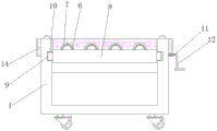
Fig. 1 is a schematic top view of a piston rod surface grinding device according to the present invention;
fig. 2 is a schematic side view of a piston rod surface grinding device according to the present invention.
In the figure: the sanding machine comprises a support frame 1, a support tube 2, a support plate 3, a mounting groove 4, a connecting rod 5, a fixed clamping piece 6, a movable clamping piece 7, a push plate 8, a sliding groove 9, a sliding block 10, a screw rod 11, a handle 12, a mounting groove 13 and an abrasive belt sander 14.
Detailed Description
The technical solutions in the embodiments of the present invention will be clearly and completely described below with reference to the drawings in the embodiments of the present invention, and it is obvious that the described embodiments are only a part of the embodiments of the present invention, and not all of the embodiments.
Referring to fig. 1-2, a piston rod surface polishing device comprises a support frame 1 with a U-shaped structure, wherein inner walls of two sides of the support frame 1 are connected with support tubes 2 through bearings, two support tubes 2 are connected with a support plate 3, the top of the support plate 3 is provided with a mounting groove 4 along the length direction, the inner wall of the mounting groove 4 is connected with a connecting rod 5 in a sliding manner, the top of the support plate 3 is welded with fixed clamping pieces 6 which are distributed equidistantly and are positioned right above the mounting groove 4, the top of the connecting rod 5 is welded with movable clamping pieces 7 which are distributed equidistantly, the fixed clamping pieces 6 and the movable clamping pieces 7 are both in an arc structure, a clamping groove is formed between the fixed clamping pieces 6 and the movable clamping pieces 7, one end of the connecting rod 5 is connected with a screw rod 11 through a bearing, one end of the support, the inner wall of one side of the support frame 1, which is close to the screw rod 11, is provided with a threaded hole, the screw rod 11 is in threaded connection with the threaded hole, one end of the screw rod 11 is connected with a handle 12 positioned at the outer side of the support frame 1, the inner walls of two sides of the support frame 1 are provided with push plates 8 in a sliding manner, the inner walls of two sides of the support frame 1 are provided with sliding grooves 9 along the width direction, two ends of each push plate 8 are welded with sliding blocks 10 in sliding connection with the inner wall of the corresponding sliding groove 9, the top and the bottom of the outer wall of one side, which is close to the movable clamping piece 7, of the push plate 8 are provided with mounting grooves 13 which are distributed equidistantly and are of a semi-columnar structure, the positions and the number of the mounting grooves 13 are matched with those of the fixed clamping pieces 6, one side, which is far away from, and the output shaft of the driving motor is sleeved with a driving roller, the driving roller and the driven roller are sleeved with a transmission belt pulley positioned outside the mounting frame, and the outer wall of the transmission belt is bonded with a sand paper tape.
The working principle is as follows: the piston rod that will place in the centre gripping inslot laps in the mounting groove 13 at push pedal 8 top, can push the abrasive band polisher 14 through push pedal 8 with the piston rod parallel and level, the fixed piston rod of handle 12 rotates clockwise this moment, start the one end that abrasive band polisher 14 can polish the piston rod, the one end of piston rod is polished and is accomplished the back, close the abrasive band polisher, outside pull push pedal 8, the piston rod breaks away from the mounting groove 13 at push pedal 8 top, make backup pad 3 rotatory 180 this moment, and push pedal 8 is pushed the piston rod, the piston rod overlaps each other with the mounting groove 13 of push pedal 8 bottom, start the other end that abrasive band polisher 14 can polish the piston rod this moment, close abrasive band polisher 14 after the completion is polished at the piston rod both ends, anticlockwise rotation handle 12.
The above description is only for the preferred embodiment of the present invention, but the scope of the present invention is not limited thereto, and any person skilled in the art should be considered to be within the technical scope of the present invention, and the technical solutions and the inventive concepts thereof according to the present invention should be equivalent or changed within the scope of the present invention.
Claims (6)
1. The utility model provides a piston rod surface grinding device, includes support frame (1) of U-shaped structure, its characterized in that, support frame (1) both sides inner wall all is connected with stay tube (2) through the bearing, and two stay tubes (2) are connected with a backup pad (3), mounting groove (4) have been seted up along its length direction at backup pad (3) top, and sliding connection has connecting rod (5) on the inner wall of mounting groove (4), the welding of backup pad (3) top has fixed clamping piece (6) that the equidistance distributes and be located directly over mounting groove (4), the welding of the top of connecting rod (5) has the removal clamping piece (7) that the equidistance distributes, and the one end of connecting rod (5) is connected with screw rod (11) through the bearing, and the one end of screw rod (11) is connected with handle (12) that are located the support frame (1) outside, sliding, and one side of the support frame (1) far away from the push plate (8) is fixed with an abrasive belt sander (14) through bolts.
2. Piston rod surface grinding device according to claim 1, characterized in that the fixed jaw (6) and the movable jaw (7) are arc-shaped structures, and a clamping groove is formed between the fixed jaw (6) and the movable jaw (7).
3. The piston rod surface grinding device as claimed in claim 1, wherein the abrasive belt grinding machine (14) comprises a mounting frame, a driven roller fixed on the inner wall of one end of the mounting frame and a driving motor, and a driven roller fixed on the inner wall of the other end of the mounting frame through a bearing, wherein a driving roller is sleeved on an output shaft of the driving motor, a transmission belt pulley positioned outside the mounting frame is sleeved on the driving roller and the driven roller, and an abrasive paper tape is bonded on the outer wall of the transmission belt.
4. The piston rod surface grinding device as claimed in claim 1, characterized in that sliding grooves (9) are formed in the inner walls of the two sides of the supporting frame (1) along the width direction of the supporting frame, and sliding blocks (10) which are connected with the inner walls of the sliding grooves (9) in a sliding manner are welded at the two ends of the pushing plate (8).
5. The piston rod surface grinding device as claimed in claim 1, characterized in that the top and bottom of the outer wall of one side of the push plate (8) close to the movable clamping piece (7) are respectively provided with a plurality of mounting grooves (13) which are distributed at equal intervals and are of semi-cylindrical structure, and the positions and the number of the mounting grooves (13) are matched with the fixed clamping pieces (6).
6. The piston rod surface grinding device as claimed in claim 1, characterized in that one end of the support plate (3) close to the screw rod (11) is provided with a through hole communicated with the mounting groove (4), the diameter of the through hole is larger than the diameter of the screw rod (11), the inner wall of one side of the support frame (1) close to the screw rod (11) is provided with a threaded hole, and the screw rod (11) and the threaded hole are in threaded connection with each other.
Priority Applications (1)
| Application Number | Priority Date | Filing Date | Title |
|---|---|---|---|
| CN201910864830.1A CN112454093A (en) | 2019-09-09 | 2019-09-09 | Piston rod surface grinding device |
Applications Claiming Priority (1)
| Application Number | Priority Date | Filing Date | Title |
|---|---|---|---|
| CN201910864830.1A CN112454093A (en) | 2019-09-09 | 2019-09-09 | Piston rod surface grinding device |
Publications (1)
| Publication Number | Publication Date |
|---|---|
| CN112454093A true CN112454093A (en) | 2021-03-09 |
Family
ID=74807621
Family Applications (1)
| Application Number | Title | Priority Date | Filing Date |
|---|---|---|---|
| CN201910864830.1A Pending CN112454093A (en) | 2019-09-09 | 2019-09-09 | Piston rod surface grinding device |
Country Status (1)
| Country | Link |
|---|---|
| CN (1) | CN112454093A (en) |
Cited By (1)
| Publication number | Priority date | Publication date | Assignee | Title |
|---|---|---|---|---|
| CN115091334A (en) * | 2022-07-26 | 2022-09-23 | 张家港海运金属冷挤压有限公司 | Motor output shaft surface finish machining equipment and machining method thereof |
-
2019
- 2019-09-09 CN CN201910864830.1A patent/CN112454093A/en active Pending
Cited By (2)
| Publication number | Priority date | Publication date | Assignee | Title |
|---|---|---|---|---|
| CN115091334A (en) * | 2022-07-26 | 2022-09-23 | 张家港海运金属冷挤压有限公司 | Motor output shaft surface finish machining equipment and machining method thereof |
| CN115091334B (en) * | 2022-07-26 | 2023-08-15 | 张家港海运金属冷挤压有限公司 | Motor output shaft surface finish machining equipment and machining method thereof |
Similar Documents
| Publication | Publication Date | Title |
|---|---|---|
| CN114055175A (en) | Steel pipe beveling machine | |
| CN209902812U (en) | Outer cylindrical surface grinding device of motor stator casing | |
| CN111438601A (en) | Steel grinding device | |
| CN112454093A (en) | Piston rod surface grinding device | |
| CN211103228U (en) | Piston rod surface grinding device | |
| CN210818506U (en) | High efficiency bearing steel pipe fixture | |
| CN210099490U (en) | Anchor clamps for machining | |
| CN214162347U (en) | Be used for mechanical manufacturing pipe mouth grinding device | |
| CN206382986U (en) | One kind machining welded pipe surface grinding device | |
| CN209579093U (en) | A kind of inverted plate drawing machine reel burnishing device | |
| CN213646971U (en) | Chamfering equipment for large-diameter pipe | |
| CN213004234U (en) | Two-sided steel pipe grinding device | |
| CN207606660U (en) | A kind of stainless steel tube burnishing device | |
| CN108296897B (en) | Polishing and grinding machine for machining circular pipe | |
| CN211163188U (en) | Steel pipe grinding device for machining | |
| CN214292603U (en) | Clamp for industrial production with higher efficiency | |
| CN211073045U (en) | Semi-automatic air conditioner panel wire drawing machine | |
| CN211052680U (en) | Steel pipe cutting device | |
| CN113579887B (en) | Be used for automobile punching part anchor clamps processingequipment | |
| CN218801142U (en) | Bearing surface burr removing device | |
| CN218696734U (en) | Metal workpiece polishing device for electromechanical machining | |
| CN217942944U (en) | Construction pipeline surface rust cleaning device | |
| CN218533890U (en) | Steel pipe end deburring device | |
| CN211103148U (en) | Deburring and polishing fixing device for manufacturing steel pipe top | |
| CN215317213U (en) | Clamping tool for alloy steel machining |
Legal Events
| Date | Code | Title | Description |
|---|---|---|---|
| PB01 | Publication | ||
| PB01 | Publication | ||
| SE01 | Entry into force of request for substantive examination | ||
| SE01 | Entry into force of request for substantive examination |