CN112453945A - Hole making device and hole making method for deep-cylinder thin-wall part - Google Patents
Hole making device and hole making method for deep-cylinder thin-wall part Download PDFInfo
- Publication number
- CN112453945A CN112453945A CN202011163877.4A CN202011163877A CN112453945A CN 112453945 A CN112453945 A CN 112453945A CN 202011163877 A CN202011163877 A CN 202011163877A CN 112453945 A CN112453945 A CN 112453945A
- Authority
- CN
- China
- Prior art keywords
- main body
- hole
- compression
- base
- indexing
- Prior art date
- Legal status (The legal status is an assumption and is not a legal conclusion. Google has not performed a legal analysis and makes no representation as to the accuracy of the status listed.)
- Granted
Links
Images


Classifications
-
- B—PERFORMING OPERATIONS; TRANSPORTING
- B23—MACHINE TOOLS; METAL-WORKING NOT OTHERWISE PROVIDED FOR
- B23Q—DETAILS, COMPONENTS, OR ACCESSORIES FOR MACHINE TOOLS, e.g. ARRANGEMENTS FOR COPYING OR CONTROLLING; MACHINE TOOLS IN GENERAL CHARACTERISED BY THE CONSTRUCTION OF PARTICULAR DETAILS OR COMPONENTS; COMBINATIONS OR ASSOCIATIONS OF METAL-WORKING MACHINES, NOT DIRECTED TO A PARTICULAR RESULT
- B23Q3/00—Devices holding, supporting, or positioning work or tools, of a kind normally removable from the machine
- B23Q3/02—Devices holding, supporting, or positioning work or tools, of a kind normally removable from the machine for mounting on a work-table, tool-slide, or analogous part
- B23Q3/06—Work-clamping means
-
- B—PERFORMING OPERATIONS; TRANSPORTING
- B23—MACHINE TOOLS; METAL-WORKING NOT OTHERWISE PROVIDED FOR
- B23Q—DETAILS, COMPONENTS, OR ACCESSORIES FOR MACHINE TOOLS, e.g. ARRANGEMENTS FOR COPYING OR CONTROLLING; MACHINE TOOLS IN GENERAL CHARACTERISED BY THE CONSTRUCTION OF PARTICULAR DETAILS OR COMPONENTS; COMBINATIONS OR ASSOCIATIONS OF METAL-WORKING MACHINES, NOT DIRECTED TO A PARTICULAR RESULT
- B23Q16/00—Equipment for precise positioning of tool or work into particular locations not otherwise provided for
- B23Q16/02—Indexing equipment
- B23Q16/04—Indexing equipment having intermediate members, e.g. pawls, for locking the relatively movable parts in the indexed position
- B23Q16/06—Rotary indexing
Abstract
The application relates to the technical field of machining and manufacturing, and discloses a hole making device and a hole making method for a deep-cylinder thin-wall part. The method and the device aim at the conditions that the quality of the machined hole of the existing deep-cylinder thin-wall part is poor and the overall qualified rate is low, corresponding improvement is carried out on the structure of process equipment adopted in hole making in a targeted mode, and the quality of all machined holes of the part is guaranteed.
Description
Technical Field
The application relates to the technical field of machining and manufacturing, in particular to a hole making device and a hole making method for a deep-cylinder thin-wall part.
Background
In the field of aerospace production and manufacturing, a plurality of parts with special shapes and structures exist, wherein deep-cylinder thin-wall parts are typical representatives of the parts, and the application fields of the parts with the shapes and the structures are quite wide. Most of deep-cylinder thin-wall parts often have some problems during assembly due to the characteristics of the parts, and the parts are of thin-wall structures, so that the rigidity is poor, deformation is easy to occur during hole making by adopting mechanical equipment, hole site deviation is further caused, the quality of a machined hole on the part is poor due to the influences of factors such as cutter stroke, hole missing and repeated hole making, the overall qualified rate is low, accumulated errors are finally caused to influence the installation of other parts or finished products, faults which are not easy to perceive are formed, and the assembly period of an airplane is influenced.
Disclosure of Invention
Aiming at the problems and defects in the prior art, the application provides a hole making device and a hole making method for a deep-cylinder thin-wall part, the problems are solved from the aspect of a technological equipment structure, and the processing quality of all holes of the part can be guaranteed.
In order to achieve the above object, the technical solution of the present application is as follows:
a hole making device for a deep-cylinder thin-wall part comprises a base and a main body arranged on the base, wherein the main body can rotate around the axis of the main body relative to the base, and the base is arranged on a machine tool; the base is provided with an indexing elliptical bushing hole, a coaxial circular groove and a fixing shaft, the fixing shaft is contained in the circular groove, and a plane bearing is further arranged in the circular groove; the main body comprises a bottom plate, stand columns, a hollow positioning sleeve, a positioning plate, shouldered bushings, a main body pressing block, a pressing screw, a part pressing block and a pressing nut, wherein a plurality of indexing bushing holes are uniformly formed in the bottom plate along the circumferential direction, a bolt is arranged in one indexing bushing hole, plugs are respectively arranged in the rest indexing bushing holes, a through hole is formed in the center of the bottom plate, the shouldered bushing is arranged in the through hole, a fixing shaft is positioned in the shouldered bushing, the main body pressing block is arranged on the shouldered bushing, the main body pressing block and the fixing shaft are respectively provided with a through hole for the pressing screw to pass through and a threaded hole matched with the pressing screw, one end of the pressing screw is positioned in the threaded hole, the other end of the pressing screw penetrates through the through hole in the main body pressing block and is connected with the part pressing block, the pressing screw, the hollow positioning sleeve is arranged between the stand columns and fixedly connected with the stand columns, and the positioning plate is arranged at the tops of the stand columns and fixedly connected with the stand columns through T-shaped bolts.
Preferably, the top of stand is provided with the T-slot, corresponds on the locating plate and is provided with the breach, and the one end of T-bolt is located the T-slot, and the other end runs through T-slot and breach and lock through shouldered nut.
Preferably, the surface of the part pressing block is provided with a pressing rubber.
Preferably, a burr avoiding groove is formed in the inner wall of the hollow positioning sleeve.
A hole making method for a deep cylinder thin-wall part specifically comprises the following steps:
s1, placing a deep-cylinder thin-wall part into a hollowed positioning sleeve of a main body, enabling the bottom of the deep-cylinder thin-wall part to be in contact with compression rubber on the upper surface of a part compression block, installing a positioning plate at the top of an upright column and locking the positioning plate through a T-shaped bolt and a nut with a shoulder;
s2, clockwise rotating the compression screw to drive the part compression block to move upwards to compress the part, so that the part and the main body are integrated;
s3, rotating the main body to enable one indexing bushing hole on the bottom plate of the main body to be aligned with the indexing elliptical bushing hole on the base, inserting a bolt into the indexing bushing hole to complete positioning and indexing of the main body on the base, and placing plugs into the rest indexing bushing holes on the bottom plate;
s4, clockwise rotating a compression nut sleeved on the compression screw to drive a main body compression block to move downwards to realize compression of the main body and the base;
s5, after the main body is positioned and compressed, processing a first group of holes of the deep-cylinder thin-wall part, after the first group of holes are processed, loosening the compression nut, taking out the bolt, rotating the main body and taking down one plug, aligning the indexing bushing hole which is taken down the plug with the indexing elliptical bushing hole on the base, inserting the bolt, simultaneously rotating the compression nut to compress the main body on the base again, and starting to process the next group of holes;
s6, after each group of holes are machined, correspondingly taking off a block, rotating the main body to align the indexing bushing hole after the block is taken off with the indexing elliptical bushing hole on the base, then inserting the bolt, rotating the compression nut to compress the main body on the base, machining the next group of holes of the part, and when all blocks on the bottom plate are completely taken out, finishing all holes of the part;
s7, after the parts are machined, the compression screws and the shoulder nuts are loosened, the positioning plate is detached from the stand column, the part burr area is rotated to the burr avoiding groove area formed in the inner wall of the hollowed-out positioning sleeve, and the parts are taken out from the upper side of the main body.
The beneficial effect of this application:
(1) the application aims at the poor quality of the processing hole of the existing deep-cylinder thin-wall part, and the overall qualified rate is low
Under the condition of the hole-making technology, the technology equipment adopted in the hole-making process is correspondingly improved in structure, and the quality of all the machined holes of the parts is guaranteed.
(2) In this application, the downthehole jam that is provided with of indexing bushing of main part, when the system hole, every processing of accomplishing a set of hole just takes off a jam, when all blockings all take out the back, then shows that all holes of product part are all processed and are accomplished, consequently can effectively prevent that the product part from leaking to bore or repeated drilling.
(3) In this application, the upper surface of part compact heap is provided with compresses tightly rubber, compresses tightly rubber and can increase the frictional force between part and the main part for compress tightly more reliably and can also protect the part.
(4) In this application, fretwork position sleeve's inner wall all is provided with the burr and dodges the groove, dodges under the effect in groove at the burr, takes out from the major structure more easily behind the parts machining, also can reduce the scratch to the part simultaneously, the processingquality of better assurance part.
(5) In this application, the structure form of position sleeve design for the fretwork not only can reduce the location machined surface, can also reduce the holistic weight of device simultaneously to still do benefit to operating personnel and observe whole system hole course of working, make things convenient for operating personnel in time to adjust.
(6) In this application, be provided with flat bearing in the round recess of base, under flat bearing's effect, can not produce direct contact's frictional force with the base when the main part is rotatory, consequently, the graduation operation is more light and handy nimble.
Drawings
The foregoing and following detailed description of the present application will become more apparent when read in conjunction with the following drawings, wherein:
FIG. 1 is a perspective view of the overall structure of the present application;
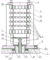
FIG. 2 is a cross-sectional view of the overall structure of the present application;
fig. 3 is a schematic view of a positioning structure of the main body on the base.
In the figure:
1. a base; 2. a main body; 3. a bolt; 4. blocking; 5. a T-bolt; 6. a shoulder nut; 7. compressing the rubber; 8. a burr avoiding groove; 11. indexing the elliptical bushing holes; 12. a circular groove; 13. a fixed shaft; 14. a flat bearing; 21. a base plate; 22. a column; 23. hollowing out the positioning sleeve; 24. positioning a plate; 25. a shouldered bushing; 26. a main body compression block; 27. a compression screw; 28. a part pressing block; 29. a compression nut; 211. indexing the bushing hole; 221. a T-shaped slot; 241. and (4) a notch.
Detailed Description
The technical solutions for achieving the objects of the present invention are further described below by specific examples, and it should be noted that the technical solutions claimed in the present application include, but are not limited to, the following examples.
Example 1
The embodiment discloses a hole making device for a deep-cylinder thin-wall part, which is shown in the attached drawings 1-3 of the specification, and comprises a base 1 and a main body 2, wherein the main body 2 is arranged on the base 1, the base 1 is correspondingly fixed on a machine tool, the main body 2 can rotate around the axis of the base 1 relative to the base 1, the center of the base 1 is provided with a coaxial circular groove 12 and a fixed shaft 13, the fixed shaft is contained in the circular groove 12, the periphery of the base 1 is provided with a bolt hole, a bolt 3 is arranged in the bolt hole, the base 1 is fixed on the machine tool through a bolt structure, the base 1 is also provided with an indexing elliptical bush hole 11 for fixing the main body, and further, a plane bearing 14 is arranged in the circular groove 12; the main body 2 mainly comprises a bottom plate 21, an upright post 22, a hollowed-out positioning sleeve 23, a positioning plate 24, a shouldered bushing 25, a main body pressing block 26, a pressing screw 27, a part pressing block 28 and a pressing nut 29, wherein the upright post 22 is uniformly fixed on the bottom plate 21 along the circumferential direction of the bottom plate 21, the hollowed-out positioning sleeve 23 is arranged between the upright posts 22 and fixedly connected with the upright post 22, the positioning plate 24 is arranged at the top of the upright post 22 and fixedly connected with the upright post 22 through a T-shaped bolt 5, the shouldered bushing 25, the main body pressing block 26, the pressing screw 27, the part pressing block 28 and the pressing nut 29 are positioned in a space enclosed by the hollowed-out positioning sleeve 23, the bottom plate 21 is directly connected with the base 1, a through hole matched with the fixing shaft 13 is arranged at the center of the bottom plate 21, the shouldered bushing 25 is arranged in the through hole, the plane bearing 14 is clamped between the, the fixed shaft 13 is located in the shouldered bushing 25, the main body pressing block 26 is arranged on the shouldered bushing 25, a through hole for the pressing screw 27 to pass through and a threaded hole matched with the pressing screw 27 are respectively formed in the main body pressing block 26 and the fixed shaft 13, one end of the pressing screw 27 is located in the threaded hole, the other end of the pressing screw 27 penetrates through the through hole in the main body pressing block 26 and is connected with the part pressing block 28, the pressing screw 27 is further sleeved with a pressing nut 29, the pressing nut 29 is located between the part pressing block 28 and the main body pressing block 26, threads of the pressing screw 26 and the threaded hole are trapezoidal threads, furthermore, the bottom plate 21 is uniformly provided with a plurality of indexing bushing holes 211 along the circumferential direction, a plug pin 3 is arranged in one indexing bushing hole 211, and plugs 4 are respectively arranged in the rest indexing bushing holes 211.
The overall working principle of the device is as follows:
the part to be processed is placed into the hollowed-out positioning sleeve 23 from the top of the main body 2, the part is placed on the part pressing block 28 and is in direct contact with the pressing rubber 7 arranged on the upper surface of the part pressing block 28, positioning of the part in the X direction and the Y direction is completed at the moment, then the positioning plate 24 is installed above the stand column 22, the positioning plate 24 is locked by the T-shaped bolt 5 and the shoulder nut 6, and the part is positioned in the Z direction. After the part is positioned, the compression screw 27 is rotated clockwise, so that the part compression block 28 at the end part of the compression screw 27 is driven to move upwards, under the combined action of the part compression block 28 and the positioning plate 24, the part is compressed to be integrated with the main body 2, then the main body 2 is rotated, the indexing bushing hole 211 without the plug 4 on the bottom plate 21 is aligned with the indexing elliptical bushing hole 11 on the base 1, the bolt 3 is inserted, the positioning and indexing of the main body 2 on the base 1 are completed, then the compression nut 29 on the compression screw 27 is rotated clockwise, under the action of the compression nut 29, the main body compression block 26 moves downwards, the compression of the main body 2 and the base 1 is realized, and after the positioning and the compression are completed, the first group of holes of the part is processed. After the first set of holes of the part are machined, the compression nut 29 is loosened and the bolt 3 is removed, then the plug 4 is removed and the body 2 is rotated so that the indexing bushing hole 211 after the plug 4 is removed is aligned with the indexing elliptical bushing hole 11 on the base 1, then the bolt 3 is inserted again, the body 2 is pressed on the base 1 by using the compression nut 29, then the second set of holes of the part are machined, and the rest of the holes are analogized in turn until all the holes are machined.
The method and the device aim at the conditions that the quality of the machined hole of the existing deep-cylinder thin-wall part is poor and the overall qualified rate is low, corresponding improvement is carried out on the structure of process equipment adopted in hole making in a targeted mode, and the quality of all machined holes of the part is guaranteed. When the process equipment is used initially, all the plugs are placed in the corresponding indexing bushing holes, after one group of holes are machined, one plug is correspondingly taken down and the main body is rotated, so that the indexing bushing hole after the plug is taken down is aligned with the indexing elliptical bushing hole, then the plug is inserted to complete the positioning of the main body, then the main body is pressed by the compression nut, the next group of holes of the part are machined continuously, and after all the plugs are taken out, all the holes representing the part are machined completely, so that the part can be effectively prevented from being drilled in a missing mode or being drilled repeatedly.
Example 2
The embodiment discloses a hole making device for a deep-cylinder thin-wall part, which is shown in the attached drawings 1-3 of the specification, and comprises a base 1 and a main body 2, wherein the main body 2 is arranged on the base 1, the base 1 is correspondingly fixed on a machine tool, the main body 2 can rotate around the axis of the base 1 relative to the base 1, the center of the base 1 is provided with a coaxial circular groove 12 and a fixed shaft 13, the fixed shaft is contained in the circular groove 12, the periphery of the base 1 is provided with a bolt hole, a bolt 3 is arranged in the bolt hole, the base 1 is fixed on the machine tool through a bolt structure, the base 1 is also provided with an indexing elliptical bush hole 11 for fixing the main body, and further, a plane bearing 14 is arranged in the circular groove 12; the main body 2 mainly comprises a bottom plate 21, an upright post 22, a hollowed-out positioning sleeve 23, a positioning plate 24, a shouldered bushing 25, a main body pressing block 26, a pressing screw 27, a part pressing block 28 and a pressing nut 29, wherein the upright post 22 is uniformly fixed on the bottom plate 21 along the circumferential direction of the bottom plate 21, the hollowed-out positioning sleeve 23 is arranged between the upright posts 22 and fixedly connected with the upright post 22, the positioning plate 24 is arranged at the top of the upright post 22 and fixedly connected with the upright post 22 through a T-shaped bolt 5, the shouldered bushing 25, the main body pressing block 26, the pressing screw 27, the part pressing block 28 and the pressing nut 29 are positioned in a space enclosed by the hollowed-out positioning sleeve 23, the bottom plate 21 is directly connected with the base 1, a through hole matched with the fixing shaft 13 is arranged at the center of the bottom plate 21, the shouldered bushing 25 is arranged in the through hole, the plane bearing 14 is clamped between the, the fixed shaft 13 is located in the shouldered bushing 25, the main body pressing block 26 is arranged on the shouldered bushing 25, a through hole for the pressing screw 27 to pass through and a threaded hole matched with the pressing screw 27 are respectively formed in the main body pressing block 26 and the fixed shaft 13, one end of the pressing screw 27 is located in the threaded hole, the other end of the pressing screw 27 penetrates through the through hole in the main body pressing block 26 and is connected with the part pressing block 28, the pressing screw 27 is further sleeved with a pressing nut 29, the pressing nut 29 is located between the part pressing block 28 and the main body pressing block 26, threads of the pressing screw 26 and the threaded hole are trapezoidal threads, furthermore, the bottom plate 21 is uniformly provided with a plurality of indexing bushing holes 211 along the circumferential direction, a plug pin 3 is arranged in one indexing bushing hole 211, and plugs 4 are respectively arranged in the rest indexing bushing holes 211.
The overall working principle of the device is as follows:
the part to be processed is placed into the hollowed-out positioning sleeve 23 from the top of the main body 2, the part is placed on the part pressing block 28 and is in direct contact with the pressing rubber 7 arranged on the upper surface of the part pressing block 28, positioning of the part in the X direction and the Y direction is completed at the moment, then the positioning plate 24 is installed above the stand column 22, the positioning plate 24 is locked by the T-shaped bolt 5 and the shoulder nut 6, and the part is positioned in the Z direction. After the part is positioned, the compression screw 27 is rotated clockwise, so that the part compression block 28 at the end part of the compression screw 27 is driven to move upwards, under the combined action of the part compression block 28 and the positioning plate 24, the part is compressed to be integrated with the main body 2, then the main body 2 is rotated, the indexing bushing hole 211 without the plug 4 on the bottom plate 21 is aligned with the indexing elliptical bushing hole 11 on the base 1, the bolt 3 is inserted, the positioning and indexing of the main body 2 on the base 1 are completed, then the compression nut 29 on the compression screw 27 is rotated clockwise, under the action of the compression nut 29, the main body compression block 26 moves downwards, the compression of the main body 2 and the base 1 is realized, and after the positioning and the compression are completed, the first group of holes of the part is processed. After the first set of holes of the part are machined, the compression nut 29 is loosened and the bolt 3 is removed, then the plug 4 is removed and the body 2 is rotated so that the indexing bushing hole 211 after the plug 4 is removed is aligned with the indexing elliptical bushing hole 11 on the base 1, then the bolt 3 is inserted again, the body 2 is pressed on the base 1 by using the compression nut 29, then the second set of holes of the part are machined, and the rest of the holes are analogized in turn until all the holes are machined.
The method and the device aim at the conditions that the quality of the machined hole of the existing deep-cylinder thin-wall part is poor and the overall qualified rate is low, corresponding improvement is carried out on the structure of process equipment adopted in hole making in a targeted mode, and the quality of all machined holes of the part is guaranteed. When the process equipment is used initially, all the plugs are placed in the corresponding indexing bushing holes, after one group of holes are machined, one plug is correspondingly taken down and the main body is rotated, so that the indexing bushing hole after the plug is taken down is aligned with the indexing elliptical bushing hole, then the plug is inserted to complete the positioning of the main body, then the main body is pressed by the compression nut, the next group of holes of the part are machined continuously, and after all the plugs are taken out, all the holes representing the part are machined completely, so that the part can be effectively prevented from being drilled in a missing mode or being drilled repeatedly.
Preferably, a T-shaped groove 221 is formed at the top of the upright post 22, a notch 241 is correspondingly formed on the positioning plate 24, one end of the T-shaped bolt 5 is located in the T-shaped groove 221, and the other end of the T-shaped bolt penetrates through the T-shaped groove 221 and the notch 241 and is locked by the shoulder nut 6.
Preferably, the surface of the part pressing block 28 is provided with a pressing rubber 7. The compression rubber 7 can increase the friction between the part and the body 2, making the compression more reliable and also protecting the part.
Preferably, a burr avoiding groove 8 is formed in the inner wall of the hollowed-out positioning sleeve 23. Under the effect that groove 8 was kept away to the burr, it is easier to take out from the major structure after parts machining, also can reduce the scratch to the part simultaneously to guarantee parts machining quality.
Example 3
The embodiment discloses a hole making device for a deep-cylinder thin-wall part, which specifically comprises the following steps:
s1, placing a deep-cylinder thin-wall part on a part pressing block 28 in a hollowed-out positioning sleeve 23 from the top of a main body 2, enabling the bottom of the deep-cylinder thin-wall part to be directly contacted with a pressing rubber 7 on the upper surface of the part pressing block 28, and then installing a positioning plate 24 on the top of an upright column 22 and pressing the positioning plate through a T-shaped bolt 5 and a nut 6 with a shoulder;
s2, clockwise rotating the compression screw 27 to drive the part compression block 28 to move upwards, compressing the part under the action of the part compression block 28 and the positioning plate 24 above the part compression block, and enabling the part and the main body 2 to be integrated;
s3, rotating the main body 2 to enable one of the indexing bushing holes 211 on the bottom plate 21 of the main body 2 to be aligned with the indexing elliptical bushing hole 11 on the base 1 and inserting the plug pin 3, completing the positioning and indexing of the main body 2 on the base 1, and placing the plugs 4 in the rest indexing bushing holes 211 on the bottom plate 21;
s4, clockwise rotating a compression nut 29 sleeved on the compression screw 27, and enabling the main body compression block 26 to move downwards under the action of the compression nut 29 to realize compression of the main body 2 and the base 1;
s5, after the main body 2 is positioned and compressed, a first group of holes of the deep-cylinder thin-wall part are machined, after the first group of holes are machined, the compression nut 29 is loosened, the plug pin 3 is taken out, the plug 4 is taken down and the main body 2 is rotated, the indexing bushing hole 211 with the plug 4 taken down is aligned with the indexing elliptical bushing hole 11 in the base 1 and then the plug pin 3 is inserted, and meanwhile, the compression nut 29 is rotated to compress the main body 2 on the base 1 again and the next group of holes are machined;
s6, after each group of holes are machined, correspondingly removing one plug 4, rotating the main body 2 to align the indexing bushing hole 211 after the plug 4 is removed with the indexing elliptical bushing hole 11 on the base 1, then inserting the bolt 3 to complete the positioning of the main body 2, then rotating the compression nut 29 to compress the main body 2 on the base 1 again, so as to start machining the next group of holes of the part, and when all the plugs 4 in all the indexing bushing holes 211 on the bottom plate 21 are completely taken out, all the holes of the part are machined;
s7, after the parts are machined, the compression screws 27 and the shoulder nuts 6 are loosened, the positioning plate 24 is detached from the stand column 22, then the part burr area is rotated to the burr avoiding groove 8 area formed in the inner wall of the hollowed positioning sleeve 23, and the parts are taken out from the upper side of the main body 2.
In the description of the present application, it is to be understood that the terms "center", "longitudinal", "lateral", "front", "back", "left", "right", "vertical", "horizontal", "top", "bottom", "inner", "outer", and the like indicate orientations or positional relationships based on those shown in the drawings, and are used merely for convenience in describing the present application and for simplifying the description, and do not indicate or imply that the referenced device or element must have a particular orientation, be constructed in a particular orientation, and be operated, and therefore should not be construed as limiting the scope of the present application.
In the description of the present application, it is further noted that, unless expressly stated or limited otherwise, the terms "disposed," "mounted," and "connected" are to be construed broadly, e.g., as meaning fixedly connected, detachably connected, or integrally connected; can be mechanically or electrically connected; they may be connected directly or indirectly through intervening media, or they may be interconnected between two elements. The specific meaning of the above terms in the present application can be understood in a specific case by those of ordinary skill in the art.
The foregoing is directed to embodiments of the present invention, which are not limited thereto, and any simple modifications and equivalents thereof according to the technical spirit of the present invention may be made within the scope of the present invention.
Claims (5)
1. The utility model provides a system hole device of deep cylinder thin wall part which characterized in that: the machine tool comprises a base (1) and a main body (2) arranged on the base (1), wherein the main body (2) can rotate around the axis of the base (1) relative to the base, and the base (1) is arranged on the machine tool; the base (1) is provided with an indexing elliptical bush hole (11), a coaxial circular groove (12) and a fixed shaft (13), the fixed shaft (13) is contained in the circular groove (12), and a plane bearing (14) is further arranged in the circular groove (12); the main body (2) comprises a bottom plate (21), an upright post (22), a hollow positioning sleeve (23), a positioning plate (24), a shouldered bushing (25), a main body pressing block (26), a pressing screw (27), a part pressing block (28) and a pressing nut (29), wherein a plurality of indexing bushing holes (211) are uniformly formed in the bottom plate (21) along the circumferential direction, a bolt (3) is arranged in one indexing bushing hole (211), plugs (4) are respectively arranged in the rest indexing bushing holes (211), a through hole is formed in the center of the bottom plate (21), the shouldered bushing (25) is arranged in the through hole, a fixing shaft (13) is positioned in the shouldered bushing (25), the main body pressing block (26) is arranged on the shouldered bushing (25), a through hole for the pressing screw (27) to pass through and a threaded hole matched with the pressing screw (27) are respectively formed in the main body pressing block (26) and the fixing shaft (13), one end of a compression screw (27) is located in the threaded hole, the other end of the compression screw penetrates through a through hole in a main body compression block (26) and is connected with a part compression block (28), a compression nut (29) is further sleeved on the compression screw (27), the stand column (22) is uniformly fixed on the bottom plate (21) along the circumferential direction of the bottom plate (21), a hollow positioning sleeve (23) is arranged between the stand column (22) and is fixedly connected with the stand column (22), and a positioning plate (24) is arranged at the top of the stand column (22) and is fixedly connected with the stand column (22) through a T-shaped bolt (5).
2. A hole making device for deep-tube thin-wall parts according to claim 1, characterized in that: the top of stand (22) is provided with T-slot (221), corresponds on locating plate (24) to be provided with breach (241), and the one end of T shape bolt (5) is located T-slot (221), and the other end runs through T-slot (221) and breach (241) and lock through shouldered nut (6).
3. A hole making device for deep-tube thin-wall parts according to claim 1, characterized in that: and the surface of the part pressing block (28) is provided with a pressing rubber (7).
4. A hole making device for deep-tube thin-wall parts according to claim 1, characterized in that: and a burr avoiding groove (8) is formed in the inner wall of the hollowed-out positioning sleeve (23).
5. A hole making method for a deep-cylinder thin-wall part is characterized by comprising the following steps: the method specifically comprises the following steps:
s1, placing a deep-cylinder thin-wall part into a hollow positioning sleeve (23) of a main body (2), enabling the bottom of the deep-cylinder thin-wall part to be in contact with a compression rubber (7) on the upper surface of a part compression block (28), installing a positioning plate (24) on the top of an upright post (22) and locking the positioning plate through a T-shaped bolt (5) and a nut (6) with a shoulder;
s2, clockwise rotating the compression screw (27) to drive the part compression block (28) to move upwards to compress the part, so that the part and the main body (2) are integrated;
s3, rotating the main body (2) to enable one indexing bushing hole (211) on the bottom plate (21) of the main body (2) to be aligned with the indexing elliptical bushing hole (11) on the base (1) and insert the bolt (3) so as to complete positioning and indexing of the main body (2) on the base (1), and placing the plugs (4) in the remaining indexing bushing holes (211) on the bottom plate (21);
s4, clockwise rotating a compression nut (29) sleeved on a compression screw (27) so as to drive a main body compression block (26) to move downwards and realize compression of the main body (2) and the base (1);
s5, after the main body (2) is positioned and compressed, a first group of holes of the deep-tube thin-wall part are machined, after the first group of holes are machined, the compression nut (29) is loosened, the plug pin (3) is taken out, the next plug (4) is taken down and the main body (2) is rotated, the indexing bushing hole (211) with the plug (4) taken down is aligned with the indexing elliptical bushing hole (11) in the base (1) and then the plug pin (3) is inserted, meanwhile, the compression nut (29) is rotated to press the main body (2) on the base (1) again, and the next group of holes are machined;
s6, after each group of holes are machined, one plug (4) is correspondingly removed, the main body (2) is rotated to enable the indexing bushing hole (211) after the plug (4) is removed to be aligned with the indexing elliptical bushing hole (11) in the base (1), then the plug pin (3) is inserted, the compression nut (29) is rotated to compress the main body (2) on the base (1) again, the next group of holes of the part are machined, and when all the plugs (4) on the bottom plate (21) are completely removed, all the holes of the part are machined;
s7, after the parts are machined, loosening the compression screws (27) and the shoulder nuts (6), disassembling the positioning plate (24) from the stand column (22), rotating the part burr area to the burr avoiding groove (8) area formed in the inner wall of the hollowed positioning sleeve (23), and taking out the parts from the upper side of the main body (2).
Priority Applications (1)
| Application Number | Priority Date | Filing Date | Title |
|---|---|---|---|
| CN202011163877.4A CN112453945B (en) | 2020-10-27 | 2020-10-27 | Hole making device and hole making method for deep-cylinder thin-wall part |
Applications Claiming Priority (1)
| Application Number | Priority Date | Filing Date | Title |
|---|---|---|---|
| CN202011163877.4A CN112453945B (en) | 2020-10-27 | 2020-10-27 | Hole making device and hole making method for deep-cylinder thin-wall part |
Publications (2)
| Publication Number | Publication Date |
|---|---|
| CN112453945A true CN112453945A (en) | 2021-03-09 |
| CN112453945B CN112453945B (en) | 2022-06-14 |
Family
ID=74834585
Family Applications (1)
| Application Number | Title | Priority Date | Filing Date |
|---|---|---|---|
| CN202011163877.4A Active CN112453945B (en) | 2020-10-27 | 2020-10-27 | Hole making device and hole making method for deep-cylinder thin-wall part |
Country Status (1)
| Country | Link |
|---|---|
| CN (1) | CN112453945B (en) |
Citations (5)
| Publication number | Priority date | Publication date | Assignee | Title |
|---|---|---|---|---|
| CN202780539U (en) * | 2012-07-25 | 2013-03-13 | 南车戚墅堰机车有限公司 | Device for machining inner holes of thin-walled annular workpiece |
| CN103447567A (en) * | 2013-08-09 | 2013-12-18 | 贵州风雷航空军械有限责任公司 | Method for processing axial holes of thin-wall cone |
| US20150306721A1 (en) * | 2012-11-27 | 2015-10-29 | Magerl Feinmechanik Gmbh | Workpiece Holder Device and Method for Mounting a Workpiece in a Workpiece Holding Device |
| CN207087366U (en) * | 2017-06-23 | 2018-03-13 | 上海马力索精密机械有限公司 | A kind of thin-walled parts found Vehicle Processing frock |
| CN207103917U (en) * | 2017-06-30 | 2018-03-16 | 南通职业大学 | The uniform hole machined special drill press fixture of output shaft |
-
2020
- 2020-10-27 CN CN202011163877.4A patent/CN112453945B/en active Active
Patent Citations (5)
| Publication number | Priority date | Publication date | Assignee | Title |
|---|---|---|---|---|
| CN202780539U (en) * | 2012-07-25 | 2013-03-13 | 南车戚墅堰机车有限公司 | Device for machining inner holes of thin-walled annular workpiece |
| US20150306721A1 (en) * | 2012-11-27 | 2015-10-29 | Magerl Feinmechanik Gmbh | Workpiece Holder Device and Method for Mounting a Workpiece in a Workpiece Holding Device |
| CN103447567A (en) * | 2013-08-09 | 2013-12-18 | 贵州风雷航空军械有限责任公司 | Method for processing axial holes of thin-wall cone |
| CN207087366U (en) * | 2017-06-23 | 2018-03-13 | 上海马力索精密机械有限公司 | A kind of thin-walled parts found Vehicle Processing frock |
| CN207103917U (en) * | 2017-06-30 | 2018-03-16 | 南通职业大学 | The uniform hole machined special drill press fixture of output shaft |
Also Published As
| Publication number | Publication date |
|---|---|
| CN112453945B (en) | 2022-06-14 |
Similar Documents
| Publication | Publication Date | Title |
|---|---|---|
| CN108857518B (en) | Boring fixture for machining two space intersecting holes in special-shaped piece and machining method | |
| CN107297525A (en) | A kind of motor flange drill jig | |
| CN112453945B (en) | Hole making device and hole making method for deep-cylinder thin-wall part | |
| CN211218801U (en) | Cambered surface drilling device | |
| CN210818531U (en) | Indexable clamp for coupler | |
| CN2873374Y (en) | Porous drill mold | |
| CN111872706A (en) | Hole site processing tool | |
| CN212169693U (en) | Special clamp for milling plane of flange plate | |
| CN211490523U (en) | Motor bearing cap mills oil groove and adds clamping apparatus | |
| CN113369936A (en) | Device for machining circumferential inclined holes of nozzle nuts of aircraft engines | |
| CN220480926U (en) | Arc surface positioning and processing device | |
| CN216326574U (en) | Axial symmetrical key groove processing and positioning device | |
| CN212351092U (en) | Hole site processing tool | |
| CN218903716U (en) | Drilling jig for machining circumference different-direction inclined holes | |
| CN217225743U (en) | Frock for diaphragm capsule | |
| CN214237167U (en) | Rapid clamping device | |
| CN214871716U (en) | Machining cutter and machine tool comprising same | |
| CN210997570U (en) | Outer hexagonal adds clamping apparatus | |
| CN110216581B (en) | Horizontal fixture for grinding rotor slot | |
| CN217531624U (en) | Rotating structure for glue injection of filter element end cover | |
| CN113352476B (en) | Frame and big cutter convenient to installation | |
| CN210648673U (en) | Cylinder barrel universal drill jig | |
| CN211053590U (en) | Special puller for disassembling motor insert | |
| CN219416515U (en) | Grinding force tester | |
| CN113020918B (en) | Processing method of hydrogen return pump rotor |
Legal Events
| Date | Code | Title | Description |
|---|---|---|---|
| PB01 | Publication | ||
| PB01 | Publication | ||
| SE01 | Entry into force of request for substantive examination | ||
| SE01 | Entry into force of request for substantive examination | ||
| GR01 | Patent grant | ||
| GR01 | Patent grant |