CN112429792A - Sludge discharge device for sewage treatment - Google Patents
Sludge discharge device for sewage treatment Download PDFInfo
- Publication number
- CN112429792A CN112429792A CN202011323974.5A CN202011323974A CN112429792A CN 112429792 A CN112429792 A CN 112429792A CN 202011323974 A CN202011323974 A CN 202011323974A CN 112429792 A CN112429792 A CN 112429792A
- Authority
- CN
- China
- Prior art keywords
- moving
- sewage treatment
- rods
- rod
- wheel
- Prior art date
- Legal status (The legal status is an assumption and is not a legal conclusion. Google has not performed a legal analysis and makes no representation as to the accuracy of the status listed.)
- Withdrawn
Links
Images


Classifications
-
- C—CHEMISTRY; METALLURGY
- C02—TREATMENT OF WATER, WASTE WATER, SEWAGE, OR SLUDGE
- C02F—TREATMENT OF WATER, WASTE WATER, SEWAGE, OR SLUDGE
- C02F1/00—Treatment of water, waste water, or sewage
-
- B—PERFORMING OPERATIONS; TRANSPORTING
- B08—CLEANING
- B08B—CLEANING IN GENERAL; PREVENTION OF FOULING IN GENERAL
- B08B9/00—Cleaning hollow articles by methods or apparatus specially adapted thereto
- B08B9/08—Cleaning containers, e.g. tanks
- B08B9/087—Cleaning containers, e.g. tanks by methods involving the use of tools, e.g. brushes, scrapers
-
- C—CHEMISTRY; METALLURGY
- C02—TREATMENT OF WATER, WASTE WATER, SEWAGE, OR SLUDGE
- C02F—TREATMENT OF WATER, WASTE WATER, SEWAGE, OR SLUDGE
- C02F2201/00—Apparatus for treatment of water, waste water or sewage
- C02F2201/002—Construction details of the apparatus
-
- C—CHEMISTRY; METALLURGY
- C02—TREATMENT OF WATER, WASTE WATER, SEWAGE, OR SLUDGE
- C02F—TREATMENT OF WATER, WASTE WATER, SEWAGE, OR SLUDGE
- C02F2201/00—Apparatus for treatment of water, waste water or sewage
- C02F2201/002—Construction details of the apparatus
- C02F2201/004—Seals, connections
-
- C—CHEMISTRY; METALLURGY
- C02—TREATMENT OF WATER, WASTE WATER, SEWAGE, OR SLUDGE
- C02F—TREATMENT OF WATER, WASTE WATER, SEWAGE, OR SLUDGE
- C02F2303/00—Specific treatment goals
- C02F2303/14—Maintenance of water treatment installations
Landscapes
- Engineering & Computer Science (AREA)
- Mechanical Engineering (AREA)
- Life Sciences & Earth Sciences (AREA)
- Hydrology & Water Resources (AREA)
- Environmental & Geological Engineering (AREA)
- Water Supply & Treatment (AREA)
- Chemical & Material Sciences (AREA)
- Organic Chemistry (AREA)
- Treatment Of Sludge (AREA)
Abstract
The invention belongs to the field of sewage treatment, and particularly relates to a sludge discharge device for sewage treatment, which aims at solving the problems that the existing sludge cleaning equipment is poor in cleaning effect, low in cleaning efficiency and time-consuming and labor-consuming due to the fact that manual auxiliary cleaning is needed. The sludge cleaning equipment is reasonable in structure, convenient to operate, good in cleaning effect, good in equipment universality, convenient to use in different treatment tanks, high in cleaning efficiency, free of manual auxiliary cleaning, time-saving and labor-saving.
Description
Technical Field
The invention relates to the technical field of sewage treatment, in particular to a sludge discharge device for sewage treatment.
Background
Sewage treatment is classified according to the source of sewage, and is generally classified into production sewage treatment and domestic sewage treatment. The production sewage comprises industrial sewage, agricultural sewage, medical sewage and the like, the domestic sewage is sewage generated in daily life and is a complex mixture of various forms of inorganic matters and organic matters, the sewage treatment is a process for purifying the sewage to meet the requirement of discharging the sewage into a certain water body or reusing the sewage, and a large amount of sludge is accumulated at the bottom of a general sewage treatment pool after long-time sedimentation and needs to be cleaned regularly;
current patent CN210698946U discloses a mud device is arranged to sewage treatment pond, and this mud device of arranging can gather together and unified the inhaling mud bottom the sewage treatment pond when arranging mud, however, this current silt clean-up equipment still has following technical problem at least: 1) the device is only simply to take the mud of bottom of the pool out through the mud pump, but its lateral wall and the adnexed a large amount of silt of diapire to handling the pond can't clear up, 2) current row's mud device needs the manual work to scrape a plurality of inner walls in proper order, and can't clear up a plurality of inner walls fast with automizing.
Disclosure of Invention
The invention aims to solve the defects that in the prior art, sludge cleaning equipment is poor in cleaning effect and low in cleaning efficiency, manual auxiliary cleaning is needed, and time and labor are wasted.
In order to achieve the purpose, the invention adopts the following technical scheme:
a sludge discharge device for sewage treatment comprises a moving frame, wherein a treatment pool is arranged at the bottom of the moving frame, a sludge pump is fixedly arranged at the top of the moving frame, a sludge pumping pipe is fixedly arranged on a feed inlet of the sludge pump, the sludge pumping pipe is arranged in the treatment pool, a connecting column is fixedly arranged at the bottom of the moving frame, a moving groove is formed in the bottom of the connecting column, a threaded rod is slidably arranged in the moving groove, a connecting plate is fixedly arranged at the bottom of the threaded rod, the connecting plate is movably arranged in the treatment pool, a first rotating wheel is in threaded connection with the threaded rod, the first rotating wheel is rotatably arranged at the bottom of the connecting column, a first motor is fixedly arranged at one side of the connecting column, a second rotating wheel is fixedly connected onto an output shaft of the first motor, the second rotating wheel is meshed with the first rotating wheel, two fixing rods are fixedly arranged, two end scraper blades all contact with the bottom inner wall of treatment tank, the both sides of connecting plate are all seted up flutedly, equal slidable mounting has the carriage release lever in two recesses, the equal fixed mounting of one end that two carriage release levers were kept away from each other has the side scraper blade, two side scraper blades contact with the both sides inner wall of treatment tank respectively, the screw thread groove has all been seted up to the one end that two carriage release levers are close to each other, equal threaded connection has first lead screw in two screw thread grooves, same fixed orifices has been seted up on the one side inner wall that two recesses are close to each other, the one end that two first lead screws are close to each other all rotates and installs in the fixed orifices, the one end fixed mounting that two first lead screws are close to each other has same worm wheel, the connecting hole has been seted up on the bottom inner wall of fixed orifices, the connecting hole internal rotation installs.
Preferably, two spread grooves have been seted up to the bottom of removal frame, all rotate in two spread grooves and install first gyro wheel, and two first gyro wheels all contact with the top in handling the pond.
Preferably, two removal holes have been seted up at the top of removal frame, and equal slidable mounting has the removal seat in two removal holes, and the control tank has all been seted up to one side that two removal seats kept away from each other, all rotates in two control tanks and installs the second gyro wheel, and two second gyro wheels contact with the both sides inner wall of handling the pond respectively, remove the second gyro wheel removal that the seat drove the correspondence, and the second gyro wheel contacts with the inner wall of handling the pond, and first gyro wheel contacts with the top of handling the pond.
Preferably, the through holes are formed in the inner walls of the bottoms of the two control grooves, round rods are fixedly mounted at the bottoms of the two second rollers, the two round rods are rotatably mounted in the corresponding two through holes, and first chain wheels are fixedly mounted at the bottoms of the two round rods.
Preferably, two equal fixed mounting in one side that remove the seat and be close to each other have the second motor, all fixed cover is equipped with the second sprocket on the output shaft of two second motors, and the second sprocket meshes with the first sprocket that corresponds has same chain, and the second motor drives the second sprocket and rotates, and the second sprocket passes through the chain and drives first sprocket rotation.
Preferably, threaded holes are formed in one side of each of the two movable seats, the second screw rods are installed in the two movable holes in a rotating mode, the second screw rods are connected into corresponding threaded holes in a threaded mode, first belt pulleys are fixedly sleeved on the two second screw rods, the first belt pulleys drive the corresponding second screw rods to rotate, and the second screw rods drive the corresponding movable seats to move.
Preferably, the top fixed mounting who removes the frame has two connecting seats, and two connecting seats rotate and install same connecting rod, and the equal fixed mounting in both ends of connecting rod has the second band pulley, and the second band pulley has same belt with the meshing of the first band pulley that corresponds, and fixed cover is equipped with the handle on the connecting rod, and the second band pulley drives the belt motion that corresponds, and the belt drives the first band pulley motion that corresponds.
Preferably, the inner wall of the moving hole is provided with a sliding groove, the moving seat is fixedly provided with a sliding block, the sliding block is slidably mounted in the sliding groove, the moving seat moves to drive the sliding block to slide in the sliding groove, and the moving seat can be moved in an auxiliary mode.
Preferably, the fixing rod (11) is a threaded telescopic rod.
Preferably, the fixed rod (11) is fixedly connected with the bottom scraper (12).
Preferably, the fixed rod (11) is hinged or ball-connected with the bottom scraper (12).
Compared with the prior art, the invention has the beneficial effects that:
1) according to the scheme, the movable frame is placed on the treatment tank needing to discharge the sludge, the second idler wheel moves, the second idler wheel is in contact with the inner wall of the treatment tank, the connecting plate can drive the two bottom scraping plates to move in the treatment tank, the penetration depth of the two bottom scraping plates can be adjusted, and the movable frame is suitable for cleaning the treatment tank with any three-dimensional size;
2) the fixed rods are threaded telescopic rods, when the device is used, the length of each fixed rod is completely screwed out and tightly screwed by rotating the bottom scraper, when the device is not used, the fixed rods are screwed and retracted, the bottom ends of the two fixed rods are hinged or fixedly provided with the bottom scraper by a bolt through ball mounting, so that the bottom scraper 12 can rotate at the joint of the fixed rods 11, and the bottom scraper can be suitable for treatment tanks with different slopes of the bottom wall, such as slope tank bottoms, ridge tank bottoms and the like;
3) when supporting the device body through first gyro wheel and second gyro wheel, be convenient for remove along handling pond length direction for this device is automatic to be accomplished and is cleared up when a plurality of lateral walls of handling the pond. The automatic cleaning device has better universality on the whole, is suitable for cleaning the treatment tanks with different lengths, widths, depths and bottom wall slopes, is convenient to use in different treatment tanks, has higher cleaning efficiency, can simultaneously realize automatic cleaning of three side walls, does not need manual auxiliary cleaning, and is time-saving and labor-saving.
Drawings
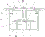
FIG. 1 is a schematic view of a front view structure according to the present invention;
FIG. 2 is a schematic structural view of a connecting plate, a fixing rod and a bottom scraper according to the present invention;
FIG. 3 is a schematic view of part A of the structure proposed by the present invention;
FIG. 4 is a schematic structural diagram of part B according to the present invention;
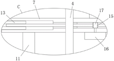
fig. 5 is a schematic structural diagram of part C according to the present invention.
In the figure: 1. a movable frame; 2. a treatment tank; 3. a mud pump; 4. a mud pumping pipe; 5. connecting columns; 6. a threaded rod; 7. a connecting plate; 8. a first rotating wheel; 9. a second rotating wheel; 10. a first motor; 11. fixing the rod; 12. a bottom squeegee; 13. a travel bar; 14. a side flight; 15. a worm gear; 16. a turntable; 17. a worm; 18. a first roller; 19. a movable seat; 20. a second roller; 21. a first sprocket; 22. a second motor; 23. a second sprocket; 24. a chain; 25. a second lead screw; 26. a first pulley; 27. a second pulley; 28. a belt; 29. a connecting seat; 30. a handle.
Detailed Description
The technical solutions in the embodiments of the present invention will be clearly and completely described below with reference to the drawings in the embodiments of the present invention, and it is obvious that the described embodiments are only a part of the embodiments of the present invention, and not all of the embodiments.
Unless otherwise defined, technical or scientific terms used herein shall have the ordinary meaning as understood by one of ordinary skill in the art to which this invention belongs. The use of "first," "second," and similar terms in the description and claims of this patent does not denote any order, quantity, or importance, but rather the terms are used to distinguish one element from another. Also, the use of the terms "a" or "an" and the like do not denote a limitation of quantity, but rather denote the presence of at least one.
Example one
Referring to fig. 1-5, a sludge discharging device for sewage treatment comprises a moving frame 1, a treatment pool 2 is arranged at the bottom of the moving frame 1, a sludge pump 3 is fixedly installed at the top of the moving frame 1, a sludge pumping pipe 4 is fixedly installed on a feed inlet of the sludge pump 3, the sludge pumping pipe 4 is installed in the treatment pool 2, a connecting column 5 is fixedly installed at the bottom of the moving frame 1, a moving groove is formed in the bottom end of the connecting column 5, a threaded rod 6 is slidably installed in the moving groove, a connecting plate 7 is fixedly installed at the bottom end of the threaded rod 6, the connecting plate 7 is movably installed in the treatment pool 2, a first rotating wheel 8 is in threaded connection with the threaded rod 6, the first rotating wheel 8 is rotatably installed at the bottom end of the connecting column 5, a first motor 10 is fixedly installed at one side of the connecting column 5, a second rotating wheel 9 is fixedly connected with an output shaft of, two fixed rods 11 are fixedly arranged at the bottom of the connecting plate 7, bottom scraping plates 12 are fixedly arranged at the bottom ends of the two fixed rods 11, the two bottom scraping plates 12 are both contacted with the inner wall of the bottom of the treatment pool 2, grooves are respectively arranged at both sides of the connecting plate 7, moving rods 13 are respectively and slidably arranged in the grooves, side scraping plates 14 are respectively fixedly arranged at the ends far away from each other of the two moving rods 13, the two side scraping plates 14 are respectively contacted with the inner walls at both sides of the treatment pool 2, thread grooves are respectively arranged at the ends close to each other of the two moving rods 13, first lead screws are respectively and threadedly connected in the two thread grooves, the same fixed hole is arranged on the inner wall at one side close to each other of the two grooves, the ends close to each other of the two first lead screws are rotatably arranged in the fixed holes, the same worm wheel 15 is fixedly arranged, the connecting hole is rotatably provided with a connecting block, the top end of the connecting block is fixedly provided with a worm 17, the worm 17 is meshed with the worm wheel 15, and the bottom end of the connecting block is fixedly provided with a turntable 16.
In this embodiment, two spread grooves have been seted up to the bottom of removing frame 1, all rotate in two spread grooves and install first gyro wheel 18, and two first gyro wheels 18 all contact with the top of handling cell 2.
In this embodiment, two removal holes have been seted up at the top of removal frame 1, two equal slidable mounting have a removal seat 19 in the removal hole, two remove one side that seat 19 kept away from each other and have all seted up the control flume, all rotate in two control flumes and install second gyro wheel 20, two second gyro wheels 20 contact with the both sides inner wall of handling pond 2 respectively, it drives the second gyro wheel 20 removal that corresponds to remove seat 19, second gyro wheel 20 contacts with the inner wall of handling pond 2, first gyro wheel 18 contacts with the top of handling pond 2.
In this embodiment, all seted up the through-hole on the bottom inner wall of two control slots, the equal fixed mounting in bottom of two second gyro wheels 20 has the round bar, and two round bars rotate to be installed in two through-holes that correspond, and the equal fixed mounting in bottom of two round bars has first sprocket 21.
In this embodiment, two equal fixed mounting in one side that remove seat 19 and be close to each other have second motor 22, all fix the cover on two second motor 22's the output shaft and be equipped with second sprocket 23, and second sprocket 23 meshes with the first sprocket 21 that corresponds and has same chain 24, and second motor 22 drives second sprocket 23 and rotates, and second sprocket 23 passes through chain 24 and drives first sprocket 21 and rotate.
In this embodiment, threaded holes are all opened in one side of two removal seats 19, and two removal downthehole all rotate and install second lead screw 25, and second lead screw 25 threaded connection is in the threaded hole that corresponds, and two last all fixed covers of second lead screw 25 are equipped with first band pulley 26, and first band pulley 26 drives the second lead screw 25 rotation that corresponds for second lead screw 25 drives the removal seat 19 that corresponds and removes.
In this embodiment, two connecting seats 29 are fixedly mounted at the top of the movable frame 1, two connecting seats 29 rotate to be mounted with the same connecting rod, the two ends of the connecting rod are fixedly mounted with the second belt wheel 27, the second belt wheel 27 is meshed with the corresponding first belt wheel 26 to form the same belt 28, the connecting rod is fixedly sleeved with the handle 30, the second belt wheel 27 drives the corresponding belt 28 to move, and the belt 28 drives the corresponding first belt wheel 26 to move.
In this embodiment, seted up the spout on the inner wall in removal hole, fixed mounting has the slider on removing the seat 19, and slider slidable mounting is in the spout, removes the seat 19 and removes and drive the slider and slide in the spout, can assist to remove the seat 19 and remove.
Example two
Referring to fig. 1-5, a sludge discharging device for sewage treatment comprises a moving frame 1, a treatment tank 2 is arranged at the bottom of the moving frame 1, a sludge pump 3 is fixedly installed at the top of the moving frame 1 through bolts, a sludge pumping pipe 4 is fixedly installed on a feed inlet of the sludge pump 3 through bolts, the sludge pumping pipe 4 is installed in the treatment tank 2, a connecting column 5 is fixedly installed at the bottom of the moving frame 1 through bolts, a moving groove is formed in the bottom end of the connecting column 5, a threaded rod 6 is slidably installed in the moving groove, a connecting plate 7 is fixedly installed at the bottom end of the threaded rod 6 through bolts, the connecting plate 7 is movably installed in the treatment tank 2, a first rotating wheel 8 is in threaded connection with the threaded rod 6, the first rotating wheel 8 is rotatably installed at the bottom end of the connecting column 5, a first motor 10 is fixedly installed at one side of the connecting column 5 through bolts, a, the second rotating wheel 9 is meshed with the first rotating wheel 8, two fixing rods 11 are fixedly installed at the bottom of the connecting plate 7 through bolts, the fixing rods 11 are threaded telescopic rods, when in use, the fixing rods 11 are completely screwed out and are tightly screwed through rotating the bottom scraping plates 12, when not in use, the fixing rods 11 are screwed and contracted for storage, the bottom ends of the two fixing rods 11 are hinged or are provided with bottom scraping plates 12 through balls, as shown in figure 2, the fixing rods 11 are hinged or connected with the bottom scraping plates 12 through balls, so that the bottom scraping plates 12 can rotate at the joints with the fixing rods 11, the bottom scraping plates 12 can be applied to treatment tanks with different slopes of the bottom wall, such as slope tank bottoms, ridge tank bottoms and the like, the two bottom scraping plates 12 are in contact with the inner wall of the bottom of the treatment tank 2, grooves are formed in the two sides of the connecting plate 7, the moving rods 13 are slidably installed in the two grooves, and side scraping plates 14 are fixedly installed at, two side scraper blades 14 contact with the both sides inner wall of treatment tank 2 respectively, the thread groove has all been seted up to the one end that two carriage release levers 13 are close to each other, equal threaded connection has first lead screw in two thread grooves, same fixed orifices has been seted up on the one side inner wall that two recesses are close to each other, the one end that two first lead screws are close to each other all rotates and installs in the fixed orifices, bolt fixed mounting is passed through to the one end that two first lead screws are close to each other has same worm wheel 15, the connecting hole has been seted up on the bottom inner wall of fixed orifices, the connecting block is installed to the connecting hole internal rotation, bolt fixed mounting has worm 17 on the top of connecting block, worm 17 and worm wheel 15 mesh.
In this embodiment, two spread grooves have been seted up to the bottom of removing frame 1, all rotate in two spread grooves and install first gyro wheel 18, and two first gyro wheels 18 all contact with the top of handling cell 2.
In this embodiment, two removal holes have been seted up at the top of removal frame 1, two equal slidable mounting have a removal seat 19 in the removal hole, two remove one side that seat 19 kept away from each other and have all seted up the control flume, all rotate in two control flumes and install second gyro wheel 20, two second gyro wheels 20 contact with the both sides inner wall of handling pond 2 respectively, it drives the second gyro wheel 20 removal that corresponds to remove seat 19, second gyro wheel 20 contacts with the inner wall of handling pond 2, first gyro wheel 18 contacts with the top of handling pond 2. The first roller 18 provides a supporting force for the device, so that the device is erected on a treatment tank to be cleaned.
In this embodiment, all seted up the through-hole on the bottom inner wall of two control slots, the bottom of two second gyro wheels 20 all has the round bar through bolt fixed mounting, and two round bars rotate to be installed in two through-holes that correspond, and the bottom of two round bars all has first sprocket 21 through bolt fixed mounting.
In this embodiment, two one sides that remove seat 19 and be close to each other all have second motor 22 through bolt fixed mounting, all fixed cover is equipped with second sprocket 23 on two second motor 22's the output shaft, and second sprocket 23 meshes with the first sprocket 21 that corresponds and has same chain 24, and second motor 22 drives second sprocket 23 and rotates, and second sprocket 23 passes through chain 24 and drives first sprocket 21 and rotate.
In this embodiment, threaded holes are all opened in one side of two removal seats 19, and two removal downthehole all rotate and install second lead screw 25, and second lead screw 25 threaded connection is in the threaded hole that corresponds, and two last all fixed covers of second lead screw 25 are equipped with first band pulley 26, and first band pulley 26 drives the second lead screw 25 rotation that corresponds for second lead screw 25 drives the removal seat 19 that corresponds and removes.
In this embodiment, there are two connecting seats 29 at the top of removal frame 1 through bolt fixed mounting, and two connecting seats 29 rotate and install same connecting rod, and there is second band pulley 27 at the both ends of connecting rod all through bolt fixed mounting, and second band pulley 27 has same belt 28 with the meshing of the first band pulley 26 that corresponds, and the fixed cover is equipped with handle 30 on the connecting rod, and second band pulley 27 drives the belt 28 motion that corresponds, and belt 28 drives the first band pulley 26 motion that corresponds.
In this embodiment, seted up the spout on the inner wall in removal hole, there is the slider through bolt fixed mounting on the removal seat 19, and slider slidable mounting is in the spout, and removal seat 19 removes and drives the slider and slide in the spout, can assist removal seat 19 to remove.
In this embodiment, the movable frame 1 is placed on the treatment tank 2 requiring sludge discharge, the two bottom scrapers 12 and the two side scrapers 14 are installed in the treatment tank 2, the handle 30 is rotated, the handle 30 drives the connecting rod to rotate, the connecting rod rotates on the connecting seat 29, the connecting rod drives the two second belt wheels 27 to move, the second belt wheels 27 drive the corresponding belts 28 to move, the belts 28 drive the corresponding first belt wheels 26 to move, the first belt wheels 26 drive the corresponding second lead screws 25 to rotate, so that the second lead screws 25 drive the corresponding movable seats 19 to move, the movable seats 19 drive the corresponding second idler wheels 20 to move, the second idler wheels 20 are in contact with the inner wall of the treatment tank 2, the first idler wheels 18 are in contact with the top of the treatment tank 2, the device body is supported by the first idler wheels 18 and the second idler wheels 20, so that the device can be erected on the treatment tank to be cleaned, and the device can be adapted to the treatment tank with any width, the application range is wide. The first motor 10 drives the second rotating wheel 9 to rotate, the second rotating wheel 9 drives the first rotating wheel 8 to rotate, the first rotating wheel 8 drives the threaded rod 6 to move, the threaded rod 6 drives the connecting plate 7 to move, the connecting plate 7 can drive the two bottom scrapers 12 to move in the treatment tank 2, so that the bottom scrapers 12 are in contact with the bottom of the treatment tank, the device is adaptive to the depth of the treatment tank with any depth, the two bottom scrapers 12 are in contact with the inner wall of the bottom of the treatment tank 2, the rotating disc 16 is rotated, the rotating disc 16 drives the connecting block to rotate, the connecting block drives the worm 17 to rotate, the worm 17 drives the worm wheel 15 to rotate, the worm wheel 15 drives the two first lead screws to rotate, so that the first lead screws drive the corresponding moving rods 13 to move, the moving rods 13 drive the corresponding side scrapers 14 to move, the two side scrapers 14 move towards the directions away from each other, make the device be adapted to the processing pond of arbitrary width, second motor 22 drives second sprocket 23 and rotates, second sprocket 23 drives first sprocket 21 through chain 24 and rotates, first sprocket 21 drives the round bar and rotates, the round bar drives second gyro wheel 20 and rotates, second gyro wheel 20 rolls and drives carriage 1 and takes place to remove on the inner wall of processing pond 2, make carriage 1 drive two end scraper blades 12 and two side scraper blades 14 and remove, clear up the whole length direction of handling the pond, two end scraper blades 12 and two side scraper blades 14 remove and clear up the inner wall of handling pond 2, can realize automatic clearance to a plurality of lateral walls of handling the pond simultaneously, mud pump 3 can drive and take out mud pipe 4 and carry out silt collection to the interior of handling pond 2.
Compared with the prior art, the invention has the technical progress that: the sludge cleaning equipment has the advantages of reasonable structure, convenience in operation, better cleaning effect, better equipment universality, convenience in use in different treatment pools 2, higher cleaning efficiency, no need of manual auxiliary cleaning, time saving and labor saving.
Claims (11)
1. The utility model provides a sludge discharge device for sewage treatment, includes and removes frame (1), its characterized in that, the bottom of removing frame (1) is equipped with handles pond (2), and the top fixed mounting that removes frame (1) has mud pump (3), and fixed mounting has mud pumping pipe (4) on the feed inlet of mud pump (3), and mud pumping pipe (4) are installed in handling pond (2), the bottom fixed mounting that removes frame (1) has spliced pole (5), and the shifting chute has been seted up to the bottom of spliced pole (5), and slidable mounting has threaded rod (6) in the shifting chute, and the bottom fixed mounting of threaded rod (6) has connecting plate (7), and connecting plate (7) movable mounting is in handling pond (2), and threaded rod (6) are gone up threaded connection has first runner (8), first runner (8) rotate and install the bottom in spliced pole (5), and one side fixed mounting of spliced pole (5) has first motor (10), a second rotating wheel (9) is fixedly connected to an output shaft of the first motor (10), the second rotating wheel (9) is meshed with the first rotating wheel (8), two fixing rods (11) are fixedly installed at the bottom of the connecting plate (7), bottom scrapers (12) are arranged at the bottoms of the two fixing rods (11), the two bottom scrapers (12) are contacted with the inner wall of the bottom of the treatment pool (2), grooves are formed in the two sides of the connecting plate (7), moving rods (13) are slidably installed in the two grooves, side scrapers (14) are fixedly installed at the ends, far away from each other, of the two moving rods (13), the two side scrapers (14) are contacted with the inner walls of the two sides of the treatment pool (2), thread grooves are formed in the ends, close to each other, of the two moving rods (13), a first screw rod is connected to the two thread grooves in a threaded manner, the inner wall, on one side, close to each other, the one end that two first lead screws are close to each other all rotates and installs in the fixed orifices, and the one end fixed mounting that two first lead screws are close to each other has same worm wheel (15), has seted up the connecting hole on the bottom inner wall of fixed orifices, and the connecting hole internal rotation is installed the connecting block, and the top fixed mounting of connecting block has worm (17), worm (17) and worm wheel (15) meshing, and the bottom fixed mounting of connecting block has carousel (16).
2. The sludge discharging device for sewage treatment as claimed in claim 1, wherein the bottom of the moving frame (1) is provided with two connecting grooves, the two connecting grooves are rotatably provided with the first rollers (18), and the two first rollers (18) are contacted with the top of the treatment tank (2).
3. The sludge discharging device for sewage treatment according to claim 1, wherein the top of the moving frame (1) is provided with two moving holes, moving seats (19) are slidably mounted in the two moving holes, control grooves are formed in the sides of the two moving seats (19) far away from each other, second rollers (20) are rotatably mounted in the two control grooves, and the two second rollers (20) are respectively in contact with the inner walls of the two sides of the treatment tank (2).
4. The sludge discharging device for sewage treatment as claimed in claim 3, wherein the inner walls of the bottoms of the two control grooves are provided with through holes, the bottoms of the two second rollers (20) are fixedly provided with round rods, the two round rods are rotatably arranged in the corresponding two through holes, and the bottom ends of the two round rods are fixedly provided with the first chain wheel (21).
5. A sludge discharge device for sewage treatment according to claim 4, wherein the two moving seats (19) are fixedly provided with a second motor (22) at the side close to each other, the output shafts of the two second motors (22) are fixedly sleeved with a second chain wheel (23), and the second chain wheel (23) is meshed with the corresponding first chain wheel (21) by a same chain (24).
6. The sludge discharge device for sewage treatment as claimed in claim 3, wherein one side of each of the two moving seats (19) is provided with a threaded hole, the two moving holes are rotatably provided with a second screw rod (25), the second screw rods (25) are in threaded connection with the corresponding threaded holes, and the two second screw rods (25) are fixedly sleeved with first belt wheels (26).
7. The sludge discharging device for sewage treatment as claimed in claim 6, wherein two connecting seats (29) are fixedly installed on the top of the moving frame (1), the two connecting seats (29) are rotatably installed with a same connecting rod, a second belt wheel (27) is fixedly installed on each end of the connecting rod, the second belt wheel (27) is engaged with a same belt (28) with the corresponding first belt wheel (26), and a handle (30) is fixedly sleeved on the connecting rod.
8. The sludge discharging device for sewage treatment as claimed in claim 3, wherein the inner wall of the moving hole is provided with a sliding groove, the moving seat (19) is fixedly provided with a sliding block, and the sliding block is slidably arranged in the sliding groove.
9. The sludge discharging device for sewage treatment as claimed in claim 1, wherein the fixing rod (11) is a threaded telescopic rod.
10. The sludge discharging device for sewage treatment as claimed in claim 1, wherein the fixing rod (11) is fixedly connected with the bottom scraper (12).
11. A sludge discharge apparatus for sewage treatment as claimed in claim 1, wherein the fixing rod (11) is hinged or ball-jointed to the bottom scraper (12).
Priority Applications (1)
| Application Number | Priority Date | Filing Date | Title |
|---|---|---|---|
| CN202011323974.5A CN112429792A (en) | 2020-11-23 | 2020-11-23 | Sludge discharge device for sewage treatment |
Applications Claiming Priority (1)
| Application Number | Priority Date | Filing Date | Title |
|---|---|---|---|
| CN202011323974.5A CN112429792A (en) | 2020-11-23 | 2020-11-23 | Sludge discharge device for sewage treatment |
Publications (1)
| Publication Number | Publication Date |
|---|---|
| CN112429792A true CN112429792A (en) | 2021-03-02 |
Family
ID=74693682
Family Applications (1)
| Application Number | Title | Priority Date | Filing Date |
|---|---|---|---|
| CN202011323974.5A Withdrawn CN112429792A (en) | 2020-11-23 | 2020-11-23 | Sludge discharge device for sewage treatment |
Country Status (1)
| Country | Link |
|---|---|
| CN (1) | CN112429792A (en) |
Cited By (1)
| Publication number | Priority date | Publication date | Assignee | Title |
|---|---|---|---|---|
| CN113457255A (en) * | 2021-07-19 | 2021-10-01 | 山东科美环保技术服务有限公司 | Domestic sewage's environmental protection processing apparatus |
-
2020
- 2020-11-23 CN CN202011323974.5A patent/CN112429792A/en not_active Withdrawn
Cited By (1)
| Publication number | Priority date | Publication date | Assignee | Title |
|---|---|---|---|---|
| CN113457255A (en) * | 2021-07-19 | 2021-10-01 | 山东科美环保技术服务有限公司 | Domestic sewage's environmental protection processing apparatus |
Similar Documents
| Publication | Publication Date | Title |
|---|---|---|
| CN112429792A (en) | Sludge discharge device for sewage treatment | |
| CN108619762B (en) | Working method of pool bottom sediment cleaning device for sewage purification pool | |
| CN118104606A (en) | Circulating water fishery system based on combined natural ecological purification | |
| CN113387528A (en) | Sludge reduction treatment equipment of sedimentation tank for sewage treatment plant | |
| CN112718847A (en) | Pollute soil environmental protection treatment equipment | |
| CN116479991A (en) | Flood discharge channel dredging equipment and use method thereof | |
| CN216404002U (en) | Multistage filter equipment for industrial water treatment | |
| CN115026952A (en) | Concrete residual slurry recycling device | |
| CN111453897B (en) | Electrochemistry circulating water treatment device with advanced treatment function | |
| CN115162451A (en) | Ditch silt processing apparatus for hydraulic engineering | |
| CN210943914U (en) | Sludge discharge device for sewage treatment | |
| CN114673126A (en) | A refuse treatment device for hydraulic engineering uses | |
| CN114011122A (en) | Cleaning system for sedimentation tank of sewage treatment plant | |
| CN212024830U (en) | Sediment machine is scraped with being convenient for empty formula sewage treatment | |
| CN211189226U (en) | Mud scraper of sewage treatment equipment | |
| CN110612952B (en) | Automatic clamworm capturing device | |
| CN218969950U (en) | River course floats grass collection device | |
| CN219546736U (en) | Dyeing wastewater treatment pond | |
| CN217119438U (en) | Sludge treatment mud scraper | |
| CN221815547U (en) | Automatic sewage treatment equipment based on sedimentation ratio | |
| CN213802956U (en) | Urban domestic sewage suspended solid treatment fishing device | |
| CN219462617U (en) | Sewage treatment sedimentation tank | |
| CN215310412U (en) | Sewage treatment desilting device for industrial park | |
| CN221797103U (en) | Separating device for sewage treatment | |
| CN220530759U (en) | Sewage treatment pond mud residue cleaning device |
Legal Events
| Date | Code | Title | Description |
|---|---|---|---|
| PB01 | Publication | ||
| PB01 | Publication | ||
| SE01 | Entry into force of request for substantive examination | ||
| SE01 | Entry into force of request for substantive examination | ||
| WW01 | Invention patent application withdrawn after publication |
Application publication date: 20210302 |
|
| WW01 | Invention patent application withdrawn after publication |