CN112423703A - Auxiliary instrument for providing neuroprotection during interventional procedure - Google Patents
Auxiliary instrument for providing neuroprotection during interventional procedure Download PDFInfo
- Publication number
- CN112423703A CN112423703A CN201980035636.0A CN201980035636A CN112423703A CN 112423703 A CN112423703 A CN 112423703A CN 201980035636 A CN201980035636 A CN 201980035636A CN 112423703 A CN112423703 A CN 112423703A
- Authority
- CN
- China
- Prior art keywords
- filter
- instrument
- catheter
- sealing membrane
- emboli
- Prior art date
- Legal status (The legal status is an assumption and is not a legal conclusion. Google has not performed a legal analysis and makes no representation as to the accuracy of the status listed.)
- Pending
Links
Images


Classifications
-
- A—HUMAN NECESSITIES
- A61—MEDICAL OR VETERINARY SCIENCE; HYGIENE
- A61F—FILTERS IMPLANTABLE INTO BLOOD VESSELS; PROSTHESES; DEVICES PROVIDING PATENCY TO, OR PREVENTING COLLAPSING OF, TUBULAR STRUCTURES OF THE BODY, e.g. STENTS; ORTHOPAEDIC, NURSING OR CONTRACEPTIVE DEVICES; FOMENTATION; TREATMENT OR PROTECTION OF EYES OR EARS; BANDAGES, DRESSINGS OR ABSORBENT PADS; FIRST-AID KITS
- A61F2/00—Filters implantable into blood vessels; Prostheses, i.e. artificial substitutes or replacements for parts of the body; Appliances for connecting them with the body; Devices providing patency to, or preventing collapsing of, tubular structures of the body, e.g. stents
- A61F2/01—Filters implantable into blood vessels
- A61F2/013—Distal protection devices, i.e. devices placed distally in combination with another endovascular procedure, e.g. angioplasty or stenting
-
- A—HUMAN NECESSITIES
- A61—MEDICAL OR VETERINARY SCIENCE; HYGIENE
- A61F—FILTERS IMPLANTABLE INTO BLOOD VESSELS; PROSTHESES; DEVICES PROVIDING PATENCY TO, OR PREVENTING COLLAPSING OF, TUBULAR STRUCTURES OF THE BODY, e.g. STENTS; ORTHOPAEDIC, NURSING OR CONTRACEPTIVE DEVICES; FOMENTATION; TREATMENT OR PROTECTION OF EYES OR EARS; BANDAGES, DRESSINGS OR ABSORBENT PADS; FIRST-AID KITS
- A61F2/00—Filters implantable into blood vessels; Prostheses, i.e. artificial substitutes or replacements for parts of the body; Appliances for connecting them with the body; Devices providing patency to, or preventing collapsing of, tubular structures of the body, e.g. stents
- A61F2/01—Filters implantable into blood vessels
- A61F2/011—Instruments for their placement or removal
-
- A—HUMAN NECESSITIES
- A61—MEDICAL OR VETERINARY SCIENCE; HYGIENE
- A61F—FILTERS IMPLANTABLE INTO BLOOD VESSELS; PROSTHESES; DEVICES PROVIDING PATENCY TO, OR PREVENTING COLLAPSING OF, TUBULAR STRUCTURES OF THE BODY, e.g. STENTS; ORTHOPAEDIC, NURSING OR CONTRACEPTIVE DEVICES; FOMENTATION; TREATMENT OR PROTECTION OF EYES OR EARS; BANDAGES, DRESSINGS OR ABSORBENT PADS; FIRST-AID KITS
- A61F2/00—Filters implantable into blood vessels; Prostheses, i.e. artificial substitutes or replacements for parts of the body; Appliances for connecting them with the body; Devices providing patency to, or preventing collapsing of, tubular structures of the body, e.g. stents
- A61F2/01—Filters implantable into blood vessels
- A61F2/013—Distal protection devices, i.e. devices placed distally in combination with another endovascular procedure, e.g. angioplasty or stenting
- A61F2/014—Retrograde blood flow filters, i.e. device inserted against the blood flow direction
-
- A—HUMAN NECESSITIES
- A61—MEDICAL OR VETERINARY SCIENCE; HYGIENE
- A61F—FILTERS IMPLANTABLE INTO BLOOD VESSELS; PROSTHESES; DEVICES PROVIDING PATENCY TO, OR PREVENTING COLLAPSING OF, TUBULAR STRUCTURES OF THE BODY, e.g. STENTS; ORTHOPAEDIC, NURSING OR CONTRACEPTIVE DEVICES; FOMENTATION; TREATMENT OR PROTECTION OF EYES OR EARS; BANDAGES, DRESSINGS OR ABSORBENT PADS; FIRST-AID KITS
- A61F2/00—Filters implantable into blood vessels; Prostheses, i.e. artificial substitutes or replacements for parts of the body; Appliances for connecting them with the body; Devices providing patency to, or preventing collapsing of, tubular structures of the body, e.g. stents
- A61F2/01—Filters implantable into blood vessels
- A61F2002/016—Filters implantable into blood vessels made from wire-like elements
-
- A—HUMAN NECESSITIES
- A61—MEDICAL OR VETERINARY SCIENCE; HYGIENE
- A61F—FILTERS IMPLANTABLE INTO BLOOD VESSELS; PROSTHESES; DEVICES PROVIDING PATENCY TO, OR PREVENTING COLLAPSING OF, TUBULAR STRUCTURES OF THE BODY, e.g. STENTS; ORTHOPAEDIC, NURSING OR CONTRACEPTIVE DEVICES; FOMENTATION; TREATMENT OR PROTECTION OF EYES OR EARS; BANDAGES, DRESSINGS OR ABSORBENT PADS; FIRST-AID KITS
- A61F2/00—Filters implantable into blood vessels; Prostheses, i.e. artificial substitutes or replacements for parts of the body; Appliances for connecting them with the body; Devices providing patency to, or preventing collapsing of, tubular structures of the body, e.g. stents
- A61F2/01—Filters implantable into blood vessels
- A61F2002/018—Filters implantable into blood vessels made from tubes or sheets of material, e.g. by etching or laser-cutting
-
- A—HUMAN NECESSITIES
- A61—MEDICAL OR VETERINARY SCIENCE; HYGIENE
- A61F—FILTERS IMPLANTABLE INTO BLOOD VESSELS; PROSTHESES; DEVICES PROVIDING PATENCY TO, OR PREVENTING COLLAPSING OF, TUBULAR STRUCTURES OF THE BODY, e.g. STENTS; ORTHOPAEDIC, NURSING OR CONTRACEPTIVE DEVICES; FOMENTATION; TREATMENT OR PROTECTION OF EYES OR EARS; BANDAGES, DRESSINGS OR ABSORBENT PADS; FIRST-AID KITS
- A61F2/00—Filters implantable into blood vessels; Prostheses, i.e. artificial substitutes or replacements for parts of the body; Appliances for connecting them with the body; Devices providing patency to, or preventing collapsing of, tubular structures of the body, e.g. stents
- A61F2/02—Prostheses implantable into the body
- A61F2/04—Hollow or tubular parts of organs, e.g. bladders, tracheae, bronchi or bile ducts
- A61F2/06—Blood vessels
- A61F2002/068—Modifying the blood flow model, e.g. by diffuser or deflector
-
- A—HUMAN NECESSITIES
- A61—MEDICAL OR VETERINARY SCIENCE; HYGIENE
- A61F—FILTERS IMPLANTABLE INTO BLOOD VESSELS; PROSTHESES; DEVICES PROVIDING PATENCY TO, OR PREVENTING COLLAPSING OF, TUBULAR STRUCTURES OF THE BODY, e.g. STENTS; ORTHOPAEDIC, NURSING OR CONTRACEPTIVE DEVICES; FOMENTATION; TREATMENT OR PROTECTION OF EYES OR EARS; BANDAGES, DRESSINGS OR ABSORBENT PADS; FIRST-AID KITS
- A61F2210/00—Particular material properties of prostheses classified in groups A61F2/00 - A61F2/26 or A61F2/82 or A61F9/00 or A61F11/00 or subgroups thereof
- A61F2210/0061—Particular material properties of prostheses classified in groups A61F2/00 - A61F2/26 or A61F2/82 or A61F9/00 or A61F11/00 or subgroups thereof swellable
-
- A—HUMAN NECESSITIES
- A61—MEDICAL OR VETERINARY SCIENCE; HYGIENE
- A61F—FILTERS IMPLANTABLE INTO BLOOD VESSELS; PROSTHESES; DEVICES PROVIDING PATENCY TO, OR PREVENTING COLLAPSING OF, TUBULAR STRUCTURES OF THE BODY, e.g. STENTS; ORTHOPAEDIC, NURSING OR CONTRACEPTIVE DEVICES; FOMENTATION; TREATMENT OR PROTECTION OF EYES OR EARS; BANDAGES, DRESSINGS OR ABSORBENT PADS; FIRST-AID KITS
- A61F2210/00—Particular material properties of prostheses classified in groups A61F2/00 - A61F2/26 or A61F2/82 or A61F9/00 or A61F11/00 or subgroups thereof
- A61F2210/0076—Particular material properties of prostheses classified in groups A61F2/00 - A61F2/26 or A61F2/82 or A61F9/00 or A61F11/00 or subgroups thereof multilayered, e.g. laminated structures
-
- A—HUMAN NECESSITIES
- A61—MEDICAL OR VETERINARY SCIENCE; HYGIENE
- A61F—FILTERS IMPLANTABLE INTO BLOOD VESSELS; PROSTHESES; DEVICES PROVIDING PATENCY TO, OR PREVENTING COLLAPSING OF, TUBULAR STRUCTURES OF THE BODY, e.g. STENTS; ORTHOPAEDIC, NURSING OR CONTRACEPTIVE DEVICES; FOMENTATION; TREATMENT OR PROTECTION OF EYES OR EARS; BANDAGES, DRESSINGS OR ABSORBENT PADS; FIRST-AID KITS
- A61F2230/00—Geometry of prostheses classified in groups A61F2/00 - A61F2/26 or A61F2/82 or A61F9/00 or A61F11/00 or subgroups thereof
- A61F2230/0063—Three-dimensional shapes
- A61F2230/0069—Three-dimensional shapes cylindrical
Abstract
Devices, systems and methods for filtering embolic particles that may be generated by medical procedures include protecting the main branch vessels originating from the aorta, and capturing and filtering emboli that may be generated during TAVR procedures. The filter devices disclosed herein form an improved seal against the vessel wall, which seal is activated by the flowing blood. The instrument described herein also allows the end of the filter instrument to be closed after an embolus is captured, thereby providing further security against accidental loss of the captured embolus.
Description
Cross Reference to Related Applications
This application is a non-provisional application filed 2018, 3, 27, 62/648,393, U.S. provisional application, the contents of which are incorporated herein by reference in their entirety.
Technical Field
Devices (devices), systems and methods for filtering embolic particles (embonic particles) that may be generated by medical procedures (medical procedures) include protecting the main branch vessels originating from the aorta, and capturing and filtering emboli (emboli) that may be generated during TAVR procedures. The filter devices disclosed herein form an improved seal against the vessel wall, which seal is activated by the flowing blood. The instrument described herein also allows the end of the filter instrument to be closed after an embolus is captured, thereby providing further security against accidental loss of the captured embolus. TAVR procedures are just one application in which the use of instruments, systems and methods provide improved benefits. However, these apparatus, systems, and methods may be used in any part of the body.
Background
Percutaneous coronary valve interventions (interventions), including both valve replacement and valve repair, are a rapidly growing subdivision of catheter-based medical interventions. Catheter-based interventions have recently become an increasing subsection of cardiac interventions and currently include mitral valve repair and aortic valve repair and replacement. One segment of this growing market is Aortic Valve Replacement, known as Transcatheter Aortic Valve Replacement ("TAVR"). While the frequency of TAVR procedures is increasing and with great success, the procedures carry the risk of clots in the form of thrombi and/or stenotic fragments or of thrombi sloughing into the vasculature. These clots can potentially lead to ischemic brain stroke if they travel to the brain, lungs, or to peripheral blood vessels.
Efforts have been made to reduce the risk of stroke by developing medical devices designed to prevent dislodged clots from traveling to the brain. While these devices have met with some success, there is still a significant need for further improvements and improvements.
Previous devices generally fall into two categories: a deflector device and a capture device. Deflectors are used to "deflect" thrombi away from critical vessels leading to the brain, and it is often necessary to deploy nitinol mesh material (or similar material) to prevent thrombus/stenotic fragments from entering into critical vessels leading to the brain. The physician will temporarily deploy a mesh material at the beginning of a blood vessel leading to the brain so that blood can continue to flow, but that clot material (material) cannot pass through the mesh pores (often about 100 microns in diameter). Since the clot material is not captured, it travels elsewhere in the body, often down the ascending aorta and into the peripheral vasculature. For example, fig. 1A illustrates an aortic arch 2, a left subclavian artery 4, a left common carotid artery 6, and a brachiocephalic trunk (innominate artery) 8. The left common carotid artery 6 and brachiocephalic trunk 8 supply blood to the head and neck. Thus, if emboli 30 travel through these arteries and into the brain, any migration of emboli 30 is at risk.
Fig. 1A to 1C show an example of a conventional blood vessel protecting instrument. For example, FIG. 1A shows a capture instrument from Claret Medical, Inc. (Claret Medical) under the name sentinel (TM). As illustrated, the capture device is positioned within the left common carotid artery 6 and brachiocephalic trunk 8 to prevent migration of the embolus 30. However, it has been published in the medical literature that in at least 10% of cases these filters do not fit well into the anatomy, which creates a risk of emboli passing through. Fig. 1B and 1C illustrate examples of deflector instruments 24, 26. As shown, the deflector instruments 24, 26 prevent emboli from entering the branch vessel. Furthermore, if any conventional device fails to form an adequate seal against the vessel wall, thrombus may pass through the device (i.e., between the device and the vessel wall) and flow to the brain, resulting in an ischemic stroke.
Deflector devices have an additional limitation. First, in most instruments, clot material is not captured or removed from the body. While it is advantageous to prevent clot material from traveling to the brain and causing ischemic stroke, the device deflects the clot to the peripheral blood vessels. Although less dangerous, clots can still cause blockages in the legs, renal vessels, etc. Furthermore, deflector instruments also fail to form an effective seal in the vasculature, meaning that while some or even most clots may be prevented from entering the blood vessels leading to the brain, clots may still pass through the instrument, creating a risk of stroke.
Conventional capture instruments have more additional limitations than those described above. Some capture devices do not protect all the blood vessels leading to the brain (there are three main vessels (main vessels) branching off from the aorta and leading to the brain, the brachiocephalic artery (which then feeds the right subclavian and right common carotid arteries), the left common carotid artery and the left subclavian artery). The Sentinel device, made by Claret medical corporation (Santa Rosa, CA), can only protect 2 of 3 branch vessels. Other capture devices, such as the Emboliner device (manufactured by emboline (santa Cruz ca)), which uses a nitinol mesh cylinder, attempt to provide coverage of all three branch vessels, but if the seal between the mesh cylinder and the aortic wall is poor, may fail and allow clot to pass between the mesh cylinder and the vessel, allowing clot to flow to the brain and cause a stroke.
In fact, inadequate contact between the deflector/capture device and the vessel wall is a crux of all current brain protection devices. Imperfect sealing allows small clots to enter the brain, creating a risk of stroke. The current medical literature indicates that in at least 10% of cases, these filters do not adequately "fit" the anatomy.
Another limitation of current capture instruments is the risk that once the clot is captured, the clot can potentially fall out and back into the blood stream. Both the Sentinel and Emboline instruments capture clots, but the distal end of the instrument remains open. When the instrument is removed from the body at the end of the procedure, the clot can migrate distally. This may occur if the device collapses or geometrically deforms during removal, if the device scratches and deforms plaque (plaque) during removal, or if the blood flow is pulsed (so close to the heart) creating flow distortions that dislodge clots from the filter.
There remains a need for improved instruments and methods to address the problems discussed above. While the discussion focuses on applications for protecting cerebral blood vessels, the improved apparatus and methods described below have application for protecting any portion of the vasculature.
Brief summary of the invention
The examples discussed herein illustrate variations of protective devices, systems, and methods that are adapted to protect the vasculature or other fluid-filled passageways from debris generated during the performance of a procedure upstream of the site at which the protective device is delivered, or at which the protective system and/or method is applied. The term embolus may include particles resulting from blood clots, plaque, cholesterol, thrombus, calcification, naturally occurring foreign matter (i.e., a body part that appears in the lumen), non-naturally occurring foreign matter (i.e., a portion of a medical device that appears in the lumen or other non-naturally occurring material). However, the instrument is not limited to such applications and may be applied to any number of medical applications where protection of a blood vessel or passageway is desired.
Variations of the invention described herein include a protection system for reducing emboli migration within the blood stream in a blood vessel. For example, such a system may include a filter body having a distal portion and a proximal portion, wherein the filter body is configured for positioning within a blood vessel such that blood flow enters the distal portion, wherein a wall of the filter body is porous to allow blood flow to pass therethrough while capturing emboli within the blood flow; a sealing membrane circumferentially located on the distal portion, wherein the sealing membrane deflects from the filter body as a result of blood flow against the sealing membrane, wherein deflection of the sealing member allows a seal to be formed against a wall of the blood vessel; and a catheter body configured to be navigated through a blood vessel, wherein the filter body is configured to be located around an exterior of the catheter body.
In another variation, a variation of the invention described herein includes a protection system for reducing emboli migration within the blood stream in a blood vessel. For example, such a system may include a filter body having a distal portion and a proximal portion, wherein the filter body is configured for positioning within a blood vessel such that blood flow enters the distal portion, wherein a wall of the filter body is porous to allow blood flow to pass therethrough while capturing emboli within the blood flow; a sealing membrane circumferentially located on the distal portion, wherein the sealing membrane deflects from the filter body as a result of blood flow against the sealing membrane, wherein deflection of the sealing member allows a seal to be formed against a wall of the blood vessel; and a catheter body configured to be navigated through a blood vessel, wherein the filter body is configured to re-enter the catheter body such that the filter body and emboli located therein are protected within the sheath body when removed from the patient.
The sealing film may optionally include a fluid impermeable material. In some variations, the sealing membrane may have one or more openings to control pressure build-up at the sealing membrane. Variations of the sealing membrane may include an expandable portion such that blood flow against the sealing membrane causes the expandable portion to expand. In a further variation, the sealing membrane comprises a thin film polymer or elastomer.
The sealing membrane may be located within the filter body. Alternatively, or in combination, the sealing membrane may be located on an outer portion of the filter body. In yet another variation, the sealing membrane is located on an inner diameter of the filter body and the second sealing membrane is located outside of the filter body, wherein blood flow causes the sealing membrane to deflect to increase an effective sealing area of the filter apparatus. In a further variation, the sealing membrane includes a first layer and a second layer, wherein the first layer is adjacent to an outer surface of the filter apparatus and the second layer is adjacent to the internal passage of the filter apparatus. In one variation, the first layer is connected to the second layer such that blood flow pressure into a region of the sealing membrane bounded by the first layer and the second layer is increased to further enhance opening of the sealing membrane. Additionally, or in combination, the first layer is configured to expand more than the second layer such that the sealing membrane expands outwardly from the filter apparatus.
A variation of the filter apparatus includes a series of petals on a distal end of the filter body, wherein a sealing membrane is coupled to the series of petals. The series of petals can include at least one deflected petal, and wherein the sealing membrane includes a first layer coupled to the at least one deflected petal and a second layer coupled to the series of petals such that blood flow into a region between the first layer and the second layer increases pressure in the region.
The filter body may include a mesh braid (woven) or a multi-layer mesh braid. The mesh braid may comprise superelastic nitinol. Alternatively, or in combination, the filter body comprises a thin film polymer or elastomer.
The filter body may comprise a pore size of 40 to 200 microns.
In a further variation, the sealing member further expands in response to blood flow.
Variations of the instruments described herein may include a proximal sealing membrane positioned within the filter body and adjacent to a proximal portion of the instrument. Alternatively, or in combination, the filter body comprises a sheet of material having a controlled porosity. In a further variation, the filter body comprises strips of material that overlap to form a continuous surface.
The instruments described herein may include at least one pull wire coupled to the distal end such that tension applied to the pull wire advances the distal end to the closed position. In a further variation, the instrument may further include at least one resilient ring (resilient ring) located at the distal end of the filter body to bias the distal end in the open position in the absence of a tensioning force.
Any of the systems and/or instruments described herein may include a synchronization member (synchronizing member) configured to synchronize a portion of the filter body.
The invention also includes a method for filtering emboli from a blood vessel that have been dislodged during a procedure performed within a blood vessel of a patient. For example, such methods may include positioning a filter instrument at a deployment site in a vessel, wherein the deployment site is downstream of a surgical site, a distal portion of the filter instrument including a sealing member; deploying the filter instrument such that blood flow to the filter instrument causes the sealing member to form a seal against a wall of the blood vessel, and wherein the body of the filter instrument allows blood flow therethrough while restricting flow of emboli such that emboli within the blood flow remain within the filter instrument; securing a filter instrument and an embolus located in the filter instrument within the catheter body after the procedure; and removing the catheter body, the filter instrument, and the embolus from the blood vessel.
The methods described herein may include advancing a second catheter through the proximal opening of the filter instrument and retracting a proximal portion of the filter instrument about the second catheter to prevent emboli from appearing between the second catheter and the proximal opening.
In a further variation, the method may further include completing the procedure and withdrawing the second catheter from the filter instrument while retracting the proximal portion of the filter instrument around the second catheter, and upon removal of the second catheter from the filter instrument, further retracting the filter instrument to prevent emboli from escaping from the proximal opening.
In one variation of the method, securing the filter instrument and the embolus located therein includes withdrawing the filter instrument back into the catheter body.
The method may further include restricting the distal opening of the filter instrument prior to withdrawing the filter instrument into the catheter body.
In a further variation of the method, the filter instrument includes a proximal sealing member, wherein blood flow causes the proximal sealing member to form a proximal seal against the second catheter. In a further variation of the method, the filter instrument is attached to the distal end of the catheter body.
The method may further comprise, prior to deploying the filter instrument, inverting the filter instrument within the catheter body, and wherein deploying the filter instrument comprises securing a proximal end of the filter instrument within the catheter body while withdrawing the catheter body relative to the filter instrument such that the filter instrument is inverted into position within the blood vessel.
In a further variation of the method, the filter instrument is inverted within the catheter body prior to deploying the filter instrument, and wherein deploying the filter instrument comprises pushing a proximal end of the filter instrument out of the catheter body such that the filter instrument is inverted into position within the blood vessel.
Variations of the method may further include advancing a second catheter through the catheter body and the filter instrument to perform the procedure. In further variations, the method may further comprise restraining the distal end of the filter body to prevent emboli from passing through the distal end. In another variation, the method may further comprise withdrawing the distal end of the filter body into the catheter body such that the filter body everts within the catheter body.
In a further variation of the method, after deployment of the filter instrument, the embolus is loosened from the surgical site using a balloon catheter or a brush (bristle-brush) instrument to ensure capture of the embolus within the filter body.
The method includes positioning a filter instrument in the aorta. The method may include advancing the filter instrument and the catheter body through a radial vessel (radial vessel), or advancing the filter instrument and the catheter body through a femoral vessel (femoral vessel).
In another variation, the method may further comprise passing a portion of the blood flow outside the patient's body through an external filter and returning the blood flow to the patient's artery.
Another variation of the methods described herein includes advancing a filter instrument to a deployment site in a vessel, wherein a distal portion of the filter instrument includes a sealing member; deploying a filter instrument near the surgical site, wherein the filter instrument allows blood to pass through; forming a first seal between walls of the blood vessel at the deployment site using the sealing member, thereby causing blood to flow into the filter apparatus; advancing the medical instrument through the filter instrument to the surgical site; performing a procedure in the blood vessel distal to the filter instrument using the medical instrument, wherein the procedure results in an embolus entering the blood stream; withdrawing the medical device from the deployment site and further constraining a proximal portion of the filter device such that the emboli remain within the filter device; positioning a filter device and an embolus located in the filter device within a catheter to prevent the embolus from entering the blood stream; and removing the catheter, filter instrument and embolus from the patient.
Variations of the methods described herein may further include, after advancing the medical instrument through the filter instrument, retracting a proximal portion of the filter instrument about the medical instrument to form a second seal about the medical instrument.
Drawings
Each of the following figures diagrammatically illustrates aspects of the invention. Variations of the invention from the aspects shown in the figures are contemplated.
Fig. 1A to 1C show an example of a conventional blood vessel protecting instrument.
Fig. 2A-2I illustrate examples of flow assisted seals of the present disclosure.
Fig. 3 shows a variation of the filter apparatus 100 with a collar (collar) that includes a lasso-type mechanism (lasso-type mechanism) that can adjust the diameter of a portion of the apparatus.
Fig. 4A to 4I illustrate examples of flow activated seals.
Fig. 5A illustrates a conventional capture instrument that is expanded against a vessel wall.
Fig. 5B illustrates an improved filter instrument having a flow activated seal that flares against the vessel wall.
Fig. 6A and 6B illustrate a variation of an instrument having a proximal flow activated seal located at a proximal region of the filter instrument.
Fig. 7A-7G illustrate additional variations of filter instruments integrated with a system delivered from the femoral artery through the aortic arch.
Fig. 8A to 8E show another variant of a filter device directly incorporated in a surgical device.
Fig. 9A-9C illustrate additional configurations for restraining one or both ends of a filter instrument.
Fig. 10A-10C illustrate the opening of a filter instrument controlled using one or more balloons.
Fig. 11A to 11C illustrate further variants of filter apparatus utilizing lasso-effect to close the ends of the filter.
Fig. 12A-12C illustrate another variation of a filter instrument integrated with a guide catheter and constrained within an outer sheath.
Fig. 13A-13C illustrate a variation of a filter body for use with the apparatus described herein.
Fig. 14A to 14E show another variant of a filter device with a multilayer seal.
Fig. 15 illustrates a variation of a filter instrument configured for use with the exterior of a guide catheter or sheath.
Fig. 16A-16C illustrate additional variations of instruments for use with the procedures described herein.
Detailed Description
It should be understood that the following example discusses the use in the aortic arch for protecting a cerebral vessel (i.e., an artery). However, unless otherwise specified, variations of the apparatus and methods are not limited to use in cerebral vessels. Rather, the present invention may have applicability in various parts of the body. Further, the present invention may be used in a variety of procedures where the benefits of the present method and/or apparatus are desired.
Fig. 2A-2I illustrate examples of flow assisted seals of the present disclosure. In this variation, a guidewire 110 is advanced through the left subclavian artery 4 to allow positioning of the filter system using the radial artery approach (not shown in fig. 2A). Such an approach allows for delivery of the TAVR system from the femoral artery without the filter system reducing the available space within the vessel. Many TAVR systems are large, typically 12-18 French in diameter, and so variations of the filter system that are also delivered from the femoral artery may compete for space within the vessel. Delivering the filter system from the radial artery allows space within the femoral artery to accommodate the TAVR system and other necessary instruments.
The seal, filter device, and/or guide catheter may have any number of coatings to minimize thrombogenicity, minimize platelet activity, or provide other drug elution benefits as desired. Alternatively, or in combination, the seal, the filter instrument and/or the guide catheter may comprise a hydrophilic coating.
As shown in fig. 2A, a guide wire 110 may be introduced from the radial artery through the left subclavian artery 4 into the aortic arch 2 to the aortic valve 10. A guide catheter or sheath 112 may be introduced over the guidewire 110 and advanced to a site for deployment of a filter instrument, which may be downstream of the surgical site (as shown in fig. 2B). In this example, the surgical site is the location of the valve 10. As described above, the guide catheter 112 may be introduced over the guide wire 110 while containing a collapsed filter system (not shown). Alternatively, the filter system may be advanced through the guide catheter 112 when the guide catheter 112 is properly positioned. Exemplary variations of guide catheter 112 may range in diameter from 4F to 8F. However, any size may be used as desired. Further, the distal region of the guide catheter may be pre-shaped with bends and angles to facilitate navigation in a desired region of the anatomy. For example, the guide catheter 112 may have a bend near the distal end to accommodate entry into the aortic arch 2 and allow advancement of the distal end toward the valve 10.
Fig. 2C illustrates initial deployment of the filter instrument 100 at a deployment site in the path of blood flow 12 from a surgical site (e.g., valve 10). The filter instrument 100 may be deployed by applying a force on the instrument 100 to push it out of the delivery catheter 112. Alternatively, the guide catheter 112 is pulled relative to the filter instrument 100 to expose the filter instrument 100 at the desired deployment site. The variation of the filter device 100 is constructed of a superelastic nitinol mesh that is heat set to open to the arterial surface (typically 2.5cm to 3.5cm in the aortic arch 2).
In one variation of filter instrument 100, the nitinol mesh is a single layer braided nitinol wire. Additional variations of the instrument 100 may include multiple layers of nitinol mesh overlapping one another. The nitinol wire may be circular, square or rectangular in cross-section, triangular, semi-circular or any combination thereof. Such irregular shapes may be preferred to limit thrombogenic response, as blood patterns and flow properties may change due to the shape of the filaments.
Further, portions of the wire may include a DFT (Drawn Filled Tube) wherein the nitinol wire comprises a core of gold, platinum or tantalum (or similar material) for radiopacity. Alternatively, the individual wires in the mesh may be composed of platinum, gold and/or tantalum, either solid or hollow, for radiopacity. Gold, platinum and/or tantalum rings may also be used to achieve radiopacity.
In one variation of filter instrument 100, the nitinol mesh has a pore size of about 100 microns, although a range of about 40 microns to 200 microns or even greater may also be suitable.
Fig. 2C also illustrates a filter apparatus 100 having a flow seal 102 located at the distal end 122 of the filter apparatus 100. The flow seal 102 is activated by the blood flow 12 entering the device. Variations of the flow seal include a length of impermeable flexible polymer membrane that expands as blood flows into the membrane. The blood flow 12 causes the flow seal to open against the artery wall to form a tight seal that prevents passage of emboli located within the blood flow 12. As mentioned above, conventional protective instruments do not form a tight seal between the filter instrument 100 and the vessel wall, which allows emboli to avoid the protective instrument. As noted above, the walls of the aorta are often calcified and contain plaque deposits, which creates a geometrically irregular surface that makes it difficult to form a proper seal using conventional instruments. The flow seal shown in fig. 2C avoids the problems associated with conventional instruments by using the naturally occurring blood flow 12 to open the flow seal 102 membrane and create a tight seal, which requires emboli to enter the opening of the filter instrument 100. Additional variations of the flow seal are discussed below.
Fig. 2D illustrates a variation of the filter instrument 100 having an adjustable collar 104 at the proximal end of the instrument 100. The loop 104 may position the device and adjust the diameter of the proximal end 120 by exerting a force on the connecting wire 106, the connecting wire 106 extending through the guide catheter 106 and through the left subclavian artery 4 and the radial artery. The restraining collar 104 may be used to tightly compress a catheter or instrument (such as a TAVR guide catheter discussed below) inserted into the proximal opening 122 of the instrument 100. Variations of the instrument 100 may include a polymer liner on the ID of the mesh at a location at or near the collar 104 to ensure a tight seal against the catheter or instrument extending therein. In one variation, the collar 104 may include a push-pull ribbon (push-pull ribbon) that controls the diameter of the filter apparatus 100. Alternatively, as discussed below, the collar may include or be replaced by any number of loop structures that control the diameter of the filter apparatus 100.
Fig. 2E shows the deployed filter instrument 100 in position to receive a second catheter 130, the second catheter 130 to be used to complete an endovascular procedure. In the illustrated example, the TAVR system is introduced through the femoral artery, with the TAVR guide wire 138 advanced into the proximal opening 120 of the instrument 100 and through the distal opening 122 to the surgical site (also the valve 10). Again, as discussed above, the filter apparatus 100 maintains a circumferential seal with the flow seal 102, the flow seal 102 being maintained activated by the flow of blood within the blood vessel. Next, as shown in fig. 2E, the TAVR guide catheter 130 and TAVR valve 132 with balloon 134 are advanced along or over the TAVR guide wire 138. In an alternative variation, additional instruments (not shown), such as a pigtail catheter, an infusion catheter, or a pressure monitoring catheter or guidewire, may be delivered or advanced through the filter instrument 100, which filter instrument 100 may house multiple instruments.
Fig. 2F illustrates the TAVR guide catheter 130 as it passes through the filter instrument 100 and the TAVR valve 132 as it is positioned within the aortic valve 10. Once the TAVR (or other instrument for appropriate surgery) is positioned, the physician may restrain the collar 103 to form a seal against the TAVR guide catheter 130. The seal may be tight or may be sufficient to allow the TAVR conduit 130 to continue to slide therein. In some variations, a tight seal is critical to ensure that emboli 30 captured by filter instrument 100 remain contained within the filter mesh. As stated previously, a polymer ring or other structure on the ID of the filter at the location of the collar may be used to further enhance the seal. It should also be noted that once the TAVR guide 130 enters the filter 100, the collar 104 may be substantially restrained while allowing the TAVR guide 130 to slide relative to the collar 104, and then once the TAVR guide 130 and TAVR valve 132 are in place, the collar 104 is further restrained to form a tight seal.
Fig. 2F illustrates the TAVR valve 132 deployed against the aortic valve and the TAVR delivery catheter 130 withdrawn from the surgical site. As shown, this procedure can result in migration of the embolic particles 30 within the blood vessel. However, the flow seal 102 will direct any embolic particles 30 flowing in the blood into the distal opening 122 of the filter apparatus 100. Thus, the filter apparatus 100 captures and contains many embolic particles 30, which embolic particles 30 would otherwise travel to other parts of the body, such as the brain, where they may cause ischemic stroke.
Fig. 2G shows a post-operative state in which the TAVR implant 132 is positioned at the valve 10, and in which the TAVR balloon and TAVR wire are removed from the filter instrument 100. This allows only the TAVR guide 130 to pass through the filter instrument 100. (Note: the guidewire may or may not be removed prior to removal of the TAVR guide catheter). Fig. 2H shows the filter instrument 100 after removal of the TAVR catheter, but with the collar 104 further contracting the proximal portion of the filter instrument 100 to effectively fully close the proximal end of the filter 100. This ensures that the trapped embolic material 30 cannot escape through the proximal opening 120 of the filter instrument 100.
It should also be noted that the physician may choose to hold the filter instrument 100 as shown in fig. 2H in place for hours or even days after the procedure as a precaution from collecting any newly ruptured plaque from the aortic valve. This will further provide protection against stroke.
Fig. 2I illustrates a condition of the filter apparatus 100 ready for removal. The filter instrument 100 may be withdrawn into the guide catheter 112. Alternatively, the guide catheter 100 may be advanced over the filter instrument 100, causing the filter instrument 100 to collapse as constrained within the guide catheter 112. Because the filter instrument 100 is constrained within the guide catheter 112, the embolic particles 30 are prevented from escaping at the moment. Once secured, the guide catheter 112 and filter instrument 100 are removed.
Fig. 3 shows a variation of the filter apparatus 100 having a collar that includes a lasso-type mechanism that can adjust the diameter of a portion of the apparatus 100. As shown, the filter apparatus 100 can include a proximal lasso 152 and/or a distal lasso 154. Each noose may be independently adjusted using one or more wires 156, 158 extending through the guide sheath 112. In the illustrated variation, each noose member 152, 154 is shown as including two pull wires. However, variations of the filter apparatus 100 include a single pull wire for each noose, or more than two pull wires for each noose member 152, 154. A benefit of having separate control wires for each noose member 152, 154 is that the proximal and distal ends of the filter instrument 100 can be independently controlled.
Fig. 4A-4C illustrate some examples of flow activated seals 102. In one variation, the flow activated seal 102 comprises a soft polymer membrane that can open in response to pressure caused by blood flowing against the membrane. The pressure causes deflection and/or opening of the membrane. In some variations, the flow activated seal 102 is only partially deflected and/or flared.
Fig. 4A shows a variation of the instrument 100 having a polymer layer forming a flow activated seal 102. As shown in fig. 4B, the flow of blood 12 causes the membrane 102 to expand and/or deflect, which results in an increased surface contact with the inner wall of the blood vessel (not shown). The variation of the flow activated seal may simply be deployed from the body of the filter apparatus. Alternatively, or in combination, the flow activated seal (e.g., not attached to the central portion of the filter body) may stretch or expand upon receiving flowing blood. In a further variation, the flow activated seal is fluid impermeable such that flow against the seal increases the pressure at the seal. Furthermore, the flow activated seal typically comprises a softer, more compliant material than the mesh of the filter apparatus. This difference allows the flow activated seal to conform to any irregularities in the vessel wall. This allows the filter instrument to form an improved seal against the vessel wall. Variations of the filter apparatus 100 may include a flow activated seal 102, the flow activated seal 102 providing increased friction when expanded/deflected against a vessel wall. For example, the membrane 102 may include a rough surface texture or particles that increase the resistance of the filter apparatus to movement in response to blood flow. The expandable sealing members may be inflatable or non-inflatable.
Fig. 4C illustrates another variation of the flow activated seal 102 in the filter apparatus 100, wherein blood flow causes the seal 102 to bulge (balloon) or splay outward from the mesh forming the apparatus 100.
The flow activated seal 102 membrane variation may be made from thin film polymers or elastomers or similar materials. Thermoplastic urethanes may be well suited, as other thermoplastic elastomers may also be suitable. A variation of the device includes a membrane having a thickness of about 0.001 ". Alternatively, the film variations may include a thickness of 0.0003 "to 0.003". The film may be processed to have "redundancy" (such as folds or additional slack) to further enhance the ease and size of opening of the film.
Fig. 4D-4G illustrate additional configurations of the flow activated seal 102. In fig. 4D, the flow activated seal comprises an elastic polymer positioned on the interior of the braided structure forming filter apparatus 100. As shown in fig. 4E, as blood flow 12 enters filter apparatus 100, blood flow 12 deflects/displaces the polymeric material and a portion of mesh 108 forming filter apparatus 100. Thus, the blood flow 12 forces the polymer and mesh 108 to expand and form a seal against the vessel wall.
Fig. 4F illustrates another variation in which a polymer layer or membrane is located within filter apparatus 100. As shown, a soft, ultra-compliant polymer (such as urethane or another thermoplastic elastomer TPE) forms a shape within filter instrument 100 that captures blood flow 12 with a bi-layer configuration including an upper sealing surface 166 and a lower sealing surface 168. For example, the seal 102 shown in fig. 4F includes a larger upper sealing surface 166 adjacent the outer surface of the filter apparatus 100 and a smaller lower sealing surface 168 adjacent the interior passage of the filter apparatus 100. As blood flows into the space between upper sealing surface 166 and lower sealing surface 168, the internal (i.e., between the two surfaces) pressure increases the fluid pressure, which helps seal 102 to advance outward against the blood vessel, as shown in fig. 4G. In one variation, lower sealing surface 168 is intentionally smaller than the upper sealing surface to ensure that upper surface 168 is more widely spread than lower surface 166. However, alternative variations permit design choices to allow the upper surface 166 to be more flared than the lower surface 168. As shown in fig. 4G, blood flow 12 enters membrane 102 to cause deflection and displacement such that filter device 100 seals against the arterial wall.
Fig. 4H and 4I illustrate a variation of the filter apparatus 100 having a first flow activated seal 102 with a second seal 114 for the first flow activated seal 102. In this variation, the flow activated seal 102 is located within the filter apparatus 100, while the second seal 114 is located outside of the apparatus 100. When blood flows 12 (as shown in fig. 4I), since each layer 102 and 114 is attached to two layers of the mesh filter 108, the flow 12 increases the pressure on the surface of the inner membrane 102 to deflect and push the outer membrane 114. The two films 102, 104 form a seal at the area where they overlap. This configuration includes two separate seals 102 and 114 that function as a single seal or a single layer.
While the variations of the flow activated seal discussed herein are shown with respect to the distal portion of the filter apparatus, further variations of the filter apparatus also include a flow activated seal located on a proximal region of the filter apparatus. Such a proximal flow-activated seal may further assist in sealing the filter instrument against a guide catheter or other instrument advanced through the filter instrument. In such a case, the design of the proximal flow activated seal will be activated by blood flowing into the distal portion, through the filter instrument, and to the proximal portion.
When used in a protective instrument, the flow activated seal provides significant advantages by reducing the likelihood that embolic particles will bypass the instrument. Fig. 5A and 5B illustrate the differences between a conventional instrument (such as the instrument shown in fig. 1A-1C) and the improved filter instrument 100 discussed herein. Fig. 5A illustrates a cross-sectional view of the blood vessel 2 (the scale of the figure is adjusted to better illustrate the fit of the instrument 22 against the wall 14 of the blood vessel). As shown, the perimeter of the instrument 22 is intended to form a seal against the vessel wall. However, irregularities 16 in the blood vessel 2 (such as plaque, calcification, the shape of the blood vessel or other naturally occurring shapes) result in irregular geometric shapes 18 that cannot be sealed by the protective instrument. Fig. 5B illustrates features of the flow activated seal 102 of the present disclosure, wherein the seal often has greater softness or compliance than the mesh structure forming the instrument 100. This feature allows the flow activated seal 102 to expand or deform into any irregularities 18 in the vessel 2 to a greater extent than the mesh or filter apparatus 100. This forms an improved seal between the wall 14 of the blood vessel 2 and the filter apparatus 100, thereby improving the filtration of emboli within the bloodstream with an enhanced seal.
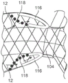
Fig. 6A and 6B illustrate a variation of the instrument with a proximal flow activated seal 116, the proximal flow activated seal 116 being located at a proximal region of the filter instrument 100, much like the distal seal. Note that the collar is shown adjacent to seal 116. However, variations of the filter apparatus 100 may include a proximal seal 116 located in any portion of the proximal portion. Any of the seal designs disclosed herein for the distal seal may also be used at the proximal location, or some combination thereof, so long as they seal against flow from the distal portion of the instrument.
Fig. 6A and 6B also illustrate a variation where the proximal seal 116 includes an appendage 118, the appendage 118 connecting the seal back to the braid. This connection prevents inversion of the seal 116. In the illustrated variation, as shown, the seal 116 is permanently affixed to the braid (i.e., adhesive bonding, thermo-mechanical encapsulation, etc.). To ensure that the opposite end of the seal is not inverted by the blood flow 12 or by withdrawing the guide catheter, the seal may additionally be tethered 118 to another region of the braid. Tethering may be achieved by tack melt (tack melt), additional encapsulation/thermal fusion, or using additional fibers or polymer or metal filaments (filament).
Another variation of the system may include an enhanced TAVR guide conduit 130 in such a way as to enhance the sealing properties of the filter. The geometric "bump" or protrusion 138 may be in the sealing area, on the OD of the guide 130. In the variation shown in fig. 6A, the protrusion 138 is shown on the exterior of the filter apparatus 100 for illustrative purposes. The protrusion 138 may be fabricated into the conduit 130. Alternatively, or in combination, the protrusion may be added to the TAVR guide catheter 108 in a sterile environment (such as a small sterile cannula). In addition, swellable coatings, such as thick hydrophilic coatings, may also achieve a similar effect of enhancing the proximal seal.
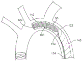
Fig. 7A-7G illustrate additional variations of the filter device 100 integrated with a system delivered from the femoral artery, through the aortic arch 2, and to the valve 10. In this variation, the filter apparatus 100 is integrated and permanently fixed to the guide catheter 140. Fig. 7A shows an example of a variation of a system with a filter instrument 100, the filter instrument 100 being integrated with a guide catheter or sheath 140 advanced to a deployment site within a vessel 2. In this variation, the filter instrument 100 is inverted within the guide sheath 140, and wherein the proximal end 120 of the instrument is attached to the distal end 142 of the guide catheter 140. As shown in fig. 7B, a stabilization instrument 170 (e.g., a dilator instrument or a support catheter) is advanced to the distal end 122 of the filter instrument 100. Fig. 7C shows the guide 140 being withdrawn while the stabilization instrument 170 stabilizes the condition of the filter instrument 100 such that the filter instrument 100 flips into place when the guide sheath 140 is withdrawn. The stabilization instrument 170 may also be used to ensure that the filter is fully restored to the open or deployed shape by extending it through the filter instrument 100. Fig. 7C shows the distal portion 122 of the instrument 100 with a flow activated seal and the proximal portion 120 of the instrument 100 coupled to the distal end 142 of the guide catheter 140.
The use of the stabilization instrument 170 allows the filter to be "squeezed out" by pushing the filter 100 distally using the stabilizer/dilator 170. Alternatively, the stabilizer/dilator 170 may advance an inverted filter at the proximal end to stabilize the filter, and then the outer sheath of the restraining sheath may be withdrawn proximally to untwist the filter.
Next, as shown in fig. 7D, the TAVR implant 132 and system 130 are advanced through a guide catheter or sheath 140 with the integrated filter instrument 100. The distal end 120 of the filter 100 contains the flow activated seal 102. Fig. 7E illustrates TAVR implant 132 deployed at a deployment site with emboli 30 in the flowing blood, but directed into filter apparatus 100 due to flow activated seal 102. Since the proximal end is integrated with the distal end 142 of the guide catheter 140, there is no risk of emboli escaping through the proximal end 120 of the instrument 100.
Fig. 7F illustrates closing the distal end 122 of the filter instrument 100 using one or more pull wires 124. As illustrated, the embolic particles 30 are secured within a closed filter instrument 100, which filter instrument 100 is integrated with/secured to a guide catheter 140. Fig. 7G illustrates an optional feature of the system, wherein the filter instrument 100 may be flipped back into the guide catheter 140. As shown, the pull wire 124 is tensioned to bring the distal portion 122 of the closed filter instrument 100 back into the catheter body 140, which causes the filter instrument 100 to evert into the guide body 140. Also, since the filter is closed, there is no risk of losing the captured emboli. Such a step may ensure that the filter and emboli are protected during removal from the body.
It should also be noted that additional design options include building the filter onto the femoral introducer sheath (i.e., a long sheath with the filter located near the aortic valve) or using a long sheath to constrain the filter if the filter is not pre-inverted in the guide catheter.
Fig. 8A to 8E show another variant of a filter device directly incorporated in a surgical device. For example, the filter apparatus may be built directly into the TAVR guide catheter, thus eliminating the need for an additional guide catheter for the filter alone. Fig. 8A illustrates a TAVR guide catheter 130 for advancing a TAVR implant 132 to the site of the valve 2 within the aorta 2. Fig. 8A does not show the filter, but the filter is loaded inside the TAVR guide catheter 130.
Fig. 8B shows the filter instrument 100 delivered from the TAVR guide catheter 130. Such deployment may be accomplished in any manner disclosed herein (inverted inside the guide catheter and delivered by "pushing" with another integrated tube or the like; or simply squeezing inside the TAVR guide catheter and unsheathing the sheath). Fig. 8C shows the TAVR balloon and guide wire removed from the site. Because the filter instrument 100 is mechanically integrated with the catheter body 130, there is no concern that emboli may escape through the proximal region of the filter instrument 100. Fig. 8D illustrates one or more guide wires 124 for closing the distal end 122 of the filter instrument 100. The proximal end of the filter instrument 100 is positioned within the distal end 128 of the TAVR guide catheter 130. Fig. 8E shows a variation in which the filter instrument 100 is coupled to be slidable within the TAVR guide catheter 130, which allows the closed filter to be brought back into the guide catheter lumen while being removed.
The variations shown in fig. 7A-7G and 8A-8E are delivery guide catheters that may be configured as TAVR systems or systems configured as separate delivery catheters.
Fig. 9A-9C illustrate additional configurations for restraining the filter apparatus 100. In the example shown in fig. 9A, filter apparatus 100 includes a double layer web layer having an inner web 108 and an outer web 109. In one example, the mesh layers 108, 109 comprise nitinol braids. An additional ring structure 160 is provided at the end of the filter apparatus 100. In the illustrated example, the ring structure 160 comprises a coil shape. However, alternative shapes (e.g., straight wire, sinusoidal, spiral, etc.) may be used, so long as the shape provides an outward radial force to hold the ends of the filter 100 in the open configuration. One or more pull wires 156 are coupled to the ring 160 such that a force exerted on the pull wires 156 closes the ring 160 and the ends of the filter instrument 100. The illustrated example shows the pull wire 156 extending through a tube (e.g., a polyimide tube). Fig. 9B shows the loop structure 160 coupled with the pull wire 156 without the mesh of the filter instrument. As described above, the coiled loop 160 provides an outward radial force that opens the end of the filter apparatus when unconstrained. Applying force 52 on wire 156 away from loop 160 results in closure 52 of loop 160 and the filter instrument.
Fig. 9C shows another variant of the self-expanding ring 164. In this variation, the loop is wave-shaped with pull wire 158 passing through loop 164. As described above, the loop 164 is self-expanding (or heat activated) to provide an outward expanding force on the filter instrument 100. Pull wire 158 is used to close loop 164 and filter instrument 100 when a closing force is applied. Pull wire 158 may optionally pass through tube 162, or may be incorporated into the mesh of the filter.
Note that any of the ring designs discussed herein may be used interchangeably for the distal and/or proximal regions of the filter, or any combination thereof. Furthermore, the ring design may be incorporated at any intermediate portion of the filter, if desired.
Fig. 10A-10C illustrate the opening of the filter apparatus 100 controlled using one or more balloons. For example, fig. 10A illustrates a variation of filter instrument 100 having an elastomeric balloon 180 at the end of filter instrument 100. In this variation, the balloon is in the closed position (as shown) when unpressurized. Application of fluid through line 184 causes balloon 180 to expand 188 to open filter apparatus 100. Fig. 10B illustrates another variation of filter instrument 100 with balloon 182 in a normally open position. Application of fluid through line 184 causes balloon 182 to collapse inwardly as shown in fig. 10C.
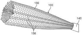
Fig. 11A-11C illustrate further variations of filter instruments that utilize the lasso effect to close the ends of the filter. Likewise, all of the closure mechanisms discussed herein may be applied to the proximal, distal, and/or intermediate portions of the filter instrument. Fig. 11A shows a pull wire 156 for forming an aperture or opening at the end of the filter instrument 100 that can be restricted/closed by pulling the wire 156. The pull wire 156 reduces the diameter of the filter apparatus 100 and effectively closes the attachment portion of the filter 100. In this variation, the wire 156 is located at the distal end of the guide catheter 140 with an integrated filter instrument. However, such a closure structure may be used on any filter apparatus. Furthermore, these concepts may be equally applicable to the proximal end of the filter.
As noted above, some applications of the instrument require a closure mechanism to completely and sufficiently close the open end of the filter in order to prevent emboli from spreading. In such applications, the wire 156 may be constructed of superelastic nitinol wire with an oxide coating (about 0.001 "to 0.002"), but the deformation of the instrument allows the oxide coating to be as thick as 0.010 ". The wire may also be ribbon wire, rectangular or other shape. Fibers or polymers or threads are also optional. Fig. 11B shows two sets of pull wires 156 coupled to the distal end of the filter instrument 100. Fig. 11C shows sets of pull wires 156 closing the ends of the filter instrument.
Fig. 12A-12C illustrate another variation of the filter instrument 100 integrated with a guide catheter 140 and constrained within an outer sheath 190. Figure 12A shows the filter instrument 100 and guide catheter 140 constrained within the outer sheath 190 such that the system can be advanced to a deployment site as discussed herein. This variant is typically delivered from the femoral artery where the TAVR system is delivered. Fig. 12B shows the outer restraining sheath 190 withdrawn 192 while the guide catheter 140 remains stationary. Withdrawal of the restraining sheath 190 causes the filter instrument 100 to expand. As mentioned above, the flow activated seal will ensure proper filtration of the blood vessel. This is a dual catheter design or coaxial system where one catheter 140 is integrated with the filter apparatus 100 and one catheter/sheath 190 is used to constrain the filter 100 for delivery. Variations of this system include replacing the outer sheath 190 with another mechanism, such as a coil or short collar, to restrain the filter. In further variations, the outer sheath 190 may be very thin, such as a polyimide tube reinforced with a coil, in which case it is only intended to constrain the filter and does not need to navigate on its own. Fig. 12C shows activation of the pull wire 156 after the procedure is completed. Activation of the pull wire closes the end of the filter instrument 100 to secure any embolic particles within the filter 100.
Fig. 13A-13C illustrate a variation of a filter body for use with the apparatus described herein. Fig. 13A shows a dual layer filter apparatus 100 in which the outer layer comprises a mesh 108 or thin film porous material, such as a polymer film with pores or pores (e.g., laser drilled, chemically formed, mechanically formed), and the inner layer comprises a coil or braid 148, the coil or braid 148 designed to provide a radial force such that the filter body 100 opens with the radial force to contact the wall of the blood vessel. Fig. 13B and 13C illustrate non-expanded and expanded filter apparatus 100, respectively, including inner expansion member 150 with mesh or braid 108. The coiled expansion member 150 opens and opens the braid when expanded. It should also be noted that the filter apparatus 100 may be made from components other than wire braid or mesh. For example, the filter apparatus 100 may include a porous polymer membrane, such as polyurethane or similar material. The porosity of the film may be achieved by laser machining, chemical etching or other chemical treatment, or micro-milling processes, or other means known to those skilled in the art. In another variation, the filter apparatus is constructed from a membrane process. Films such as thin film metals can be made with custom selected porosities. The filter shown in fig. 13A-13C provides multiple layers, with an inner layer (e.g., coils, braid, stent-like structure) providing an outward radial force to open the filter, and an outer layer (e.g., braid, polymer, porous membrane, porous metal membrane) providing filtration of blood.
Fig. 14A to 14E show another variant of a filter device with a multilayer seal. In this variation, as shown in fig. 14A, the mesh 108 of the filter apparatus 100 terminates in a series of petals 105, 107. The configuration of the petals 105, 107 may include individual filaments or filaments from the inner/outer mesh (which return to form the outer/inner mesh). The petals may be atraumatic or may include features that increase friction with the vessel wall (or walls of the body lumen). Fig. 14B illustrates alternating petals 107 shaped with offsets 126, e.g., alternating petals 107 are shaped to extend upward 126, and then the next petal 105 may be horizontal (as shown), or even extend slightly downward (into the ID of the instrument 100), as shown in fig. 14C. This angling and separation of the petals creates a space to attach the flow activated seal 102. As shown, the seal 102 may have both an upper surface 164 and a lower surface 165. In one variation, the seal 102 may be formed from a single portion of polymer film, or may be two separate pieces that meet and overlap at an apex. It is also possible that a selectively small "hole" 163 in the seal 102 may be beneficial to control the pressure inside the seal 102 and ensure that blood flow does not overpressurize the seal 102 and dislodge the position of the filter apparatus 100. It should also be noted that this same design concept can be achieved with "standard" knits (i.e., without petals). In this case, the individual braided filaments would be formed to extend outwardly or to flatten/extend inwardly, and then the ends of the filaments would terminate within the sealing polymer. Fig. 14E illustrates a partial side view of the upper seal 164 and the lower seal 165 with a space therebetween for increasing pressure in response to blood flow. As described herein, the upper seal 164 may be configured to preferentially deflect into the wall of the vessel (e.g., by sizing or material selection).
Fig. 15 shows another variant of the filter apparatus 100. The previous variation shows the filter instrument 100 attached at or near the distal end of the guide catheter. Here, the filter 100 is attached to the outside of the guide 174. The filter 100 may be self-expanding (or mechanically assisted, as previously described) and then opened by conventional methods (release of a pull wire, activation of a coil or inflation of a lumen, or removal of an external sheath or cover). Once collection of thrombus is complete, the filter 100 can be closed to the OD of the guide/sheath 174, trapping emboli between the filter and the surface of the guide. It should be noted that guide 174 may be a surgical guide, TAVR guide, and/or a sheath. Sheath options include long introducer sheaths, surgical sheaths, and/or expandable sheaths (i.e., e-sheaths).
Fig. 16A-16C illustrate additional variations of instruments for use with the procedures described herein. Fig. 16A illustrates the distal end of the TAVR guide catheter 144, where the distal end is expanded outwardly at a plurality of points 144, presumably to maintain contact on the proximal edge of the balloon, and possibly even on a compressed TAVR valve. As shown, the guide 130 with the inverted (or non-inverted, but simply compressed) filter can still have this flared distal end. The mesh of the filter apparatus 100 may be folded into the guide catheter 130.
Fig. 16B illustrates a further variation during or after use with the filter apparatus described herein. In this example, after the filter is deployed in place (whether radial approach or femoral approach), a custom catheter or guidewire with a "brush-like" 176 attachment is advanced to the surgical site to loosen any plaque or other debris from the surgical site (e.g., valve or any other surgical site). The customized catheter 176 may be delivered to the surgical site (e.g., aortic valve 10) prior to TAVR introduction. Brush attachments are a variation of devices that can loosen debris. For example, the brush instrument may have bristles or bristle-like protrusions, such as polymer fibers, disposed about the distal end. The protrusion "knocks off (knock free)" any loose plaque from the aortic valve before placing a new filter. This may be done to simply achieve a better fit of the new valve relative to the aortic wall, or may be done to minimize the likelihood of plaque rupture release after the procedure is performed, particularly possibly after removal of the filter.
Another option is to deploy a filter (femoral approach or radial approach) as shown in fig. 16B and pre-dilate the aortic valve with a balloon catheter. The deployment of the balloon may simply allow for better fitting of the new valve relative to the aortic wall, or may be performed to minimize the likelihood of plaque rupture release after the procedure is performed. Fig. 16C shows a variant where blood is returned through a catheter 112 extending from the left subclavian artery 4 and from the radial artery. Once outside the patient's body, the blood may flow through a simple filter 196 having a similar pore size. Filters are readily available in paper, woven textile, polymer and film composites. A shrink ring or collar 104 may still be used at the proximal region to allow passage of the TAVR system. Alternatively, this design configuration may also be used on the patient after the procedure is performed to collect any newly ruptured emboli. In this case, the constricting toroid will be fully closed, forcing all blood through the conduit and filter. A portion of the filter may be made impermeable to control how much blood flows into the catheter/filter circuit and into other blood vessels. The filtered blood may be returned to the body via, for example, the femoral access point 198.
As to other details of the invention, materials and fabrication techniques may be employed at the level of those skilled in the relevant art. In terms of additional acts that may be employed generically or logically, this may apply equally in terms of the method-based aspects of the invention. Furthermore, although the present invention has been described with reference to several examples, optionally incorporating various features, the invention is not limited to what has been described or indicated as the anticipation of each variant of the invention.
Various changes may be made to the invention described and equivalents may be substituted (whether referred to herein or not for the sake of brevity) without departing from the true spirit and scope of the invention. Furthermore, any optional feature of the inventive variations may be set forth and claimed independently or in combination with any one or more of the features described herein. Thus, the present invention contemplates combinations of aspects of the embodiments or the embodiments themselves, where possible. Reference to a single item includes the possibility that a plurality of the same item exists. More specifically, as used herein and in the appended claims, the singular forms "a," "and," "said," and "the" include plural references unless the context clearly dictates otherwise.
It is important to note that aspects of the various described embodiments, or the embodiments themselves, may be combined where possible. All such combinations are intended to fall within the scope of the present disclosure.
Claims (82)
1. A protective system for reducing emboli migration within a blood stream in a blood vessel, the system comprising:
a filter body having a distal portion and a proximal portion, wherein the filter body is configured for positioning within the blood vessel such that the blood flow enters the distal portion, wherein a wall of the filter body is porous to allow the blood flow to pass therethrough while capturing emboli within the blood flow;
a sealing membrane located circumferentially on the distal portion, wherein the sealing membrane deflects from the filter body as a result of blood flow against the sealing membrane, wherein the deflection of the sealing member allows a seal to be formed against a wall of the blood vessel; and
a catheter body configured to be navigated through the blood vessel, wherein the filter body is configured to be located around an exterior of the catheter body.
2. The apparatus of claim 1, wherein the sealing membrane comprises a fluid impermeable material.
3. The apparatus of claim 1, wherein the sealing membrane includes an expandable portion such that blood flow against the sealing membrane causes the expandable portion to expand.
4. The filter apparatus of claim 1, wherein the sealing membrane comprises a thin film polymer or elastomer.
5. The filter apparatus of claim 1, wherein the sealing membrane is located within the filter body.
6. The filter apparatus of claim 1, wherein the sealing membrane is located on an inner diameter of the filter body and further comprising a second sealing membrane located on an exterior of the filter body, wherein blood flow causes the sealing membrane to deflect to increase an effective sealing area of the filter apparatus.
7. The filter apparatus of claim 1, wherein the sealing membrane includes a first layer and a second layer, wherein the first layer is adjacent an outer surface of the filter apparatus and the second layer is adjacent an interior channel of the filter apparatus.
8. The filter apparatus of claim 7, wherein the first layer is connected to the second layer such that blood flow into a region of the sealing membrane bounded by the first layer and the second layer increases pressure to further enhance opening of the sealing membrane.
9. The filter apparatus of claim 7, wherein the first layer is configured to expand more than the second layer such that the sealing membrane expands outward from the filter apparatus.
10. The filter apparatus of claim 1, further comprising a series of petals on a distal end of the filter body, wherein the sealing membrane is coupled to the series of petals.
11. The filter apparatus of claim 10, wherein the series of petals includes at least one deflected petal, and wherein the sealing membrane includes a first layer coupled to the at least one deflected petal and a second layer coupled to the series of petals such that blood flow into a region between the first layer and the second layer increases pressure in the region.
12. The apparatus of claim 1, wherein the filter body comprises a mesh braid.
13. The filter instrument of claim 12, wherein the mesh braid comprises superelastic nitinol.
14. The filter apparatus of claim 1, wherein the filter body comprises a thin film polymer or elastomer.
15. The apparatus of claim 1, wherein the filter body has a pore size of 40-200 microns.
16. The apparatus of claim 1, wherein the sealing member further expands in response to blood flow.
17. The instrument of claim 1, further comprising a proximal sealing membrane positioned within the filter body and adjacent to the proximal portion of the instrument.
18. The filter apparatus of claim 1, wherein the filter body comprises a sheet of material having a controlled porosity.
19. The apparatus of claim 1, wherein the filter body is comprised of strips of material that overlap to form a continuous surface.
20. The apparatus of claim 1, further comprising at least one pull wire coupled to the distal end such that an applied tension on the pull wire advances the distal end to a closed position.
21. The apparatus of claim 20, further comprising at least one resilient ring at a distal end of the filter body to bias the distal end in an open position in the absence of the tensioning force.
22. A protective system for reducing emboli migration within a blood stream in a blood vessel, the system comprising:
a filter body having a distal portion and a proximal portion, wherein the filter body is configured for positioning within the blood vessel such that the blood flow enters the distal portion, wherein a wall of the filter body is porous to allow the blood flow to pass therethrough while capturing emboli within the blood flow;
a sealing membrane located circumferentially on the distal portion, wherein the sealing membrane deflects from the filter body as a result of blood flow against the sealing membrane, wherein the deflection of the sealing member allows a seal to be formed against a wall of the blood vessel; and
a catheter body configured to be navigated through the blood vessel, wherein the filter body is configured to re-enter the catheter body such that the filter body and emboli located therein are protected within a sheath body when removed from a patient.
23. The apparatus of claim 22, further comprising a synchronization member configured to synchronize a portion of the filter body.
24. The apparatus of claim 22, wherein the sealing membrane comprises a fluid impermeable material.
25. The apparatus of claim 22, wherein the sealing membrane includes an expandable portion such that blood flow against the sealing membrane causes the expandable portion to expand.
26. The filter apparatus of claim 22, wherein the sealing membrane comprises a thin film polymer or elastomer.
27. The filter apparatus of claim 22, wherein the sealing membrane is located within the filter body.
28. The filter apparatus of claim 22 wherein the sealing membrane is located on an inner diameter of the filter body and further comprising a second sealing membrane located on an exterior of the filter body, wherein blood flow causes the sealing membrane to deflect to increase an effective sealing area of the filter apparatus.
29. The filter apparatus of claim 22, wherein the sealing membrane includes a first layer and a second layer, wherein the first layer is adjacent an outer surface of the filter apparatus and the second layer is adjacent an interior channel of the filter apparatus.
30. The filter apparatus of claim 29, wherein the first layer is connected to the second layer such that blood flow into a region of the sealing membrane bounded by the first layer and the second layer increases pressure to further enhance opening of the sealing membrane.
31. The filter apparatus of claim 29, wherein the first layer is configured to expand more than the second layer such that the sealing membrane expands outward from the filter apparatus.
32. The filter apparatus of claim 22, further comprising a series of petals on a distal end of the filter body, wherein the sealing membrane is coupled to the series of petals.
33. The filter apparatus of claim 32, wherein the series of petals includes at least one deflected petal, and wherein the sealing membrane includes a first layer coupled to the at least one deflected petal and a second layer coupled to the series of petals such that blood flow into a region between the first layer and the second layer increases pressure in the region.
34. The apparatus of claim 22, wherein the filter body comprises a mesh braid.
35. The filter instrument of claim 34, wherein the mesh braid comprises superelastic nitinol.
36. The filter apparatus of claim 22, wherein the filter body comprises a thin film polymer or elastomer.
37. The apparatus of claim 22, wherein the filter body has a pore size of 40-200 microns.
38. The apparatus of claim 22, wherein the sealing member further expands in response to blood flow.
39. The instrument of claim 22, further comprising a proximal sealing membrane positioned within the filter body and adjacent to the proximal portion of the instrument.
40. The filter apparatus of claim 22, wherein the filter body comprises a sheet of material having a controlled porosity.
41. The apparatus of claim 22, wherein the filter body is comprised of strips of material that overlap to form a continuous surface.
42. The apparatus of claim 22, further comprising at least one pull wire coupled to the distal end such that an applied tension on the pull wire advances the distal end to a closed position.
43. The instrument of claim 42, further comprising at least one resilient ring located at a distal end of the filter body to bias the distal end in an open position in the absence of the tensioning force.
44. The apparatus of claim 22, wherein the catheter body comprises a TAVR guide catheter.
45. The instrument of claim 22, wherein a proximal portion of the filter body is attached to a distal portion of the catheter body.
46. The instrument of claim 22, wherein, in a deployed configuration, the filter body is inverted within the catheter body such that the distal portion of the filter body is proximal to the proximal portion of the filter body within the catheter body.
47. The instrument of claim 46, further comprising a stabilization instrument positioned within the catheter body, wherein the stabilization instrument is configured to support the distal portion of the filter body when the catheter body is withdrawn relative to the filter body such that withdrawal of the catheter body causes the filter body to evert from the distal end of the catheter body.
48. A method for filtering emboli dislodged during a procedure performed within the vasculature of a patient from a blood vessel, the method comprising:
positioning a filter instrument at a deployment site in the vessel, wherein the deployment site is downstream of the surgical site, a distal portion of the filter instrument comprising a sealing member;
deploying the filter instrument such that blood flow to the filter instrument causes the sealing member to form a seal against a wall of the blood vessel, and wherein a body of the filter instrument allows the blood flow to pass while restricting flow of emboli such that emboli within the blood flow remain within the filter instrument;
securing the filter instrument and emboli located therein within a catheter body after the procedure; and
removing the catheter body, the filter instrument, and emboli from the blood vessel.
49. The method of claim 48, wherein deploying the filter instrument further comprises advancing a second catheter through a proximal opening of the filter instrument and retracting a proximal portion of the filter instrument about the second catheter to prevent emboli from appearing between the second catheter and the proximal opening.
50. The method of claim 49, further comprising completing the procedure and withdrawing the second catheter from the filter instrument while simultaneously retracting the proximal portion of the filter instrument about the second catheter, and further retracting the filter instrument to prevent emboli from escaping from the proximal opening when the second catheter is removed from the filter instrument.
51. The method of claim 50, wherein securing the filter instrument and emboli located therein includes withdrawing the filter instrument into the catheter body.
52. The method of claim 51, further comprising restricting a distal opening of the filter instrument prior to withdrawing the filter instrument into the catheter body.
53. The method of claim 50, wherein the filter instrument includes a proximal seal member, wherein the blood flow causes the proximal seal member to form a proximal seal against the second catheter.
54. The method of claim 48, wherein the filter instrument is attached to the distal end of the catheter body.
55. The method of claim 54 wherein the filter instrument is inverted within the catheter body prior to deploying the filter instrument, and wherein deploying the filter instrument comprises securing a proximal end of the filter instrument within the catheter body while withdrawing the catheter body relative to the filter instrument such that the filter instrument is inverted into place within the blood vessel.
56. The method of claim 54, wherein the filter instrument is inverted within the catheter body prior to deploying the filter instrument, and wherein deploying the filter instrument comprises pushing a proximal end of the filter instrument out of the catheter body such that the filter instrument is flipped into place within the blood vessel.
57. The method of claim 54, further comprising advancing a second catheter through the catheter body and the filter instrument to perform the procedure.
58. The method of claim 54, further comprising restraining a distal end of the filter body to prevent emboli from passing through the distal end.
59. The method of claim 58, further comprising withdrawing the distal end of the filter body into the catheter body such that the filter body everts within the catheter body.
60. The method of claim 48, wherein after deploying the filter instrument, emboli are loosened from the surgical site using a balloon catheter or a brush instrument in order to ensure capture of emboli within the filter body.
61. The method of claim 48, wherein the filter instrument is positioned in the aorta.
62. The method of claim 48, wherein positioning the filter instrument at the deployment site in the vessel comprises advancing the filter instrument and the catheter body through a radial vessel.
63. The method of claim 48, wherein positioning the filter instrument at the deployment site in the vessel comprises advancing the filter instrument and the catheter body through a femoral vessel.
64. The method of claim 48, further comprising passing a portion of the blood flow outside the patient's body through an external filter and returning the blood flow to the patient's artery.
65. A method for filtering emboli dislodged at a surgical site within a vessel of a patient during a medical procedure, the method comprising:
advancing a filter instrument to a deployment site in the vessel, wherein a distal portion of the filter instrument comprises a sealing member;
deploying the filter instrument near the surgical site, wherein the filter instrument allows blood to pass through;
forming a first seal between walls of the blood vessel at the deployment site using the sealing member, thereby causing blood to flow into the filter apparatus;
advancing a medical instrument through the filter instrument to the surgical site;
performing a procedure in the blood vessel distal to the filter instrument using the medical instrument, wherein the procedure results in an embolus entering the blood stream;
withdrawing the medical device from the deployment site and further constraining the proximal portion of the filter device such that emboli remain within the filter device;
positioning the filter apparatus and emboli located therein within a catheter to prevent emboli from entering the blood stream; and
removing the catheter, the filter instrument, and emboli from the patient.
66. The method of claim 65, further comprising, after advancing the medical instrument through the filter instrument, retracting a proximal portion of the filter instrument about the medical instrument to form a second seal about the medical instrument.
67. The method of claim 65, wherein deploying the filter instrument further comprises advancing a second catheter through a proximal opening of the filter instrument and retracting a proximal portion of the filter instrument around the second catheter to prevent emboli from appearing between the second catheter and the proximal opening.
68. The method of claim 67, further comprising completing the procedure and withdrawing the second catheter from the filter instrument while simultaneously retracting the proximal portion of the filter instrument around the second catheter and, upon removal of the second catheter from the filter instrument, further retracting the filter instrument to prevent emboli from escaping from the proximal opening.
69. The method of claim 68, wherein securing the filter instrument and emboli located therein includes withdrawing the filter instrument into the catheter body.
70. The method of claim 69, further comprising restricting a distal opening of the filter instrument prior to withdrawing the filter instrument into the catheter body.
71. The method of claim 68, wherein the filter instrument includes a proximal seal member, wherein the blood flow causes the proximal seal member to form a proximal seal against the second catheter.
72. The method of claim 65, wherein the filter instrument is attached to the distal end of the catheter body.
73. The method of claim 72, wherein the filter instrument is inverted within the catheter body prior to deploying the filter instrument, and wherein deploying the filter instrument comprises securing a proximal end of the filter instrument within the catheter body while withdrawing the catheter body relative to the filter instrument such that the filter instrument is inverted into place within the blood vessel.
74. The method of claim 72, wherein the filter instrument is inverted within the catheter body prior to deploying the filter instrument, and wherein deploying the filter instrument comprises pushing a proximal end of the filter instrument out of the catheter body such that the filter instrument is flipped into place within the blood vessel.
75. The method of claim 72, further comprising advancing a second catheter through the catheter body and the filter instrument to perform the procedure.
76. The method of claim 72, further comprising restraining a distal end of the filter body to prevent emboli from passing through the distal end.
77. The method of claim 76, further comprising withdrawing the distal end of the filter body into the catheter body such that the filter body everts within the catheter body.
78. The method of claim 65, wherein after deployment of the filter instrument, emboli are loosened from the surgical site using a balloon catheter or a brush instrument in order to ensure capture of emboli within the filter body.
79. The method of claim 65, wherein the filter instrument is positioned in the aorta.
80. The method of claim 65, wherein positioning the filter instrument at the deployment site in the vessel comprises advancing the filter instrument and the catheter body through a radial vessel.
81. The method of claim 65, wherein positioning the filter instrument at the deployment site in the vessel comprises advancing the filter instrument and the catheter body through a femoral vessel.
82. The method of claim 65, further comprising passing a portion of the blood flow outside the patient's body through an external filter and returning the blood flow to the patient's artery.
Priority Applications (1)
| Application Number | Priority Date | Filing Date | Title |
|---|---|---|---|
| CN202211129969.XA CN115475029A (en) | 2018-03-27 | 2019-03-27 | Auxiliary instrument for providing neuroprotection during interventional procedure |
Applications Claiming Priority (3)
| Application Number | Priority Date | Filing Date | Title |
|---|---|---|---|
| US201862648393P | 2018-03-27 | 2018-03-27 | |
| US62/648,393 | 2018-03-27 | ||
| PCT/US2019/024356 WO2019191281A1 (en) | 2018-03-27 | 2019-03-27 | Accessory device to provide neuroprotection during interventional procedures |
Related Child Applications (1)
| Application Number | Title | Priority Date | Filing Date |
|---|---|---|---|
| CN202211129969.XA Division CN115475029A (en) | 2018-03-27 | 2019-03-27 | Auxiliary instrument for providing neuroprotection during interventional procedure |
Publications (1)
| Publication Number | Publication Date |
|---|---|
| CN112423703A true CN112423703A (en) | 2021-02-26 |
Family
ID=68060745
Family Applications (2)
| Application Number | Title | Priority Date | Filing Date |
|---|---|---|---|
| CN201980035636.0A Pending CN112423703A (en) | 2018-03-27 | 2019-03-27 | Auxiliary instrument for providing neuroprotection during interventional procedure |
| CN202211129969.XA Pending CN115475029A (en) | 2018-03-27 | 2019-03-27 | Auxiliary instrument for providing neuroprotection during interventional procedure |
Family Applications After (1)
| Application Number | Title | Priority Date | Filing Date |
|---|---|---|---|
| CN202211129969.XA Pending CN115475029A (en) | 2018-03-27 | 2019-03-27 | Auxiliary instrument for providing neuroprotection during interventional procedure |
Country Status (6)
| Country | Link |
|---|---|
| US (3) | US11684465B2 (en) |
| EP (2) | EP3773329B1 (en) |
| JP (2) | JP7237997B2 (en) |
| CN (2) | CN112423703A (en) |
| ES (1) | ES2952935T3 (en) |
| WO (1) | WO2019191281A1 (en) |
Cited By (1)
| Publication number | Priority date | Publication date | Assignee | Title |
|---|---|---|---|---|
| CN113520674A (en) * | 2021-07-16 | 2021-10-22 | 湖南埃普特医疗器械有限公司 | Valve expansion protection device |
Families Citing this family (14)
| Publication number | Priority date | Publication date | Assignee | Title |
|---|---|---|---|---|
| US9345573B2 (en) | 2012-05-30 | 2016-05-24 | Neovasc Tiara Inc. | Methods and apparatus for loading a prosthesis onto a delivery system |
| EP3672530A4 (en) | 2017-08-25 | 2021-04-14 | Neovasc Tiara Inc. | Sequentially deployed transcatheter mitral valve prosthesis |
| JP7237997B2 (en) | 2018-03-27 | 2023-03-13 | マドゥロ ディスカバリー,エルエルシ― | Adjunctive devices for neuroprotection during interventional therapy |
| JP7260930B2 (en) | 2018-11-08 | 2023-04-19 | ニオバスク ティアラ インコーポレイテッド | Ventricular deployment of a transcatheter mitral valve prosthesis |
| WO2020168091A1 (en) * | 2019-02-13 | 2020-08-20 | Emboline, Inc. | Catheter with integrated embolic protection device |
| EP3946163A4 (en) | 2019-04-01 | 2022-12-21 | Neovasc Tiara Inc. | Controllably deployable prosthetic valve |
| EP3972673A4 (en) | 2019-05-20 | 2023-06-07 | Neovasc Tiara Inc. | Introducer with hemostasis mechanism |
| EP4135818A1 (en) | 2019-06-15 | 2023-02-22 | Maduro Discovery, LLC | Catheter construction |
| WO2020257643A1 (en) | 2019-06-20 | 2020-12-24 | Neovasc Tiara Inc. | Low profile prosthetic mitral valve |
| WO2021207728A1 (en) * | 2020-04-10 | 2021-10-14 | Duke University | Device for cerebral embolic protection |
| US11376028B1 (en) * | 2021-04-17 | 2022-07-05 | Inquis Medical, Inc. | Devices, systems, and methods for removing obstructive material from body lumens |
| WO2023278495A2 (en) | 2021-06-28 | 2023-01-05 | Inquis Medical, Inc. | Apparatuses and methods for controlling removal of obstructive material |
| US20240016596A1 (en) * | 2022-07-15 | 2024-01-18 | Brian B. Martin | Accessory device to provide neuroprotection during interventional procedures |
| AU2023204303B1 (en) * | 2023-05-09 | 2023-11-09 | Venus Medtech (Hangzhou) Inc. | Expandable sheath for transcatheter delivery system and delivery system |
Citations (12)
| Publication number | Priority date | Publication date | Assignee | Title |
|---|---|---|---|---|
| US6306163B1 (en) * | 1998-08-04 | 2001-10-23 | Advanced Cardiovascular Systems, Inc. | Assembly for collecting emboli and method of use |
| US6361545B1 (en) * | 1997-09-26 | 2002-03-26 | Cardeon Corporation | Perfusion filter catheter |
| US20020183783A1 (en) * | 2001-06-04 | 2002-12-05 | Shadduck John H. | Guidewire for capturing emboli in endovascular interventions |
| CN1447669A (en) * | 2000-08-18 | 2003-10-08 | 阿特里泰克公司 | Expandable implant devices for filtering blood flow from atrial appendages |
| US20040006367A1 (en) * | 2001-06-12 | 2004-01-08 | Krik Johnson | Emboli extraction catheter and vascular filter system |
| US20080167708A1 (en) * | 2006-11-17 | 2008-07-10 | Doug Molland | Stent having reduced passage of emboli and stent delivery system |
| US8206412B2 (en) * | 2008-06-23 | 2012-06-26 | Lumen Biomedical, Inc. | Embolic protection during percutaneous heart valve replacement and similar procedures |
| US20120172916A1 (en) * | 2010-12-30 | 2012-07-05 | Claret Medical, Inc. | Method of Isolating the Cerebral Circulation During a Cardiac Procedure |
| US20140277096A1 (en) * | 2013-03-14 | 2014-09-18 | Valve Medical Ltd. | Temporary valve and valve-filter |
| US20140288588A1 (en) * | 2013-03-15 | 2014-09-25 | Microvention, Inc. | Embolic Protection Device |
| US20160120636A1 (en) * | 2013-06-12 | 2016-05-05 | Keystone Heart Ltd. | Intravascular device with multiple leaflets |
| WO2017024258A1 (en) * | 2015-08-06 | 2017-02-09 | Kp Medcure, Inc. | Axially lengthening thrombus capture system |
Family Cites Families (12)
| Publication number | Priority date | Publication date | Assignee | Title |
|---|---|---|---|---|
| US7604650B2 (en) * | 2003-10-06 | 2009-10-20 | 3F Therapeutics, Inc. | Method and assembly for distal embolic protection |
| US8734479B2 (en) * | 2005-12-30 | 2014-05-27 | C.R. Bard, Inc. | Embolus blood clot filter delivery system |
| US9011467B2 (en) * | 2008-08-13 | 2015-04-21 | Silk Road Medical, Inc. | Suture delivery device |
| US8696698B2 (en) * | 2009-12-02 | 2014-04-15 | Surefire Medical, Inc. | Microvalve protection device and method of use for protection against embolization agent reflux |
| US9622846B2 (en) * | 2011-10-19 | 2017-04-18 | Don Michael International, Llc | Apparatus and procedure for trapping embolic debris |
| US9968433B2 (en) * | 2013-03-01 | 2018-05-15 | St. Jude Medical, Cardiology Division, Inc. | Embolic protection pass through tube |
| US9820852B2 (en) | 2014-01-24 | 2017-11-21 | St. Jude Medical, Cardiology Division, Inc. | Stationary intra-annular halo designs for paravalvular leak (PVL) reduction—active channel filling cuff designs |
| US9974650B2 (en) | 2015-07-14 | 2018-05-22 | Edwards Lifesciences Corporation | Prosthetic heart valve |
| US10617509B2 (en) * | 2015-12-29 | 2020-04-14 | Emboline, Inc. | Multi-access intraprocedural embolic protection device |
| US10188500B2 (en) | 2016-02-12 | 2019-01-29 | Medtronic Vascular, Inc. | Stent graft with external scaffolding and method |
| US20190336264A1 (en) * | 2016-12-01 | 2019-11-07 | Mayo Foundation For Medical Education And Research | Percutaneously-deployable intravascular embolic protection devices and methods |
| JP7237997B2 (en) | 2018-03-27 | 2023-03-13 | マドゥロ ディスカバリー,エルエルシ― | Adjunctive devices for neuroprotection during interventional therapy |
-
2019
- 2019-03-27 JP JP2020573574A patent/JP7237997B2/en active Active
- 2019-03-27 EP EP19778385.5A patent/EP3773329B1/en active Active
- 2019-03-27 ES ES19778385T patent/ES2952935T3/en active Active
- 2019-03-27 WO PCT/US2019/024356 patent/WO2019191281A1/en unknown
- 2019-03-27 US US16/366,696 patent/US11684465B2/en active Active
- 2019-03-27 CN CN201980035636.0A patent/CN112423703A/en active Pending
- 2019-03-27 CN CN202211129969.XA patent/CN115475029A/en active Pending
- 2019-03-27 EP EP23173583.8A patent/EP4218669A1/en active Pending
-
2020
- 2020-10-15 US US17/071,500 patent/US11020211B2/en active Active
-
2023
- 2023-03-01 JP JP2023031443A patent/JP2023060070A/en active Pending
- 2023-05-11 US US18/316,045 patent/US20230277290A1/en active Pending
Patent Citations (12)
| Publication number | Priority date | Publication date | Assignee | Title |
|---|---|---|---|---|
| US6361545B1 (en) * | 1997-09-26 | 2002-03-26 | Cardeon Corporation | Perfusion filter catheter |
| US6306163B1 (en) * | 1998-08-04 | 2001-10-23 | Advanced Cardiovascular Systems, Inc. | Assembly for collecting emboli and method of use |
| CN1447669A (en) * | 2000-08-18 | 2003-10-08 | 阿特里泰克公司 | Expandable implant devices for filtering blood flow from atrial appendages |
| US20020183783A1 (en) * | 2001-06-04 | 2002-12-05 | Shadduck John H. | Guidewire for capturing emboli in endovascular interventions |
| US20040006367A1 (en) * | 2001-06-12 | 2004-01-08 | Krik Johnson | Emboli extraction catheter and vascular filter system |
| US20080167708A1 (en) * | 2006-11-17 | 2008-07-10 | Doug Molland | Stent having reduced passage of emboli and stent delivery system |
| US8206412B2 (en) * | 2008-06-23 | 2012-06-26 | Lumen Biomedical, Inc. | Embolic protection during percutaneous heart valve replacement and similar procedures |
| US20120172916A1 (en) * | 2010-12-30 | 2012-07-05 | Claret Medical, Inc. | Method of Isolating the Cerebral Circulation During a Cardiac Procedure |
| US20140277096A1 (en) * | 2013-03-14 | 2014-09-18 | Valve Medical Ltd. | Temporary valve and valve-filter |
| US20140288588A1 (en) * | 2013-03-15 | 2014-09-25 | Microvention, Inc. | Embolic Protection Device |
| US20160120636A1 (en) * | 2013-06-12 | 2016-05-05 | Keystone Heart Ltd. | Intravascular device with multiple leaflets |
| WO2017024258A1 (en) * | 2015-08-06 | 2017-02-09 | Kp Medcure, Inc. | Axially lengthening thrombus capture system |
Cited By (1)
| Publication number | Priority date | Publication date | Assignee | Title |
|---|---|---|---|---|
| CN113520674A (en) * | 2021-07-16 | 2021-10-22 | 湖南埃普特医疗器械有限公司 | Valve expansion protection device |
Also Published As
| Publication number | Publication date |
|---|---|
| WO2019191281A1 (en) | 2019-10-03 |
| JP7237997B2 (en) | 2023-03-13 |
| US11020211B2 (en) | 2021-06-01 |
| ES2952935T3 (en) | 2023-11-07 |
| EP3773329A1 (en) | 2021-02-17 |
| EP3773329A4 (en) | 2021-12-08 |
| EP4218669A1 (en) | 2023-08-02 |
| CN115475029A (en) | 2022-12-16 |
| EP3773329B1 (en) | 2023-05-17 |
| JP2022515690A (en) | 2022-02-22 |
| US11684465B2 (en) | 2023-06-27 |
| US20200054432A1 (en) | 2020-02-20 |
| US20230277290A1 (en) | 2023-09-07 |
| US20210022845A1 (en) | 2021-01-28 |
| JP2023060070A (en) | 2023-04-27 |
Similar Documents
| Publication | Publication Date | Title |
|---|---|---|
| US11020211B2 (en) | Accessory device to provide neuroprotection during interventional procedures | |
| EP2822502B1 (en) | Distal protection filter | |
| US6676682B1 (en) | Percutaneous catheter and guidewire having filter and medical device deployment capabilities | |
| EP2361590B1 (en) | Vascular protection devices and methods of use | |
| US9089406B2 (en) | Embolic filter devices, systems, and methods for capturing emboli during medical procedures | |
| US20130253570A1 (en) | Apparatus and methods for filtering emboli during precutaneous aortic valve replacement and repair procedures with filtration system coupled to distal end of sheath | |
| US20060129180A1 (en) | Methods of protecting a patient from embolization during surgery | |
| US20140074148A1 (en) | Embolic protection system and method for use in an aortic arch | |
| WO2013142201A1 (en) | Apparatus and methods for filtering emboli during percutaneous aortic valve replacement and repair procedures with filtration system coupled in-situ to distal end of sheath | |
| US11304792B2 (en) | Catheter with integrated embolic protection device | |
| US20190223995A1 (en) | Device for delivery and retrieval of protection filters | |
| US11351023B2 (en) | Systems and methods for protecting the cerebral vasculature | |
| US20240016596A1 (en) | Accessory device to provide neuroprotection during interventional procedures | |
| WO2013126618A1 (en) | Embolic protection system and method for use in an aortic arch |
Legal Events
| Date | Code | Title | Description |
|---|---|---|---|
| PB01 | Publication | ||
| PB01 | Publication | ||
| SE01 | Entry into force of request for substantive examination | ||
| SE01 | Entry into force of request for substantive examination | ||
| REG | Reference to a national code |
Ref country code: HK Ref legal event code: DE Ref document number: 40046068 Country of ref document: HK |
|
| AD01 | Patent right deemed abandoned | ||
| AD01 | Patent right deemed abandoned |
Effective date of abandoning: 20230228 |