CN112421164B - Battery module fast assembly and quick heat radiation structure - Google Patents
Battery module fast assembly and quick heat radiation structure Download PDFInfo
- Publication number
- CN112421164B CN112421164B CN202011291740.7A CN202011291740A CN112421164B CN 112421164 B CN112421164 B CN 112421164B CN 202011291740 A CN202011291740 A CN 202011291740A CN 112421164 B CN112421164 B CN 112421164B
- Authority
- CN
- China
- Prior art keywords
- electrode
- heat dissipation
- battery
- heat
- liquid cooling
- Prior art date
- Legal status (The legal status is an assumption and is not a legal conclusion. Google has not performed a legal analysis and makes no representation as to the accuracy of the status listed.)
- Active
Links
Images


Classifications
-
- A—HUMAN NECESSITIES
- A62—LIFE-SAVING; FIRE-FIGHTING
- A62C—FIRE-FIGHTING
- A62C3/00—Fire prevention, containment or extinguishing specially adapted for particular objects or places
- A62C3/16—Fire prevention, containment or extinguishing specially adapted for particular objects or places in electrical installations, e.g. cableways
-
- H—ELECTRICITY
- H01—ELECTRIC ELEMENTS
- H01M—PROCESSES OR MEANS, e.g. BATTERIES, FOR THE DIRECT CONVERSION OF CHEMICAL ENERGY INTO ELECTRICAL ENERGY
- H01M10/00—Secondary cells; Manufacture thereof
- H01M10/60—Heating or cooling; Temperature control
- H01M10/61—Types of temperature control
- H01M10/613—Cooling or keeping cold
-
- H—ELECTRICITY
- H01—ELECTRIC ELEMENTS
- H01M—PROCESSES OR MEANS, e.g. BATTERIES, FOR THE DIRECT CONVERSION OF CHEMICAL ENERGY INTO ELECTRICAL ENERGY
- H01M10/00—Secondary cells; Manufacture thereof
- H01M10/60—Heating or cooling; Temperature control
- H01M10/62—Heating or cooling; Temperature control specially adapted for specific applications
- H01M10/625—Vehicles
-
- H—ELECTRICITY
- H01—ELECTRIC ELEMENTS
- H01M—PROCESSES OR MEANS, e.g. BATTERIES, FOR THE DIRECT CONVERSION OF CHEMICAL ENERGY INTO ELECTRICAL ENERGY
- H01M4/00—Electrodes
- H01M4/02—Electrodes composed of, or comprising, active material
- H01M4/64—Carriers or collectors
- H01M4/66—Selection of materials
- H01M4/665—Composites
-
- Y—GENERAL TAGGING OF NEW TECHNOLOGICAL DEVELOPMENTS; GENERAL TAGGING OF CROSS-SECTIONAL TECHNOLOGIES SPANNING OVER SEVERAL SECTIONS OF THE IPC; TECHNICAL SUBJECTS COVERED BY FORMER USPC CROSS-REFERENCE ART COLLECTIONS [XRACs] AND DIGESTS
- Y02—TECHNOLOGIES OR APPLICATIONS FOR MITIGATION OR ADAPTATION AGAINST CLIMATE CHANGE
- Y02E—REDUCTION OF GREENHOUSE GAS [GHG] EMISSIONS, RELATED TO ENERGY GENERATION, TRANSMISSION OR DISTRIBUTION
- Y02E60/00—Enabling technologies; Technologies with a potential or indirect contribution to GHG emissions mitigation
- Y02E60/10—Energy storage using batteries
Landscapes
- Chemical & Material Sciences (AREA)
- Engineering & Computer Science (AREA)
- Chemical Kinetics & Catalysis (AREA)
- Electrochemistry (AREA)
- General Chemical & Material Sciences (AREA)
- Manufacturing & Machinery (AREA)
- Health & Medical Sciences (AREA)
- Public Health (AREA)
- Business, Economics & Management (AREA)
- Emergency Management (AREA)
- Composite Materials (AREA)
- Materials Engineering (AREA)
- Secondary Cells (AREA)
- Battery Mounting, Suspending (AREA)
- Connection Of Batteries Or Terminals (AREA)
Abstract
The invention discloses a quick assembly and quick heat dissipation structure of a battery module, which comprises a battery shell, a bus bar, a heat dissipation assembly and a plurality of single batteries, wherein an electrode structure of each single battery comprises an electrode head, a flexible conductive part and an electrode sleeve, the electrode sleeve is sleeved outside the electrode head, one end of the electrode head is exposed out of the electrode sleeve and is connected with an electrode jack of the bus bar in an inserting mode, the other end of the electrode head is welded and fixed with an electrode splicing piece of each single battery through the flexible conductive part, a protruding part is arranged at the bottom of one side of the bus bar, which is provided with the electrode jack, the lower part of the electrode sleeve is fixedly clamped with the protruding part through an I-shaped fixing plug inserted into the side face, an electrode heat dissipation part which is contacted with the electrode sleeve and the protruding part from the side face is arranged on the upper side of the heat dissipation part of the heat dissipation assembly, and the electrode heat dissipation part blocks the I-shaped fixing plug after the electrode structure is connected. The invention can make the battery assembling process simpler and more convenient on the premise of ensuring the safety and reliability of the battery electrode connection part, and is convenient for later disassembly and maintenance.
Description
Technical Field
The invention belongs to the technical field of batteries, and relates to a quick assembly and quick heat dissipation structure of a battery module.
Background
In fields such as new energy automobile, the battery module that adopts polylith battery series-parallel connection to form supplies power in order to guarantee the demand of voltage and electric quantity usually, and connect reliably in order to guarantee the joint position, avoid the pine to take off and generate heat and burn out, battery module series-parallel connection is generally through the bolt, soldering or laser welding connect, wherein adopt bolted connection to cause the battery short circuit easily, and the battery module in the battery module is more in quantity, this scheme needs too many bolts, greatly increased module weight, adopt the welded connection mode, it is the battery part that receives the heat altered shape easily to be high temperature in welding process, be difficult to dismantle the maintenance simultaneously, the soldering needs more energy simultaneously, and the production process is loaded down with trivial details. Therefore, the assembly structure of the battery module in the prior art has the defects of inconvenient assembly, long time consumption and difficult follow-up disassembly and maintenance.
The connector interface connection mode of the conventional plug-in structure also has other problems in application and battery modules, although the plug-in mode saves time and labor in installation and disassembly maintenance, the plug-in structure is easily loosened due to vibration, the shockproof loosening effect must be considered in the fields of application, new energy automobiles and the like, the connector part is loosened to easily cause poor contact, resistance is increased to seriously heat the connector part, and the safety of the battery is seriously influenced. General interference fit plug-in is easy to be unsuitable because of vibration loosening, even a joint part which is plugged from the side rear part by adopting an elastic structure is easy to have problems, firstly, the elastic structure is easy to be aged and the reliability is reduced because of multiple plug-in extrusion, secondly, if the elastic structure is contacted with the joint by elastic materials such as rubber and the like, once the joint generates heat, the rubber part is possibly melted, the joint is polluted and the resistance is increased, and further the heating phenomenon of the joint is further worsened.
Disclosure of Invention
The invention aims to provide a quick assembly and quick heat dissipation structure of a battery module, which aims to solve the technical problems of complex assembly process, long time consumption and difficult follow-up disassembly and maintenance when a battery connector is connected with a bus bar in the prior art, and also solves the technical problem that the reliability of connector connection is easily influenced by vibration and connector heating.
The quick assembly and quick heat dissipation structure of the battery module comprises a battery shell, a busbar, a heat dissipation assembly and a plurality of single batteries, wherein the electrode structure of each single battery comprises an electrode head part, a flexible conductive part and an electrode sleeve, the electrode sleeve is sleeved outside the electrode head part, one end of the electrode head part is exposed out of the electrode sleeve and is connected with an electrode jack of the busbar in an inserting mode, the other end of the electrode head part is fixedly welded with an electrode splicing piece of each single battery through the flexible conductive part, a protruding part is arranged at the bottom of one side of the electrode jack of the busbar, a step-shaped groove matched with the protruding part in shape is arranged at the lower part of the electrode sleeve, T-shaped grooves opposite to each other are arranged on the top surfaces of the protruding part top surface and the step-shaped groove, an I-shaped slot is formed when the electrode structure is connected with the busbar in an inserting mode, and the electrode sleeve and the protruding part are fixedly clamped through an I-shaped fixing plug inserted into the I-shaped slot from the side surface, the heat dissipation assembly comprises a heat dissipation part inserted into a gap between adjacent single batteries from the side surface, an electrode heat dissipation part which contacts the electrode sleeve and the protruding part from the side surface is arranged on the upper side of the heat dissipation part, and the electrode heat dissipation part blocks the I-shaped fixing plug after the electrode structure is connected.
Preferably, the electrode sleeve is made of a heat-conducting insulating material, the outer layer of the i-shaped fixing plug is wrapped by insulating elastic rubber, the insulating elastic rubber can fully expand the i-shaped slot when being heated to expand so as to position the electrode structure, and the head of the electrode is in close contact with the conductive part of the electrode jack when the i-shaped slot is fully expanded by the insulating elastic rubber.
Preferably, the radiating component is a liquid cooling component and comprises a liquid cooling plate and an L-shaped soaking plate, the extending direction of the liquid cooling plate is the same as the arrangement direction of the single batteries and perpendicular to the arrangement direction of the single batteries, the L-shaped soaking plate is installed by embedding, the inward embedding part on one side of the liquid cooling plate is perpendicular to the embedding part of the liquid cooling plate, the radiating part of the liquid cooling plate is provided with a liquid cooling channel communicated with a liquid cooling system, and the electrode radiating part is a rectangular lug protruding towards the side face of the electrode structure.
Preferably, at least two heat pipes are arranged in the L-shaped soaking plate, condensing ends of the two heat pipes are arranged on the embedded part and exchange heat with the liquid cooling plate, an evaporating end of one heat pipe is arranged on the electrode heat dissipation part, and an evaporating end of the other heat pipe is arranged on the heat dissipation part and is positioned at the center of the single battery.
Preferably, a base is arranged in the battery shell, the base is of a grid framework structure, the base is provided with a plurality of grid grooves into which the bottoms of the single batteries are inserted, and heat dissipation fillers are filled in the grid grooves.
Preferably, the length of the heat dissipation part is equal to the length of the unit cell, the height of the heat dissipation part is 2/3 of the height of the unit cell, the top of the heat dissipation part is located at the top of the unit cell, support plates are fixed on two sides of the grid frame structure perpendicular to the heat dissipation part, and the height of the support plates is 1/3 of the height of the unit cell so as to support the heat dissipation part.
Preferably, the heat dissipation filler is a phase change material, and the phase change material is a mixture of foamed aluminum, expanded graphite and paraffin.
Preferably, still be equipped with U type fire prevention air pocket in the battery casing, the opening orientation of U type fire prevention air pocket battery casing is equipped with the one side of high pressure interface and low pressure interface simultaneously, battery cell, the busbar, the base with heat dissipation component forms battery pack after connecting, battery pack is partly the cladding in the U type fire prevention air pocket, be filled with fire extinguishing gas in the U type fire prevention air pocket, U type fire prevention air pocket is located play the cushioning effect between battery pack and the battery casing.
Preferably, the U-shaped fireproof air bag is made of high-temperature-resistant polyamide, and the fire extinguishing gas is heptafluoropropane.
Preferably, the flexible conductive portion is a multilayer aluminum foil having a laminated structure.
The invention has the technical effects that: 1. the invention does not need to spend a large amount of time on bolt screwing or welding work during assembly, the weight of the module is relatively small, the connecting part does not need to be heated during assembly, the damage of the battery component at the position is avoided, only after the electrode joint is inserted into the electrode jack during assembly, the I-shaped fixing plug is inserted into the I-shaped slot formed during connection to realize the positioning and fixing of the inserting structure, after each single battery is connected, the I-shaped fixing plug can be blocked by the electrode heat dissipation part, the position fixing of the electrode joint is ensured, the connection reliability is ensured, even if the single battery is vibrated, the I-shaped fixing plug is not easy to loosen, the heating of the electrode joint can not cause the melting of rubber and other elastic substances which are not in the electrode jack, the damage of the joint is avoided, therefore, the battery assembly process is simpler and more convenient on the premise of ensuring the safety and reliability of the electrode joint of the battery, and facilitates the subsequent disassembly and maintenance of the battery connecting part.
2. In addition, the electrode sleeve made of heat-conducting and insulating materials and the I-shaped fixing plug wrapped with the insulating elastic rubber structure can be adopted, the I-shaped fixing plug can be in transition fit with the I-shaped slot, and the I-shaped slot can be conveniently inserted into the I-shaped slot for positioning. Because insulating elastic rubber is guaranteeing under the prerequisite of easily pegging graft, can make electrode joint portion take place micro displacement when receiving vibrations, lead to electrode connection department to generate heat, thereby insulating elastic rubber can be heated the thermal expansion and expand full I shape slot at this moment, and then hinder the electrode joint displacement that vibrations lead to, guarantee to connect the reliability.
3. Because the I-shaped fixing plug which provides the elastic action and the full positioning effect is positioned at the connecting part between the electrode sleeve and the bulge and is not contacted with the conductive electrode part, even if a small amount of rubber is melted due to the heating of the electrode, the I-shaped fixing plug only is positioned in the I-shaped slot, the electrode joint is not polluted, and the further influence on the conductivity of the electrode is avoided. Meanwhile, the electrode sleeve conducts heat in an insulating mode, heat at the electrode can be timely reduced by matching with the electrode heat dissipation part, and the insulating elastic rubber is prevented from being melted due to overheating of the electrode, so that the problems that the positioning structure is damaged, and the electrode joint cannot be in close contact with the conductive part in the busbar are solved.
4. The invention can effectively radiate the battery through the structural improvement of the base and the radiating component, reduce the temperature of the battery and ensure the safety of the battery, and moreover, because the U-shaped fireproof air bag is additionally arranged, when the battery is abnormal due to heat, the air bag is broken, and the fire extinguishing gas such as heptafluoropropane in the air bag can quickly extinguish open fire. Meanwhile, the U-shaped air bag wraps the battery pack, and the air bag is arranged between the battery and the shell for separation, so that impact vibration of the battery pack can be reduced, and the reliability of electrode connection can be ensured.
Drawings
FIG. 1 is a schematic structural diagram of the present invention.
FIG. 2 is a schematic view of the connection between the electrode structure and the bus bar according to the present invention.
Fig. 3 is a schematic structural diagram of a heat dissipation assembly according to the present invention.
Fig. 4 is a schematic structural view of a battery module according to the present invention after assembly.
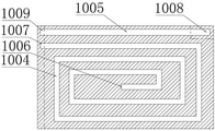
Fig. 5 is a schematic structural view of the internal structure of the L-shaped soaking plate of the present invention.
Fig. 6 is a cross-sectional view of the assembled electrode structure connection in the present invention.
The reference numbers in the figures are: 1. battery case, 101, lower casing, 102, shell lid, 2, high pressure interface, 3, low pressure interface, 4, liquid cooling interface, 5, battery cell, 501, flexible conductive part, 502, electrode head, 503, electrode cover, 504, step-like recess, 505, electrode tab, 6, base, 7, busbar, 701, bulge, 8, upper fixing frame. 9. The device comprises a U-shaped fireproof air bag, 10 a heat dissipation assembly, 1001 an L-shaped soaking plate, 1002 a liquid cooling plate, 1003, an electrode heat dissipation portion, 1004, a first heat pipe, 1005, a second heat pipe, 1006, a first evaporation end, 1007, a first condensation end, 1008, a second evaporation end, 1009, a second condensation end, 11, an I-shaped fixing plug, 12 and a T-shaped groove.
Detailed Description
The following detailed description of the embodiments of the present invention will be given in order to provide those skilled in the art with a more complete, accurate and thorough understanding of the inventive concept and technical solutions of the present invention.
As shown in fig. 1-6, the present invention provides a battery module rapid assembly and rapid heat dissipation structure, including a battery housing 1, a bus bar 7, a heat dissipation assembly 10, and a plurality of single batteries 5, wherein an electrode structure of each single battery 5 includes an electrode head 502, a flexible conductive portion 501, and an electrode sheath 503, and the flexible conductive portion 501 is a multi-layer aluminum foil with a laminated structure.
The electrode sleeve 503 is sleeved outside the electrode head 502, one end of the electrode head 502 is exposed out of the electrode sleeve 503 and is connected with an electrode jack of the busbar 7 in an inserting manner, the other end of the electrode head is welded and fixed with an electrode tab 505 of the single battery 5 through a flexible conducting part 501, a protruding part 701 is arranged at the bottom of one side provided with the electrode jack of the busbar 7, a step-shaped groove 504 matched with the protruding part 701 in shape is arranged at the lower part of the electrode sleeve 503, T-shaped grooves 12 opposite to each other are arranged on the top surface of the protruding part 701 and the top surface of the step-shaped groove 504, an I-shaped slot is formed when the electrode structure is inserted and connected to the busbar 7 in an inserting manner, the electrode sleeve 503 and the protruding part 701 are clamped and fixed through an I-shaped fixing plug 11 inserted into the I-shaped slot from the side, and the heat dissipation assembly 10 comprises a heat dissipation part inserted into a gap between the adjacent single batteries 5 from the side, an electrode heat dissipation part 1003 which contacts the electrode sleeve 503 and the protruding part 701 from the side surface is arranged on the upper side of the heat dissipation part, and the electrode heat dissipation part 1003 blocks the I-shaped fixing plug 11 after the electrode structure is connected.
The electrode sleeve 503 is made of a heat-conducting insulating material, the outer layer of the i-shaped fixing plug is wrapped by insulating elastic rubber, the insulating elastic rubber can fully expand the i-shaped slot when being heated to expand so as to position the electrode structure, and the electrode head 502 is tightly contacted with the conductive part of the electrode jack when the i-shaped slot is fully expanded by the insulating elastic rubber.
At least two heat pipes, namely a first heat pipe 1004 and a second heat pipe 1005, are arranged in the L-shaped soaking plate 1001. The condensation end 1007 of the first heat pipe 1004 is arranged at the embedded part, the first heat pipe 1004 extends from the embedded part to the plate part of the radiating part, which is in contact with the side surface of the single battery 5, the first heat pipe 1004 extends in a spiral shape, and the evaporation end 1006 of the first heat pipe is positioned at the center of the radiating part. The second condensation end 1009 of the second heat pipe 1005 is also in the embedded part, the second heat pipe 1005 extends to the heat dissipation part, the second evaporation end 1008 is located at the position of the electrode heat dissipation part 1003, and the electrode heat dissipation part 1003 protrudes towards the side, so that the evaporation end of the second heat pipe 1005 also protrudes towards two sides to form an evaporation end with a T-shaped structure.
The battery shell is characterized in that a base 6 is arranged in the battery shell 1, the base 6 is of a grid framework structure, a plurality of grid grooves for inserting the bottoms of the single batteries 5 are formed in the base 6, and heat dissipation fillers are filled in the grid grooves. The heat dissipation filler is a phase-change material, and the phase-change material is a mixture of foamed aluminum, expanded graphite and paraffin.
The length of the heat dissipation part is equal to the length of the single battery 5, the height of the heat dissipation part is 2/3 of the height of the single battery 5, the top of the heat dissipation part is located at the top of the single battery 5, support plates are fixed on two sides of the grid frame structure perpendicular to the heat dissipation part, and the height of each support plate is 1/3 of the height of the single battery 5 so as to support the heat dissipation part.
Still be equipped with U type fire prevention air pocket 9 in the battery case 1, the opening orientation of U type fire prevention air pocket 9 battery case 1 is equipped with high pressure interface 2 and one side of low pressure interface 3 simultaneously, battery cell 5 the busbar 7 form battery pack after the base 6 with heat-radiating component 10 connects, battery pack is partly cladding in U type fire prevention air pocket 9, be filled with fire extinguishing gas in the U type fire prevention air pocket 9, U type fire prevention air pocket 9 is located play cushioning effect between battery pack and the battery case 1. The U-shaped fireproof air bag 9 is made of high-temperature-resistant polyamide, and the fire extinguishing gas is heptafluoropropane.
The battery shell 1 comprises a lower shell 101, an upper fixing frame 8 and a shell cover 102, wherein a base 6, a bus bar 7, a single battery 5, a heat dissipation assembly 10 and a U-shaped fireproof air bag 9 are assembled and then placed in the lower shell 101, and the upper fixing frame 8 made of elastic rubber is assembled to the top of the battery. The lower shell 101 is provided with a high-voltage interface 2, a low-voltage interface 3 and two liquid cooling interfaces 4 on one side of the interface, the high-voltage interface 2 and the low-voltage interface 3 are connected with the busbar 7 for electrification, the two liquid cooling interfaces 4 are divided into an upper liquid inlet interface and a lower liquid outlet interface, a liquid inlet end and a liquid outlet end of a liquid cooling channel in the liquid cooling plate 1002 are correspondingly connected to the two interfaces, and the flow direction of cooling liquid in the liquid cooling channel is as shown in fig. 3.
When the invention is assembled, each single battery 5 is assembled in sequence, wherein each time the single battery 5 is assembled to connect the electrode, the electrode head 502 is firstly inserted into the electrode jack of the busbar 7 and is abutted, the connection is easier to operate and realize due to the action of the flexible conductive part 501, and in the abutted state, the corresponding T-shaped groove 12 forms an I-shaped slot, and at the moment, the connection and positioning of the electrode can be realized only by inserting the I-shaped fixing plug 11 from the opening on the side surface. When each single battery 5 is connected with the corresponding electrode jack on the bus bar 7, the operation is finished. Meanwhile, the L-shaped soaking plate 1001 and the condensing plate in the heat dissipating module 10 may be embedded and assembled, and the base 6 is put into the lower case 101, and the phase change material is filled in the base 6.
After the assembly is completed, the connected batteries and the bus bar 7 are sequentially placed in the base 6, so that the bottoms of the batteries and the bus bar are immersed in the phase-change material, the heat dissipation assembly 10 is inserted from the top, the adjacent single batteries 5 are attached to two sides of the same heat dissipation part, the adjacent electrode structures are attached to two sides of the electrode heat dissipation part 1003, and therefore the I-shaped fixing plug 11 is blocked to prevent the I-shaped fixing plug from falling off, the heat dissipation effect on the electrode part is generated, and the electrode is prevented from being burnt out due to overhigh temperature or rubber on the surface of the I-shaped fixing plug 11 is melted.
Afterwards, the liquid inlet end and the liquid outlet end of the liquid cooling channel in the condensation plate are respectively connected to the corresponding liquid cooling interface 4 on the lower shell 101, the busbar 7 and the high-voltage interface 2 and the low-voltage interface 3 on the lower shell 101 are connected, the U-shaped fireproof air bag 9 is placed between the inner wall of the lower shell 101 and the battery structure with the heat dissipation assembly 10 assembled, the upper fixing frame 8 is covered on the battery structure, the top of the busbar 7 and the top of the single battery 5 are correspondingly inserted into the fixing grooves corresponding to the upper fixing frame 8, and finally the shell cover 102 is covered to complete the assembling process of the battery module.
When needs dismantle the maintenance, only need take off cap 102 and upper mounting bracket 8 in proper order and just exposed the battery structure in the battery module, take radiator unit 10 from the top out, just reserve enough clearance and extract I shape fixing plug 11 to can directly extract the electrode joint, the aforesaid process is compared and is rotated the bolt and dismantle consuming time weak point, compare welded connection's electrode and guaranteed more to have need not the cutting and just can pull down specific battery cell 5 under the condition that does not harm electrode structural integrity, also can avoid influencing other battery cell 5.
The invention is described above with reference to the accompanying drawings, it is obvious that the specific implementation of the invention is not limited by the above-mentioned manner, and it is within the scope of the invention to adopt various insubstantial modifications of the inventive concept and solution of the invention, or to apply the inventive concept and solution directly to other applications without modification.
Claims (10)
1. The utility model provides a battery module fast assembly and quick heat radiation structure, includes battery housing (1), busbar (7), radiator unit (10) and a plurality of battery cell (5), its characterized in that: the electrode structure of the single battery (5) comprises an electrode head part (502), a flexible conductive part (501) and an electrode sleeve (503), the electrode sleeve (503) is sleeved outside the electrode head part (502), one end of the electrode head part (502) is exposed out of the electrode sleeve (503) and is connected with an electrode jack of the busbar (7) in an inserting mode, the other end of the electrode head part is welded and fixed with an electrode connecting piece (505) of the single battery (5) through the flexible conductive part (501), a protruding part (701) is arranged at the bottom of one side, provided with the electrode jack, of the busbar (7), a stepped groove (504) matched with the protruding part (701) in shape is arranged at the lower part of the electrode sleeve (503), T-shaped grooves (12) opposite to each other are formed in the top surface of the protruding part (701) and the top surface of the stepped groove (504), and an I-shaped slot is formed when the electrode structure is connected to the busbar (7) in an inserting mode, the electrode sleeve (503) and the protruding portion (701) are inserted into an I-shaped fixing plug (11) of the I-shaped slot through the side face and are clamped and fixed, the heat dissipation assembly (10) comprises a heat dissipation portion which is inserted into a gap between adjacent single batteries (5) from the side face, an electrode heat dissipation portion (1003) which is in contact with the electrode sleeve (503) and the protruding portion (701) from the side face is arranged on the upper side of the heat dissipation portion, and the electrode heat dissipation portion (1003) blocks the I-shaped fixing plug (11) after the electrode structures are connected.
2. The structure of claim 1, wherein the heat sink assembly comprises: the electrode sleeve (503) is made of a heat-conducting insulating material, the outer layer of the I-shaped fixing plug (11) is wrapped with insulating elastic rubber, the insulating elastic rubber can fully expand when heated, the I-shaped slots realize the positioning of the electrode structure, and the electrode head (502) is in close contact with the conductive parts of the electrode jacks when the I-shaped slots are fully expanded by the insulating elastic rubber.
3. The structure of claim 1 or 2, wherein the heat sink comprises: radiating component (10) are the liquid cooling subassembly, including liquid cooling board (1002) and L type soaking board (1001), liquid cooling board (1002) extending direction with the same and perpendicular to of the direction of arranging of battery cell (5) the direction that sets up of battery cell (5), L type soaking board (1001) is installed including the embedding portion and the perpendicular to of liquid cooling board (1002) one side inwards liquid cooling board (1002) the heat dissipation portion, the inside liquid cooling passageway that communicates the liquid cooling system that is equipped with of liquid cooling board (1002), electrode heat dissipation portion (1003) do the heat dissipation portion is in the convex rectangle lug of electrode structure position to the side.
4. The structure of claim 3, wherein the heat sink assembly comprises: at least two heat pipes are arranged in the L-shaped soaking plate (1001), condensing ends of the two heat pipes are arranged on the embedded part and exchange heat with the liquid cooling plate (1002), an evaporating end of one heat pipe is arranged on the electrode heat dissipation part (1003), and an evaporating end of the other heat pipe is arranged on the heat dissipation part and is positioned in the center of the single battery (5).
5. The structure of claim 4, wherein the heat sink assembly comprises: the battery is characterized in that a base (6) is arranged in the battery shell (1), the base (6) is of a grid frame structure, a plurality of grid grooves for inserting the bottoms of the single batteries (5) are formed in the base (6), and heat dissipation fillers are filled in the grid grooves.
6. The structure of claim 5, wherein the heat sink assembly comprises: the length of the heat dissipation part is equal to that of the single battery (5), the height of the heat dissipation part is 2/3 of the height of the single battery (5), the top of the heat dissipation part is located at the top of the single battery (5), support plates are fixed on two sides of the grid frame structure perpendicular to the heat dissipation part, and the height of each support plate is 1/3 of the height of the single battery (5) so as to support the heat dissipation part.
7. The structure of claim 5, wherein the heat sink assembly comprises: the heat dissipation filler is a phase-change material, and the phase-change material is a mixture of foamed aluminum, expanded graphite and paraffin.
8. The structure of claim 6, wherein the heat sink assembly comprises: still be equipped with U type fire prevention air pocket (9) in battery case (1), the opening orientation of U type fire prevention air pocket (9) battery case (1) is equipped with one side of high pressure interface (2) and low pressure interface (3), battery cell (5) busbar (7) base (6) with heat dissipation component (10) are connected the back and are formed battery pack, battery pack is partly the cladding in U type fire prevention air pocket (9), be filled with fire extinguishing gas in U type fire prevention air pocket (9), U type fire prevention air pocket (9) are located play the cushioning effect between battery pack and battery case (1).
9. The structure of claim 8, wherein the heat sink assembly comprises: the U-shaped fireproof air bag (9) is made of high-temperature-resistant polyamide, and the fire extinguishing gas is heptafluoropropane.
10. The structure of claim 1, wherein the heat sink assembly comprises: the flexible conductive part (501) is a multilayer aluminum foil with a laminated structure.
Priority Applications (1)
| Application Number | Priority Date | Filing Date | Title |
|---|---|---|---|
| CN202011291740.7A CN112421164B (en) | 2020-11-18 | 2020-11-18 | Battery module fast assembly and quick heat radiation structure |
Applications Claiming Priority (1)
| Application Number | Priority Date | Filing Date | Title |
|---|---|---|---|
| CN202011291740.7A CN112421164B (en) | 2020-11-18 | 2020-11-18 | Battery module fast assembly and quick heat radiation structure |
Publications (2)
| Publication Number | Publication Date |
|---|---|
| CN112421164A CN112421164A (en) | 2021-02-26 |
| CN112421164B true CN112421164B (en) | 2022-04-15 |
Family
ID=74831680
Family Applications (1)
| Application Number | Title | Priority Date | Filing Date |
|---|---|---|---|
| CN202011291740.7A Active CN112421164B (en) | 2020-11-18 | 2020-11-18 | Battery module fast assembly and quick heat radiation structure |
Country Status (1)
| Country | Link |
|---|---|
| CN (1) | CN112421164B (en) |
Families Citing this family (2)
| Publication number | Priority date | Publication date | Assignee | Title |
|---|---|---|---|---|
| CN113991215B (en) * | 2021-10-28 | 2024-06-25 | 深圳市顺熵科技有限公司 | Power battery module, power battery pack and thermal management method thereof |
| CN114050378B (en) * | 2021-11-02 | 2023-06-02 | 国网湖北省电力有限公司宜昌供电公司 | Cartridge clip type direct current storage battery module |
Family Cites Families (13)
| Publication number | Priority date | Publication date | Assignee | Title |
|---|---|---|---|---|
| EP2660899B1 (en) * | 2010-12-28 | 2018-08-29 | LG Chem, Ltd. | Battery module storage device, and electric power storage system having same |
| US9761850B2 (en) * | 2011-10-28 | 2017-09-12 | Nucleus Scientific, Inc. | Multi-cell battery assembly |
| KR101987773B1 (en) * | 2012-07-16 | 2019-06-11 | 에스케이이노베이션 주식회사 | Battery pack |
| CN104752639B (en) * | 2013-12-31 | 2017-07-04 | 比亚迪股份有限公司 | Electrokinetic cell module |
| DE102014212264A1 (en) * | 2014-06-26 | 2015-12-31 | Robert Bosch Gmbh | Cell connector and battery cell, battery module, battery, battery system, vehicle and method for manufacturing a battery module |
| CN104810491B (en) * | 2015-03-27 | 2017-06-06 | 北京航空航天大学 | A kind of battery protection and temperature-controlling system |
| KR20170002082A (en) * | 2015-06-29 | 2017-01-06 | 삼성에스디아이 주식회사 | Battery pack |
| KR20170014555A (en) * | 2015-07-30 | 2017-02-08 | 삼성에스디아이 주식회사 | Battery pack |
| CN105826499A (en) * | 2016-04-29 | 2016-08-03 | 郑州宇通客车股份有限公司 | Lithium battery pack utilizing phase-change material to realize temperature control |
| KR102119152B1 (en) * | 2017-12-12 | 2020-06-04 | 삼성에스디아이 주식회사 | Battery Pack |
| CN109301125A (en) * | 2018-11-23 | 2019-02-01 | 北斗航天汽车(北京)有限公司 | Electri forklift battery module structure and battery pack |
| CN211320174U (en) * | 2019-09-09 | 2020-08-21 | 福建易动力电子科技股份有限公司 | Fire extinguishing device of explosion-proof power box |
| CN111952508A (en) * | 2020-09-08 | 2020-11-17 | 柳州市智甲金属科技有限公司 | Battery pack assembly based on integrated battery pack box body |
-
2020
- 2020-11-18 CN CN202011291740.7A patent/CN112421164B/en active Active
Also Published As
| Publication number | Publication date |
|---|---|
| CN112421164A (en) | 2021-02-26 |
Similar Documents
| Publication | Publication Date | Title |
|---|---|---|
| CN112421164B (en) | Battery module fast assembly and quick heat radiation structure | |
| KR102403695B1 (en) | Rechargeable battery and module thereof | |
| CN111584978A (en) | Battery module | |
| CN103517467B (en) | A kind of PTC electric heating element, electric heater unit and electric motor car | |
| WO2023072224A1 (en) | Cylindrical cell module | |
| WO2022151822A1 (en) | Battery assembly and electric vehicle | |
| CN113555632B (en) | Battery pack | |
| CN216145746U (en) | Battery pack circuit breaking unit device and battery pack | |
| CN116528535B (en) | Electric connector assembly structure, distribution box and preparation method of distribution box | |
| CN108583217A (en) | A kind of automobile air-conditioner high-pressure heating water PTC assemblies with equipotential design | |
| CN218182418U (en) | Battery with a battery cell | |
| CN218351556U (en) | Battery core tab cooling structure and battery pack | |
| CN208134020U (en) | A kind of automobile air-conditioner high-pressure heating water PTC assembly with equipotential design | |
| CN114464918B (en) | Battery pack | |
| CN201986315U (en) | Motor controller and transportation equipment comprising the same | |
| CN114552053B (en) | High-integration battery pack | |
| CN115441086A (en) | Welding and grouping method for liquid cooling heat dissipation structures of energy storage battery pack | |
| CN114927796A (en) | Lithium ion battery with battery overheating prevention structure and preparation process | |
| CN114725563A (en) | Battery module, battery pack heat management device and system | |
| CN211182299U (en) | Battery pack lower box body and battery pack | |
| CN111435724B (en) | Battery module, battery system with same and electric vehicle | |
| CN111435716B (en) | Battery system, mounting case thereof and electric vehicle having the same | |
| CN112993474A (en) | Battery pack lower box body and battery pack | |
| CN220155601U (en) | Battery module, energy storage system, power station and charging network | |
| CN215896621U (en) | Battery module and battery pack |
Legal Events
| Date | Code | Title | Description |
|---|---|---|---|
| PB01 | Publication | ||
| PB01 | Publication | ||
| SE01 | Entry into force of request for substantive examination | ||
| SE01 | Entry into force of request for substantive examination | ||
| GR01 | Patent grant | ||
| GR01 | Patent grant |