CN112408243A - Automatic goods shelf of stereoscopic warehouse - Google Patents
Automatic goods shelf of stereoscopic warehouse Download PDFInfo
- Publication number
- CN112408243A CN112408243A CN202011534107.6A CN202011534107A CN112408243A CN 112408243 A CN112408243 A CN 112408243A CN 202011534107 A CN202011534107 A CN 202011534107A CN 112408243 A CN112408243 A CN 112408243A
- Authority
- CN
- China
- Prior art keywords
- rope
- fixedly connected
- automatic
- motor
- stereoscopic warehouse
- Prior art date
- Legal status (The legal status is an assumption and is not a legal conclusion. Google has not performed a legal analysis and makes no representation as to the accuracy of the status listed.)
- Pending
Links
Images


Classifications
-
- B—PERFORMING OPERATIONS; TRANSPORTING
- B66—HOISTING; LIFTING; HAULING
- B66F—HOISTING, LIFTING, HAULING OR PUSHING, NOT OTHERWISE PROVIDED FOR, e.g. DEVICES WHICH APPLY A LIFTING OR PUSHING FORCE DIRECTLY TO THE SURFACE OF A LOAD
- B66F7/00—Lifting frames, e.g. for lifting vehicles; Platform lifts
- B66F7/02—Lifting frames, e.g. for lifting vehicles; Platform lifts with platforms suspended from ropes, cables, or chains or screws and movable along pillars
-
- B—PERFORMING OPERATIONS; TRANSPORTING
- B65—CONVEYING; PACKING; STORING; HANDLING THIN OR FILAMENTARY MATERIAL
- B65G—TRANSPORT OR STORAGE DEVICES, e.g. CONVEYORS FOR LOADING OR TIPPING, SHOP CONVEYOR SYSTEMS OR PNEUMATIC TUBE CONVEYORS
- B65G1/00—Storing articles, individually or in orderly arrangement, in warehouses or magazines
- B65G1/02—Storage devices
- B65G1/04—Storage devices mechanical
-
- B—PERFORMING OPERATIONS; TRANSPORTING
- B66—HOISTING; LIFTING; HAULING
- B66F—HOISTING, LIFTING, HAULING OR PUSHING, NOT OTHERWISE PROVIDED FOR, e.g. DEVICES WHICH APPLY A LIFTING OR PUSHING FORCE DIRECTLY TO THE SURFACE OF A LOAD
- B66F7/00—Lifting frames, e.g. for lifting vehicles; Platform lifts
- B66F7/28—Constructional details, e.g. end stops, pivoting supporting members, sliding runners adjustable to load dimensions
Landscapes
- Engineering & Computer Science (AREA)
- Mechanical Engineering (AREA)
- Life Sciences & Earth Sciences (AREA)
- Geology (AREA)
- Structural Engineering (AREA)
- Warehouses Or Storage Devices (AREA)
Abstract
The invention relates to the technical field of warehouse storage, in particular to an automatic goods shelf for a stereoscopic warehouse, which comprises a top mounting plate, a connecting rope and a placing plate, wherein rope hoisting and receiving devices which are symmetrically arranged in the front and back are fixedly mounted on the bottom end surface of the top mounting plate, the connecting rope is wound on the inner side of each rope hoisting and receiving device, mounting holes are uniformly formed in the outer side of the placing plate, the inner sides of the mounting holes are in sliding connection with the connecting rope, automatic rope fastening devices are arranged on the lower sides of the mounting holes and are attached to the connecting rope, and automatic goods limiting devices are uniformly mounted on the placing plate.
Description
Technical Field
The invention relates to the technical field of warehouse storage, in particular to an automatic goods shelf of a stereoscopic warehouse.
Background
The stereoscopic warehouse is a warehouse which adopts a high-rise goods shelf to store goods by using containers or trays and uses a roadway stacking crane and other machinery to operate, in the stereoscopic warehouse, the height of the goods shelf is generally greater than that of a single-layer warehouse, the stereoscopic warehouse is an important logistics node in a modern logistics system, and the stereoscopic warehouse is more and more commonly applied in logistics centers. The current highest stereoscopic warehouse in the world has the height of 50 meters, and the storage capacity of the stereoscopic warehouse per unit area can reach 7.5 (t/m)2) 5-10 times of common warehouse, and the storage area can greatly store goods due to the high-rise goods shelfThe ground is developed to the high altitude, and the warehouse ground and the space are fully utilized, so that the storage floor area is saved, and the space utilization rate is improved. The operation and processing speed is high by using mechanical and automatic equipment, the labor productivity is improved, and the labor intensity of operators is reduced. The automatic stereoscopic warehouse is the highest stage of the development of the modern goods shelf storage system, and is called three major signs of logistics technology modernization together with an automatic sorting system and an automatic guide vehicle.
Most stereoscopic warehouse automatic goods shelves that exist on the existing market are mostly that the support body is fixed to be set up, and this kind of setting makes the goods shelves wholly be not convenient for adjust, and then makes the goods shelves when placing the goods, can not be better adjust goods shelves to the volume of goods to certain usage space has been wasted, has reduced the volume of depositing of goods shelves to the goods, consequently, provides a stereoscopic warehouse automatic goods shelves to above-mentioned problem.
Disclosure of Invention
The invention aims to provide an automatic goods shelf of a stereoscopic warehouse, which solves the problems in the background technology.
In order to achieve the purpose, the invention provides the following technical scheme:
the utility model provides an automatic goods shelves of stereoscopic warehouse, includes the top mounting panel, connects the rope and places the board, the bottom face fixed mounting of top mounting panel has the rope that is the front and back symmetry and sets up to lift by crane storage device, the inboard roll-up of rope lift by crane storage device has the connection rope, place the even mounting hole of having seted up in the outside of board, the inboard and the connection rope sliding connection of mounting hole, the downside of mounting hole is equipped with automatic fastener of rope, and automatic fastener of rope and the laminating of being connected the rope.
Preferably, the placing plate is uniformly provided with an automatic goods limiting device.
Preferably, the left side and the right side of the placing plate are both arranged in an inward concave manner, and the automatic cargo limiting devices are uniformly arranged on the top end face of the placing plate.
Preferably, the rope lifting and accommodating device comprises a lifting motor and a take-up pulley, the lifting motor is arranged around the bottom end face of the top mounting plate and is arranged in a double-output shaft mode, the take-up pulley is fixedly connected to the outer side of a main shaft of the lifting motor, a connecting rope is arranged on the outer side of the take-up pulley, supports are arranged on two sides of the take-up pulley, the top ends of the supports are fixedly connected with the top mounting plate, and a lifting motor protection mechanism is arranged on the main shaft of the lifting motor.
Preferably, lift by crane motor protection mechanism and include ratchet, pawl, support, metal block and electro-magnet, fixedly connected with ratchet on the main shaft of lifting by crane the motor, the outside of ratchet is equipped with the pawl, the other end of pawl articulates there is the support, support and top mounting panel fixed connection, the outside fixedly connected with metal block of pawl, and be equipped with the electro-magnet directly over the metal block, the top and the top mounting panel fixed connection of electro-magnet.
Preferably, the automatic rope fastening device comprises a clamping plate, a fixing shaft, an outer ring, a fastening motor, a gear and a toothed ring, the fixing shaft is fixedly connected with the bottom end face of the placing plate, the clamping plate is rotatably connected to the outer side of the fixing shaft, the outer ring is spirally connected to the outer side of the clamping plate, the fastening motor is fixedly connected to the bottom end face of the placing plate, the gear is fixedly connected to the tail end of a main shaft of the fastening motor, the toothed ring is meshed to the outer side of the gear, and the toothed ring is sleeved on the outer side of the outer ring.
Preferably, the inner side of the clamping plate is uniformly and fixedly connected with anti-skidding blocks, and the cross sections of the anti-skidding blocks are arranged in an inverted triangle.
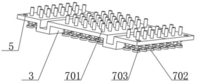
Preferably, the automatic goods limiting device comprises a limiting rod, a through hole is uniformly formed in the top end face of the placing plate, the limiting rod is connected in the through hole in a sliding mode, a limiting plate is fixedly connected to the bottom end of the limiting rod, a reset spring is fixedly connected to the outer side of the top end face of the limiting plate, and the top end of the reset spring is fixedly connected with the placing plate.
Compared with the prior art, the invention has the beneficial effects that:
according to the invention, the goods shelf can be changed from a fixed connection support structure to a movable connection support structure through the arranged rope hoisting and containing device, the connection rope and the automatic rope fastening device, so that the whole device is convenient to contract, retract, release and adjust.
Drawings
FIG. 1 is a schematic view of the overall structure of the present invention;
FIG. 2 is a schematic structural view of a rope hoisting storage device according to the present invention;
FIG. 3 is a schematic view of an electromagnet mounting structure according to the present invention;
fig. 4 is a schematic view of the automatic rope fastening device of the present invention;
fig. 5 is a schematic structural view of the automatic cargo limiting device of the present invention.
In the figure: the device comprises a 1-top mounting plate, a 2-connecting rope, a 3-placing plate, a 4-rope hoisting and receiving device, a 401-hoisting motor, a 402-take-up pulley, a 403-bracket, a 404-ratchet wheel, a 405-pawl, a 406-support, a 407-metal block, a 408-electromagnet, a 5-mounting hole, a 6-rope automatic fastening device, a 601-clamping plate, a 602-fixing shaft, a 603-outer ring, a 604-fastening motor, a 605-gear, a 606-toothed ring, a 607-anti-slip block, a 7-cargo automatic limiting device, a 701-limiting rod, a 702-limiting plate and a 703-reset spring.
Detailed Description
Example 1: referring to fig. 1-5, the present invention provides a technical solution:
the utility model provides an automatic goods shelves of stereoscopic warehouse, including top mounting panel 1, connect rope 2 and place board 3, top mounting panel 1's bottom face fixed mounting has the rope lifting storage device 4 that is the front and back symmetry setting, the inboard roll-up of rope lifting storage device 4 has connection rope 2, place the even mounting hole 5 of having seted up in the outside of board 3, the inboard and the connection rope 2 sliding connection of mounting hole 5, the downside of mounting hole 5 is equipped with automatic fastener of rope 6, and automatic fastener of rope 6 with connect 2 laminatings of rope, place the even automatic stop device 7 of goods of installing on board 3, this kind of setting can make goods shelves change movable connection bearing structure into by fixed connection bearing structure, thereby the device is whole not only to be convenient for the shrink receive and release, and be convenient for adjust the use.
The left side and the right side of the placing plate 3 are both arranged in an inward concave manner, and the automatic cargo limiting device 7 is uniformly arranged on the top end surface of the placing plate 3, the arrangement is convenient for a forklift to take and place cargos and can better limit cargos, the rope lifting and receiving device 4 comprises a lifting motor 401 and a take-up pulley 402, the bottom end surface of the top mounting plate 1 is fixedly connected with the lifting motor 401 which is arranged in the front and back direction, the lifting motor 401 is arranged in a double-output shaft manner, the take-up pulley 402 is fixedly connected to the outer side of a main shaft of the lifting motor 401, a connecting rope 2 is arranged on the outer side of the take-up pulley 402, two sides of the take-up pulley 402 are respectively provided with a bracket 403, the top end of the bracket 403 is fixedly connected with the top mounting plate 1, a lifting motor protection mechanism is arranged on the main shaft of the lifting motor 401, the arrangement can, the hoisting motor protection mechanism comprises a ratchet wheel 404, a pawl 405, a support 406, a metal block 407 and an electromagnet 408, the ratchet wheel 404 is fixedly connected to a main shaft of the hoisting motor 401, the pawl 405 is arranged on the outer side of the ratchet wheel 404, the support 406 is hinged to the other end of the pawl 405, the support 406 is fixedly connected with the top mounting plate 1, the metal block 407 is fixedly connected to the outer side of the pawl 405, the electromagnet 408 is arranged right above the metal block 407, the top end of the electromagnet 408 is fixedly connected with the top mounting plate 1, the load of the motor can be effectively relieved by the arrangement, the service life of the motor is guaranteed, the automatic rope fastening device 6 comprises a clamping plate 601, a fixed shaft 602, an outer ring 603, a fastening motor 604, a gear 605 and a toothed ring 606, the bottom end face of the placing plate 3 is uniformly and fixedly connected with the fixed shaft 602, the clamping plate 601 is rotatably connected to, the bottom end face of the placing plate 3 is fixedly connected with a fastening motor 604, the tail end of a main shaft of the fastening motor 604 is fixedly connected with a gear 605, the outer side of the gear 605 is meshed with a toothed ring 606, the toothed ring 606 is sleeved on the outer side of the outer ring 603, the arrangement can better fix the connecting rope 2, so that the stability of the connection of the placing plate 3 and the connecting rope 2 is ensured, the inner side of the clamping plate 601 is uniformly and fixedly connected with anti-skidding blocks 607, the cross sections of the anti-skidding blocks 607 are arranged in an inverted triangle, the arrangement can play a better anti-skidding effect and ensure the stability of the fixation of the placing plate 3, the automatic goods limiting device 7 comprises a limiting rod 701, the top end face of the placing plate 3 is uniformly provided with through holes, the limiting rod 701 is connected in the through holes in a sliding manner, the bottom end of the limiting rod 701 is fixedly connected with a limiting plate 702, and reset spring 703's top with place board 3 fixed connection, this kind of position can be better restrict the outside of goods and handle to the effectual goods of having guaranteed can not slide, guaranteed the stability that the goods was placed.
The working process is as follows: when the device is used, an external power supply is switched on, then goods are firstly placed on the placing plate 3 on the top side through a forklift, then the goods press down the limiting rod 701 below the goods, the placing stability of the goods is ensured, the limiting rod 701 on the outer side can well play a limiting effect on the goods and prevent the goods from sliding, then the fastening motor 604 on the bottom side of the placing plate 3 on the top side rotates, further the gear 605 and the toothed ring 606 drive the rotation of the outer side, further the fastening effect on the clamping plate 601 is realized, the fixing effect on the connecting rope 2 is realized by matching with the anti-skid block 607, then the hoisting motor 401 on the top is started, further the connecting rope is recycled through the take-up pulley 402, further the goods are hoisted, then the goods are continuously placed on the second placing plate 3, then the goods are hoisted in sequence, the ratchet 404 and the pawl 405 are arranged, the main shaft of the hoisting motor 401 can be effectively played to a limiting effect, therefore, the load of the lifting motor 401 is effectively relieved, the service life of the lifting motor 401 is guaranteed, finally, when the goods need to be put down, the electromagnet 408 is started, then the lifting motor 401 rotates forwards first, the clamping and the state of the ratchet 404 and the pawl 405 are relieved, then the pawl 405 is lifted through the electromagnet 408 and the metal block 407, and then the lifting motor 401 rotates backwards, and the goods are put down.
The principles and embodiments of the present invention are explained herein using specific examples, which are presented only to assist in understanding the method and its core concepts of the present invention. The foregoing is only a preferred embodiment of the present invention, and it should be noted that there are objectively infinite specific structures due to the limited character expressions, and it will be apparent to those skilled in the art that a plurality of modifications, decorations or changes may be made without departing from the principle of the present invention, and the technical features described above may be combined in a suitable manner; such modifications, variations, combinations, or adaptations of the invention using its spirit and scope, as defined by the claims, may be directed to other uses and embodiments.
Claims (8)
1. The utility model provides an automatic goods shelves of stereoscopic warehouse, includes top mounting panel (1), connects rope (2) and places board (3), its characterized in that: the utility model discloses a rope lifting and storage device, including top mounting panel (1), rope lifting and storage device (4) that the bottom face fixed mounting of top mounting panel (1) was equipped with around being symmetry and sets up, the inboard roll-up of rope lifting and storage device (4) has connection rope (2), place the even mounting hole (5) of having seted up in the outside of board (3), the inboard and the connection rope (2) sliding connection of mounting hole (5), the downside of mounting hole (5) is equipped with automatic fastener of rope (6), and automatic fastener of rope (6) with be connected rope (2) and laminate.
2. The stereoscopic warehouse automatic shelf according to claim 1, wherein: the placing plate (3) is uniformly provided with an automatic goods limiting device (7).
3. The stereoscopic warehouse automatic shelf according to claim 2, wherein: the left side and the right side of the placing plate (3) are both arranged in an inward concave manner, and the automatic cargo limiting devices (7) are uniformly arranged on the top end face of the placing plate (3).
4. The stereoscopic warehouse automatic shelf according to claim 1, wherein: rope lifts by crane storage device (4) including lifting by crane motor (401) and take-up pulley (402), top mounting panel (1) bottom face fixedly connected with lifts by crane motor (401) that sets up around being, and lifts by crane motor (401) and set up for two play axles, the main shaft outside fixedly connected with take-up pulley (402) of lifting by crane motor (401), the outside of take-up pulley (402) is equipped with connecting rope (2), the both sides of take-up pulley (402) all are equipped with support (403), and the top and top mounting panel (1) fixed connection of support (403), it lifts by crane motor protection mechanism to install on the main shaft of motor (401).
5. The stereoscopic warehouse automatic shelf according to claim 4, wherein: the protection mechanism of the hoisting motor comprises a ratchet wheel (404), a pawl (405), a support (406), a metal block (407) and an electromagnet (408), wherein the ratchet wheel (404) is fixedly connected to a main shaft of the hoisting motor (401), the pawl (405) is arranged on the outer side of the ratchet wheel (404), the support (406) is hinged to the other end of the pawl (405), the support (406) is fixedly connected with a top mounting plate (1), the metal block (407) is fixedly connected to the outer side of the pawl (405), the electromagnet (408) is arranged right above the metal block (407), and the top end of the electromagnet (408) is fixedly connected with the top mounting plate (1).
6. The stereoscopic warehouse automatic shelf according to claim 1, wherein: the automatic rope fastening device (6) comprises a clamping plate (601), a fixed shaft (602), an outer ring (603), a fastening motor (604), a gear (605) and a toothed ring (606), wherein the fixed shaft (602) is fixedly connected to the bottom end face of the placing plate (3) uniformly, the clamping plate (601) is rotatably connected to the outer side of the fixed shaft (602), the outer ring (603) is spirally connected to the outer side of the clamping plate (601), the fastening motor (604) is fixedly connected to the bottom end face of the placing plate (3), the gear (605) is fixedly connected to the tail end of a main shaft of the fastening motor (604), the toothed ring (606) is meshed to the outer side of the gear (605), and the toothed ring (606) is sleeved on the outer side of the outer ring (603).
7. The stereoscopic warehouse automatic shelf according to claim 6, wherein: the inner side of the clamping plate (601) is uniformly and fixedly connected with anti-skidding blocks (607), and the cross sections of the anti-skidding blocks (607) are arranged in an inverted triangle.
8. The stereoscopic warehouse automatic shelf according to claim 2, wherein: the automatic goods limiting device (7) comprises a limiting rod (701), the top end face of the placing plate (3) is uniform, a through hole is formed in the top end face, the limiting rod (701) is connected in the through hole in a sliding mode, the bottom end of the limiting rod (701) is fixedly connected with a limiting plate (702), the outer side of the top end face of the limiting plate (702) is fixedly connected with a reset spring (703), and the top end of the reset spring (703) is fixedly connected with the placing plate (3).
Priority Applications (1)
| Application Number | Priority Date | Filing Date | Title |
|---|---|---|---|
| CN202011534107.6A CN112408243A (en) | 2020-12-23 | 2020-12-23 | Automatic goods shelf of stereoscopic warehouse |
Applications Claiming Priority (1)
| Application Number | Priority Date | Filing Date | Title |
|---|---|---|---|
| CN202011534107.6A CN112408243A (en) | 2020-12-23 | 2020-12-23 | Automatic goods shelf of stereoscopic warehouse |
Publications (1)
| Publication Number | Publication Date |
|---|---|
| CN112408243A true CN112408243A (en) | 2021-02-26 |
Family
ID=74782458
Family Applications (1)
| Application Number | Title | Priority Date | Filing Date |
|---|---|---|---|
| CN202011534107.6A Pending CN112408243A (en) | 2020-12-23 | 2020-12-23 | Automatic goods shelf of stereoscopic warehouse |
Country Status (1)
| Country | Link |
|---|---|
| CN (1) | CN112408243A (en) |
Cited By (1)
| Publication number | Priority date | Publication date | Assignee | Title |
|---|---|---|---|---|
| CN114657996A (en) * | 2022-02-28 | 2022-06-24 | 中国五冶集团有限公司 | Fill rubble device |
-
2020
- 2020-12-23 CN CN202011534107.6A patent/CN112408243A/en active Pending
Cited By (2)
| Publication number | Priority date | Publication date | Assignee | Title |
|---|---|---|---|---|
| CN114657996A (en) * | 2022-02-28 | 2022-06-24 | 中国五冶集团有限公司 | Fill rubble device |
| CN114657996B (en) * | 2022-02-28 | 2024-07-23 | 中国五冶集团有限公司 | Filling stone crushing device |
Similar Documents
| Publication | Publication Date | Title |
|---|---|---|
| CN106080351B (en) | A kind of handling method of Self-loading-unloading boxcar | |
| CN206926660U (en) | A kind of municipal administration trolley | |
| CN208377623U (en) | A kind of storage rack conveniently taking object | |
| CN109665339A (en) | A kind of boxcar cargo gear | |
| CN112408243A (en) | Automatic goods shelf of stereoscopic warehouse | |
| CN102794759A (en) | Carrying robot | |
| CN213895052U (en) | Automatic goods shelf of stereoscopic warehouse | |
| CN213058711U (en) | Supporting integral type loading and unloading handling device of storage rack | |
| CN213141195U (en) | Straddle carrier lifting system | |
| CN219689121U (en) | Storage commodity circulation hoist mechanism that barrier property is high | |
| CN109484826B (en) | Aviation tray lifting and overturning device | |
| CN215666679U (en) | Three-hoisting-point trolley | |
| CN208561595U (en) | A kind of scalable carrier of pallet fork length | |
| CN209536506U (en) | A kind of boxcar cargo gear | |
| CN107605210A (en) | Novel elevating machine plane movable parking equipment | |
| CN221796953U (en) | Fork truck portal location actuating system with PLC control | |
| CN106684760B (en) | The dragger that a kind of aerial work uses | |
| CN220351477U (en) | Stable crane | |
| CN221296054U (en) | Manual tray carrier with good stability | |
| CN220563429U (en) | Three-dimensional goods shelf with hoisting mechanism | |
| CN210259831U (en) | Intelligent stacking equipment | |
| CN205133058U (en) | Carrier with play to rise decline complementary unit | |
| CN214777723U (en) | Electronic commerce is with intelligent cargo handling device | |
| CN217387911U (en) | Power distribution cabinet capable of simultaneously hoisting and supporting | |
| CN219860364U (en) | Lifting equipment for multilayer cargo carrying platform |
Legal Events
| Date | Code | Title | Description |
|---|---|---|---|
| PB01 | Publication | ||
| PB01 | Publication | ||
| SE01 | Entry into force of request for substantive examination | ||
| SE01 | Entry into force of request for substantive examination |