CN112405882A - Hole-adopted adjustable chain arm saw - Google Patents
Hole-adopted adjustable chain arm saw Download PDFInfo
- Publication number
- CN112405882A CN112405882A CN202011264081.8A CN202011264081A CN112405882A CN 112405882 A CN112405882 A CN 112405882A CN 202011264081 A CN202011264081 A CN 202011264081A CN 112405882 A CN112405882 A CN 112405882A
- Authority
- CN
- China
- Prior art keywords
- gear
- driving motor
- saddle
- bottom saddle
- slide rail
- Prior art date
- Legal status (The legal status is an assumption and is not a legal conclusion. Google has not performed a legal analysis and makes no representation as to the accuracy of the status listed.)
- Pending
Links
Images


Classifications
-
- B—PERFORMING OPERATIONS; TRANSPORTING
- B28—WORKING CEMENT, CLAY, OR STONE
- B28D—WORKING STONE OR STONE-LIKE MATERIALS
- B28D1/00—Working stone or stone-like materials, e.g. brick, concrete or glass, not provided for elsewhere; Machines, devices, tools therefor
- B28D1/02—Working stone or stone-like materials, e.g. brick, concrete or glass, not provided for elsewhere; Machines, devices, tools therefor by sawing
- B28D1/08—Working stone or stone-like materials, e.g. brick, concrete or glass, not provided for elsewhere; Machines, devices, tools therefor by sawing with saw-blades of endless cutter-type, e.g. chain saws, i.e. saw chains, strap saws
- B28D1/088—Sawing in situ, e.g. stones from rocks, grooves in walls
-
- B—PERFORMING OPERATIONS; TRANSPORTING
- B28—WORKING CEMENT, CLAY, OR STONE
- B28D—WORKING STONE OR STONE-LIKE MATERIALS
- B28D7/00—Accessories specially adapted for use with machines or devices of the preceding groups
Abstract
The invention discloses an adjustable chain arm saw for a hole, which comprises a main case, wherein a rack is arranged on the front side of the main case, first stand columns are arranged on two sides of the rack, a second stand column is welded on one side of the first stand column, a first bottom saddle is arranged at the top end of the second stand column, a second bottom saddle is arranged on one side of the first bottom saddle, a headstock is arranged on one side of the second bottom saddle, first adjusting mechanisms are arranged at two ends of the first bottom saddle, a second adjusting mechanism is arranged at one end of the second bottom saddle, and a third adjusting mechanism is arranged at one end of the headstock. When downward cutting is needed, the first bevel gear drives the second bevel gear to rotate, the second bevel gear drives the first gear to rotate, the first gear, the second gear and the third gear drive the pulley to slide along the third sliding rail to reach the designated position, and when transverse cutting is needed, the second adjusting mechanism can adjust the chain arm saw body through multiple angles, so that the labor use is reduced, and the working efficiency is improved.
Description
Technical Field
The invention relates to the field of chain arm saws, in particular to an adjustable chain arm saw for holes.
Background
The stone is the oldest building and decoration material in human history and is also a carrier of art and culture, the stone industry in China is still in the rough development stage generally at present, most enterprises have the characteristics of 'small, soil, scattered and disorderly', the production process and technical equipment are backward, the core competitiveness is lacked, the scale superiority and the industrial cluster are not favorably formed, along with the improvement of society and the improvement of economic level, the demand of people on high-quality stone is more and more increased, the traditional exploitation method by blasting has the biggest problem that stress waves easily damage the interior of the stone, on one hand, the shape of the exploited stone is irregular, the processing difficulty is increased, the stone process value is reduced, on the other hand, the collapse of mountain bodies is easily caused by adopting the blasting method, the life and property safety of operators are seriously threatened, in addition, the traditional exploitation method has low efficiency, and simultaneously high-strength manual operation is needed for matching, the environment can be seriously damaged, and the automatic recovery capability of the environment is influenced.
Traditionally, the form of grooving splitting or rope saw mining is adopted, the mining efficiency is low in the mode, the mining surface is uneven, the quality of the mined stone is poor, the secondary processing amount is large, the raw material mining rate is low, a large amount of manpower and material resources are used in the mining process, and the mining cost is high.
Therefore, there is a need for a hole that employs an adjustable chain arm saw to solve the above problems.
Disclosure of Invention
The invention aims to provide an adjustable chain arm saw for a hole, when undercutting is needed, a first adjusting mechanism is started to work, a first bevel gear is enabled to be meshed in a rotating mode to drive a second bevel gear to rotate, the second bevel gear rotates to drive a first gear to rotate through a rotating shaft, the first gear rotates to drive a second gear and a plurality of third gears to rotate through a chain, then the first gear, the second gear and the plurality of third gears drive a plurality of pulleys through a rotating shaft to simultaneously rotate and slide downwards along a third sliding rail until the third sliding rail reaches a specified position, when crosscutting is needed, the second adjusting mechanism is started to work, the first gear, the second gear and the plurality of third gears drive a plurality of pulleys through the rotating shaft to simultaneously rotate and slide leftwards and rightwards along the second sliding rail until the specified position is reached, further, the third adjusting mechanism is started to work, the first gear, the second gear and the plurality of third gears drive the plurality of pulleys to simultaneously rotate through the rotating shaft and slide leftwards and rightwards along the first sliding rail Move until reaching the assigned position can, adjust the chain arm saw body through the multi-angle to not only reduced the manpower and used, improved work efficiency moreover, in order to solve the above-mentioned weak point in the technique.
In order to achieve the above purpose, the invention provides the following technical scheme: the utility model provides a hole adopts adjustable chain arm saw, includes the mainframe box, the front side of mainframe box is equipped with the frame, the bilateral symmetry welding of frame has first stand, two one side that the frame was kept away from to first stand all has welded the second stand, two top one side of second stand is equipped with first end saddle jointly, one side that two first stands were kept away from to first end saddle is provided with second end saddle, one side that first end saddle was kept away from to second end saddle is provided with the headstock, first end saddle and two both sides of second stand have welded first slide rail, second slide rail and third slide rail respectively, the both ends symmetry of first end saddle is equipped with two first adjustment mechanism, one end one side of second end saddle is equipped with two second adjustment mechanism, one end one side of headstock is equipped with two third adjustment mechanism, first adjustment mechanism, Second adjustment mechanism and third adjustment mechanism all include with first end saddle, second end saddle and headstock welded fastening's U type connecting piece, be equipped with first interior chamber and second interior chamber in the lateral wall of U type connecting piece, be provided with the first driving motor that is the level setting in the first interior chamber, first driving motor's output rotates through the pivot and is connected with first bevel gear, first bevel gear's meshing in proper order has the second bevel gear, bottom one side center department of second bevel gear runs through to extend to second interior chamber and is connected with first gear through the pivot rotation, one side of first gear is equipped with the second gear, evenly be equipped with a plurality of third gears between second gear and the first gear, second gear and a plurality of third gear mesh jointly and are connected with the chain, one side center department of first gear, second gear and a plurality of third gear all runs through to extend to in the U type connecting piece through the pivot The rotary connection has the pulley, and is a plurality of the pulley respectively with correspond first slide rail, second slide rail and third slide rail sliding connection.
Preferably, the welding of one side that the saddle was kept away from at the bottom of the second to the headstock has the assembly seat, the welding of one side of assembly seat has the work box, be provided with the second driving motor who is perpendicular setting in the work box, second driving motor's output rotates and is connected with first threaded rod, the meshing of one side of the one end that second driving motor was kept away from to first threaded rod is connected with the fourth gear, one side center department of fourth gear is connected with the roating seat through being connected with behind the pivot running through the work box.
Preferably, one side welding that the work box was kept away from to the roating seat has the regulation frame, be provided with third driving motor in the regulation frame, third driving motor's output rotates and is connected with the rotation axis, the one end welding that the rotation axis runs through behind the regulation frame has the rotation connecting piece, the welding of one side of rotating the connecting piece has the chain arm saw body.
Preferably, the bottom of mainframe box one side both ends symmetry welding have the supporting leg, two the bottom of supporting leg all is equipped with first ejecting hydro-cylinder.
Preferably, the top ends of the two second upright columns are provided with second ejection oil cylinders, and the bottom ends of the two second upright columns are provided with third ejection oil cylinders.
Preferably, an assembly support is provided at one side of the main cabinet.
Preferably, the two ends of one side of the rack are symmetrically provided with connecting seats, and each connecting seat is rotatably connected with the assembling support through a rotating shaft.
In the technical scheme, the invention provides the following technical effects and advantages:
1. when downward cutting is needed, the first adjusting mechanism is started to work, the first bevel gear is enabled to be meshed in a rotating mode to drive the second bevel gear to rotate, the second bevel gear rotates to drive the first gear to rotate through the rotating shaft, the first gear rotates to drive the second gear and the plurality of third gears to rotate through the chain, then the first gear, the second gear and the plurality of third gears drive the plurality of pulleys to simultaneously rotate and slide downwards along the third slide rail until the first gear reaches a specified position through the rotating shaft, when transverse cutting is needed, the second adjusting mechanism is started to work, the first gear, the second gear and the plurality of third gears drive the plurality of pulleys to simultaneously rotate and slide leftwards and rightwards along the second slide rail until the second slide rail reaches the specified position through the rotating shaft, further, the third adjusting mechanism is started to work, the first gear, the second gear and the plurality of third gears drive the plurality of pulleys to simultaneously rotate and slide leftwards and rightwards along the first slide rail until the specified position is reached, the chain arm saw body is adjusted in multiple angles, so that the labor use is reduced, and the working efficiency is improved;
2. through starting second driving motor work, make the first threaded rod of second driving motor drive rotate, first threaded rod rotates the meshing and drives the fourth gear rotatory, the fourth gear is rotatory to drive the roating seat through the pivot and rotates, be convenient for adjust the angle of roating seat and chain arm saw body, through starting third driving motor work, third driving motor drive rotation axis is rotatory, rotation axis rotates and drives the connecting piece and rotate and then drive the chain arm saw body and adjust can, thereby be convenient for further realize the position regulation of chain arm saw body, the suitability is higher.
Drawings
In order to more clearly illustrate the embodiments of the present application or technical solutions in the prior art, the drawings needed to be used in the embodiments will be briefly described below, and it is obvious that the drawings in the following description are only some embodiments described in the present invention, and other drawings can be obtained by those skilled in the art according to the drawings.
FIG. 1 is a schematic view of the overall structure of the present invention;
FIG. 2 is an enlarged view of the portion A of FIG. 1 according to the present invention;
FIG. 3 is an enlarged view of the portion B of FIG. 1 according to the present invention;
FIG. 4 is a schematic view of the internal structure of the U-shaped connecting member of the present invention;
FIG. 5 is a schematic view of a first gear and chain connection of the present invention;
FIG. 6 is a back view of the overall structure of the present invention;
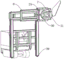
fig. 7 is a schematic view of a headstock structure according to the present invention.
Description of reference numerals:
1. a main chassis; 2. a frame; 3. a first upright post; 4. a second upright post; 5. a first bottom saddle; 6. a second bottom saddle; 7. a headstock; 8. a third slide rail; 9. a second slide rail; 10. a first slide rail; 11. a first adjustment mechanism; 12. a second adjustment mechanism; 13. a third adjustment mechanism; 14. a U-shaped connecting piece; 15. a first inner chamber; 16. a second inner chamber; 17. a first drive motor; 18. a first bevel gear; 19. a second bevel gear; 20. a first gear; 21. a second gear; 22. a third gear; 23. a chain; 24. A pulley; 25. assembling a seat; 26. a working box; 27. a second drive motor; 28. a first threaded rod; 29. A fourth gear; 30. a rotating base; 31. an adjusting frame; 32. a third drive motor; 33. a rotating shaft; 34. rotating the connecting piece; 35. a chain arm saw body; 36. supporting legs; 37. a first ejection cylinder; 38. A second ejection cylinder; 39. a third ejection cylinder; 40. assembling and supporting; 41. a connecting seat.
Detailed Description
In order to make the technical solutions of the present invention better understood, those skilled in the art will now describe the present invention in further detail with reference to the accompanying drawings.
The invention provides an adjustable chain arm saw for a hole as shown in figures 1-7, which comprises a main case 1, wherein a frame 2 is arranged on the front side of the main case 1, first upright posts 3 are symmetrically welded on two sides of the frame 2, second upright posts 4 are welded on one sides of the two first upright posts 3 far away from the frame 2, a first bottom saddle 5 is arranged on one side of the top ends of the two second upright posts 4, a second bottom saddle 6 is arranged on one side of the first bottom saddle 5 far away from the two first upright posts 3, a headstock 7 is arranged on one side of the second bottom saddle 6 far away from the first bottom saddle 5, a first slide rail 10, a second slide rail 9 and a third slide rail 8 are respectively welded on two sides of the second bottom saddle 6, the first bottom saddle 5 and the two second upright posts 4, two first adjusting mechanisms 11 are symmetrically arranged on two ends of the first bottom saddle 5, two second adjusting mechanisms 12 are arranged on one side of one end of the second bottom saddle 6, two third adjusting mechanisms 13 are arranged on one side of one end of the headstock 7, each of the first adjusting mechanism 11, the second adjusting mechanism 12 and the third adjusting mechanism 13 comprises a U-shaped connecting piece 14 welded and fixed with the first bottom saddle 5, the second bottom saddle 6 and the headstock 7, a first inner chamber 15 and a second inner chamber 16 are arranged in one side wall of the U-shaped connecting piece 14, a first driving motor 17 horizontally arranged is arranged in the first inner chamber 15, the output end of the first driving motor 17 is rotatably connected with a first bevel gear 18 through a rotating shaft, the first bevel gear 18 is sequentially engaged and connected with a second bevel gear 19, the center of one side of the bottom of the second bevel gear 19 penetrates through and extends to the second inner chamber 16 and is rotatably connected with a first gear 20 through the rotating shaft, one side of the first gear 20 is provided with a second gear 21, and a plurality of third gears 22 are uniformly arranged between the second gear 21 and the first gear 20, first gear 20, second gear 21 and a plurality of third gear 22 mesh jointly and are connected with chain 23, one side center department of first gear 20, second gear 21 and a plurality of third gear 22 all runs through and extends to and is connected with pulley 24, a plurality of through the pivot rotation in the U type connecting piece 14, pulley 24 respectively with correspond first slide rail 10, second slide rail 9 and third slide rail 8 sliding connection.
Further, in the above technical solution, an assembly seat 25 is welded on one side of the headstock 7 away from the second bottom saddle 6, a working box 26 is welded on one side of the assembly seat 25, a second driving motor 27 vertically arranged is arranged in the working box 26, an output end of the second driving motor 27 is rotatably connected with a first threaded rod 28, one side of the first threaded rod 28 away from the second driving motor 27 is connected with a fourth gear 29 in a meshing manner, a center of one side of the fourth gear 29 penetrates through the working box 26 through a rotating shaft and is connected with a rotating seat 30, the second driving motor 27 drives the first threaded rod 28 to rotate by starting the second driving motor 27, the first threaded rod 28 is rotatably meshed to drive the fourth gear 29 to rotate, the fourth gear 29 rotates to drive the rotating seat 30 to rotate through the rotating shaft, so as to realize multi-angle adjustment of the chain arm saw body 35, the applicability is high.
Further, in the above technical scheme, one side welding that the work box 26 was kept away from to roating seat 30 has an adjusting frame 31, be provided with third driving motor 32 in the adjusting frame 31, the output of third driving motor 32 rotates and is connected with rotation axis 33, the one end welding that rotation axis 33 runs through behind the adjusting frame 31 has a rotation connecting piece 34, one side welding that rotates connecting piece 34 has chain arm saw body 35, through starting third driving motor 32 work for third driving motor 32 drives rotation axis 33 rotatory, and rotation axis 33 rotates and drives connecting piece 34 and rotate and then drive chain arm saw body 35 and adjust, thereby is convenient for realize the position adjustment of chain arm saw body 35.
Further, in the above technical scheme, supporting legs 36 are symmetrically welded at two ends of one side of the bottom of the main case 1, and first ejection cylinders 37 are arranged at the bottom ends of the two supporting legs 36.
Further, in the above technical solution, the top ends of the two second columns 4 are respectively provided with a second ejection cylinder 38, the bottom ends of the two second columns 4 are respectively provided with a third ejection cylinder 39, one side of the main cabinet 1 is provided with an assembly support 40, two ends of one side of the rack 2 are symmetrically provided with connecting seats 41, and each connecting seat 41 is rotatably connected with the assembly support 40 through a rotating shaft.
The working principle of the invention is as follows:
referring to the attached drawings 1-7 in the specification, when a cut needs to be made, firstly, the first adjusting mechanism 11 is started to work, the first driving motor 17 drives the first bevel gear 18 to rotate, the first bevel gear 18 is rotationally engaged to drive the second bevel gear 19 to rotate, the second bevel gear 19 rotates to drive the first gear 20 to rotate through a rotating shaft, the first gear 20 rotates to drive the second gear 21 and the plurality of third gears 22 to rotate through a chain 23, then the first gear 20, the second gear 21 and the plurality of third gears 22 drive the plurality of pulleys 24 to simultaneously rotate through the rotating shaft and slide downwards along the third slide rail 8 until a specified position is reached, when a cut needs to be made, the second adjusting mechanism 12 is started to work firstly, the first driving motor 17 drives the first bevel gear 18 to rotate, the first bevel gear 18 is rotationally engaged to drive the second bevel gear 19 to rotate, the second bevel gear 19 rotates to drive the first gear 20 to rotate through the rotating shaft, the first gear 20 rotates to drive the second gear 21 and the plurality of third gears 22 to rotate through the chain 23, then the first gear 20, the second gear 21 and the plurality of third gears 22 drive the plurality of pulleys 24 to simultaneously rotate through the rotating shaft and slide left and right along the second slide rail 9 until reaching a specified position, further, the third adjusting mechanism 13 is started to work, the first driving motor 17 drives the first bevel gear 18 to rotate, the first bevel gear 18 rotates and is engaged with the second bevel gear 19 to rotate, the second bevel gear 19 rotates to drive the first gear 20 to rotate through the rotating shaft, the first gear 20 rotates to drive the second gear 21 and the plurality of third gears 22 to rotate through the chain 23, then the first gear 20, the second gear 21 and the plurality of third gears 22 drive the plurality of pulleys 24 to simultaneously rotate through the rotating shaft and slide left and right along the first slide rail 10 until reaching the specified position, and the second driving motor 27 is started to work, the second driving motor 27 is enabled to drive the first threaded rod 28 to rotate, the first threaded rod 28 is meshed with the fourth gear 29 in a rotating mode, the fourth gear 29 rotates to drive the rotating seat 30 to rotate through the rotating shaft, the third driving motor 32 is started to work, the third driving motor 32 drives the rotating shaft 33 to rotate, and the rotating shaft 33 rotates to drive the connecting piece 34 to rotate so as to drive the chain arm saw body 35 to adjust.
While certain exemplary embodiments of the present invention have been described above by way of illustration only, it will be apparent to those of ordinary skill in the art that the described embodiments may be modified in various different ways without departing from the spirit and scope of the invention. Accordingly, the drawings and description are illustrative in nature and should not be construed as limiting the scope of the invention.
Claims (7)
1. The utility model provides a hole adopts adjustable chain arm saw, includes mainframe box (1), its characterized in that: the front side of the mainframe box (1) is provided with a rack (2), the bilateral symmetry welding of the rack (2) is provided with first columns (3), two first columns (3) are provided with second columns (4) in the welding manner, one side of the two second columns (4) far away from the rack (2) is provided with a first bottom saddle (5), one side of the first bottom saddle (5) far away from the two first columns (3) is provided with a second bottom saddle (6), one side of the second bottom saddle (6) far away from the first bottom saddle (5) is provided with a headstock (7), the two sides of the second bottom saddle (6), the first bottom saddle (5) and the two second columns (4) are provided with a first slide rail (10), a second slide rail (9) and a third slide rail (8) respectively, two ends of the first bottom saddle (5) are symmetrically provided with two first adjusting mechanisms (11), one side of one end of the second bottom saddle (6) is provided with two second adjusting mechanisms (12), one side of one end of the headstock (7) is provided with two third adjusting mechanisms (13), each of the first adjusting mechanism (11), the second adjusting mechanism (12) and the third adjusting mechanism (13) comprises a U-shaped connecting piece (14) fixedly welded with the first bottom saddle (5), the second bottom saddle (6) and the headstock (7), a first inner chamber (15) and a second inner chamber (16) are arranged in one side wall of the U-shaped connecting piece (14), a first driving motor (17) horizontally arranged is arranged in the first inner chamber (15), the output end of the first driving motor (17) is rotatably connected with a first bevel gear (18) through a rotating shaft, the first bevel gear (18) is sequentially meshed with a second bevel gear (19), and the center of one side of the bottom of the second bevel gear (19) penetrates through and extends to the second inner chamber (16) through a rotating shaft The axle rotates and is connected with first gear (20), one side of first gear (20) is equipped with second gear (21), evenly be equipped with a plurality of third gear (22) between second gear (21) and first gear (20), second gear (21) and a plurality of third gear (22) mesh jointly and are connected with chain (23), one side center department of first gear (20), second gear (21) and a plurality of third gear (22) all runs through and extends to and be connected with pulley (24) through the pivot rotation in U type connecting piece (14), and is a plurality of pulley (24) respectively with correspond first slide rail (10), second slide rail (9) and third slide rail (8) sliding connection.
2. A hole saw adjustable chain arm as claimed in claim 1, wherein: one side welding that second end saddle (6) was kept away from in headstock (7) has assembly seat (25), one side welding of assembly seat (25) has work box (26), be provided with in work box (26) and be second driving motor (27) of perpendicular setting, the output of second driving motor (27) is rotated and is connected with first threaded rod (28), the one end one side meshing that second driving motor (27) were kept away from in first threaded rod (28) is connected with fourth gear (29), one side center department of fourth gear (29) is connected with roating seat (30) through pivot after running through work box (26).
3. A hole saw as defined in claim 2, wherein: one side welding that work box (26) was kept away from in roating seat (30) has adjusting frame (31), be provided with third driving motor (32) in adjusting frame (31), the output of third driving motor (32) is rotated and is connected with rotation axis (33), the one end welding that rotation axis (33) run through behind adjusting frame (31) has rotation connecting piece (34), the one side welding that rotates connecting piece (34) has chain arm saw body (35).
4. A hole saw adjustable chain arm as claimed in claim 1, wherein: the bottom of mainframe box (1) one side both ends symmetry welding have supporting leg (36), two the bottom of supporting leg (36) all is equipped with first ejecting hydro-cylinder (37).
5. A hole saw as defined in claim 4, wherein: and the top ends of the two second upright columns (4) are respectively provided with a second ejection oil cylinder (38), and the bottom ends of the two second upright columns (4) are respectively provided with a third ejection oil cylinder (39).
6. A hole saw as defined in claim 5, wherein: one side of the mainframe box (1) is provided with an assembly support (40).
7. A hole saw as defined in claim 6, wherein: and two ends of one side of the rack (2) are symmetrically provided with connecting seats (41), and each connecting seat (41) is rotatably connected with the assembly support (40) through a rotating shaft.
Priority Applications (1)
| Application Number | Priority Date | Filing Date | Title |
|---|---|---|---|
| CN202011264081.8A CN112405882A (en) | 2020-11-12 | 2020-11-12 | Hole-adopted adjustable chain arm saw |
Applications Claiming Priority (1)
| Application Number | Priority Date | Filing Date | Title |
|---|---|---|---|
| CN202011264081.8A CN112405882A (en) | 2020-11-12 | 2020-11-12 | Hole-adopted adjustable chain arm saw |
Publications (1)
| Publication Number | Publication Date |
|---|---|
| CN112405882A true CN112405882A (en) | 2021-02-26 |
Family
ID=74831049
Family Applications (1)
| Application Number | Title | Priority Date | Filing Date |
|---|---|---|---|
| CN202011264081.8A Pending CN112405882A (en) | 2020-11-12 | 2020-11-12 | Hole-adopted adjustable chain arm saw |
Country Status (1)
| Country | Link |
|---|---|
| CN (1) | CN112405882A (en) |
-
2020
- 2020-11-12 CN CN202011264081.8A patent/CN112405882A/en active Pending
Similar Documents
| Publication | Publication Date | Title |
|---|---|---|
| CN113290186B (en) | Cold header | |
| CN103240463A (en) | Special sawing machine for large members | |
| CN202318605U (en) | Horizontal stone material rotary cutting machine | |
| CN112355674A (en) | Multipurpose sawing machine fixture | |
| CN106736741A (en) | A kind of jig for cylindric workpiece | |
| CN210237445U (en) | Multifunctional glass cutting machine | |
| CN108890202B (en) | Welding bench fixing and clamping device for building | |
| CN213890688U (en) | Hole-adopted adjustable chain arm saw | |
| CN112405882A (en) | Hole-adopted adjustable chain arm saw | |
| CN203109757U (en) | Special machining machine tool for numerical-control full-automatic cam | |
| CN208615068U (en) | A kind of graphite crucible automatic porous drilling machine | |
| CN206912404U (en) | A kind of gear-hobbing machine burr remover | |
| CN210633031U (en) | High-efficient large-scale band sawing machine | |
| KR101129066B1 (en) | Apparatus for multi wood processing machine | |
| CN102179841B (en) | Multi-station vertical type band sawing machine tool with pneumatic clamping wood and method for installing pneumatic clamping wood | |
| CN204868446U (en) | A revolve column type sideslip grinding device for processing stone pillar | |
| CN205166606U (en) | A hanging sideslip device that grinds soon for processing stone pillar | |
| CN205033047U (en) | A although chain is revolved post is moved adjustable grinding device for processing stone pillar | |
| CN209887107U (en) | Vertical elevating platform milling machine is used in processing of iron fitting-out spare | |
| CN210633262U (en) | Dual-purpose device for drilling and polishing bearing seat | |
| CN207841787U (en) | Horizontal multitool is same to cut a seam material cutting machine | |
| CN206335357U (en) | A kind of high speed drill attacks processing center machine tool | |
| CN208019595U (en) | A kind of workpiece guided cutting apparatus | |
| CN206306216U (en) | A kind of Tenon machine of comprehensive processing | |
| CN215618638U (en) | Coping saw instrument platform |
Legal Events
| Date | Code | Title | Description |
|---|---|---|---|
| PB01 | Publication | ||
| PB01 | Publication | ||
| SE01 | Entry into force of request for substantive examination | ||
| SE01 | Entry into force of request for substantive examination |