CN112400665A - Water-saving and water-spraying control device for landscaping - Google Patents
Water-saving and water-spraying control device for landscaping Download PDFInfo
- Publication number
- CN112400665A CN112400665A CN202011407011.3A CN202011407011A CN112400665A CN 112400665 A CN112400665 A CN 112400665A CN 202011407011 A CN202011407011 A CN 202011407011A CN 112400665 A CN112400665 A CN 112400665A
- Authority
- CN
- China
- Prior art keywords
- water
- fixedly arranged
- water tank
- landscaping
- control device
- Prior art date
- Legal status (The legal status is an assumption and is not a legal conclusion. Google has not performed a legal analysis and makes no representation as to the accuracy of the status listed.)
- Withdrawn
Links
Images


Classifications
-
- A—HUMAN NECESSITIES
- A01—AGRICULTURE; FORESTRY; ANIMAL HUSBANDRY; HUNTING; TRAPPING; FISHING
- A01G—HORTICULTURE; CULTIVATION OF VEGETABLES, FLOWERS, RICE, FRUIT, VINES, HOPS OR SEAWEED; FORESTRY; WATERING
- A01G25/00—Watering gardens, fields, sports grounds or the like
- A01G25/02—Watering arrangements located above the soil which make use of perforated pipe-lines or pipe-lines with dispensing fittings, e.g. for drip irrigation
-
- C—CHEMISTRY; METALLURGY
- C02—TREATMENT OF WATER, WASTE WATER, SEWAGE, OR SLUDGE
- C02F—TREATMENT OF WATER, WASTE WATER, SEWAGE, OR SLUDGE
- C02F9/00—Multistage treatment of water, waste water or sewage
-
- E—FIXED CONSTRUCTIONS
- E03—WATER SUPPLY; SEWERAGE
- E03B—INSTALLATIONS OR METHODS FOR OBTAINING, COLLECTING, OR DISTRIBUTING WATER
- E03B3/00—Methods or installations for obtaining or collecting drinking water or tap water
- E03B3/02—Methods or installations for obtaining or collecting drinking water or tap water from rain-water
-
- C—CHEMISTRY; METALLURGY
- C02—TREATMENT OF WATER, WASTE WATER, SEWAGE, OR SLUDGE
- C02F—TREATMENT OF WATER, WASTE WATER, SEWAGE, OR SLUDGE
- C02F1/00—Treatment of water, waste water, or sewage
- C02F1/001—Processes for the treatment of water whereby the filtration technique is of importance
-
- C—CHEMISTRY; METALLURGY
- C02—TREATMENT OF WATER, WASTE WATER, SEWAGE, OR SLUDGE
- C02F—TREATMENT OF WATER, WASTE WATER, SEWAGE, OR SLUDGE
- C02F1/00—Treatment of water, waste water, or sewage
- C02F1/28—Treatment of water, waste water, or sewage by sorption
- C02F1/283—Treatment of water, waste water, or sewage by sorption using coal, charred products, or inorganic mixtures containing them
-
- C—CHEMISTRY; METALLURGY
- C02—TREATMENT OF WATER, WASTE WATER, SEWAGE, OR SLUDGE
- C02F—TREATMENT OF WATER, WASTE WATER, SEWAGE, OR SLUDGE
- C02F2103/00—Nature of the water, waste water, sewage or sludge to be treated
- C02F2103/001—Runoff or storm water
-
- C—CHEMISTRY; METALLURGY
- C02—TREATMENT OF WATER, WASTE WATER, SEWAGE, OR SLUDGE
- C02F—TREATMENT OF WATER, WASTE WATER, SEWAGE, OR SLUDGE
- C02F2301/00—General aspects of water treatment
- C02F2301/08—Multistage treatments, e.g. repetition of the same process step under different conditions
-
- Y—GENERAL TAGGING OF NEW TECHNOLOGICAL DEVELOPMENTS; GENERAL TAGGING OF CROSS-SECTIONAL TECHNOLOGIES SPANNING OVER SEVERAL SECTIONS OF THE IPC; TECHNICAL SUBJECTS COVERED BY FORMER USPC CROSS-REFERENCE ART COLLECTIONS [XRACs] AND DIGESTS
- Y02—TECHNOLOGIES OR APPLICATIONS FOR MITIGATION OR ADAPTATION AGAINST CLIMATE CHANGE
- Y02A—TECHNOLOGIES FOR ADAPTATION TO CLIMATE CHANGE
- Y02A20/00—Water conservation; Efficient water supply; Efficient water use
- Y02A20/108—Rainwater harvesting
Abstract
The invention relates to the technical field of landscaping, in particular to a water-saving water spray control device for landscaping. The water catch bowl and the through-hole of water tank top can be collected the rainwater, the filter screen can play filterable effect to the rainwater, purifier can play the effect that the purification peculiar smell was got rid of to the rainwater, elevating gear can play the effect of adjusting to the height of shower nozzle, the device that sways simultaneously can drive the direction of shower nozzle, realize the change of angle, thereby realize the rotation of multi-angle, increase the area of spouting, the effectual work efficiency who sprays that has improved, the device simple structure, convenient operation and use, staff's intensity of labour has been reduced, great improvement work efficiency.
Description
Technical Field
The invention relates to the technical field of landscaping, in particular to a water-saving water spray control device for landscaping.
Background
Landscaping refers to the creation of beautiful natural environment and rest area by reforming terrain (or further building mountain, stacking stone, managing water) to plant trees and flowers, building buildings and arranging garden paths, etc., and is called garden. Gardens include gardens, residential gardens, small paradises, gardens, parks, vegetable gardens, zoos and the like, and with the development of the garden discipline, forest parks, scenic spots, natural conservation areas or tourist areas of national parks and recreational areas are included.
Most of water used for greening by the existing greening water spraying device is drinkable water, and certain waste is caused to the use of water resources. The afforestation in gardens adopts the gardener to carry on one's back the bucket and hold the shower nozzle and spray mostly, and the shower nozzle can be in the water spray that does not stop like this, and it is extremely low to cause very big waste to spray efficiency simultaneously.
Therefore, those skilled in the art provide a water-saving spraying control device for landscaping to solve the problems set forth in the background art.
Disclosure of Invention
The invention aims to provide a water-saving water spraying control device for landscaping, which aims to solve the problems in the background technology.
In order to achieve the purpose, the invention provides the following technical scheme: a water-saving and water-spraying control device for landscaping comprises a base, wherein a water tank is fixedly arranged on one side of the base, a purification device is arranged inside the water tank, a filtering device is arranged above the water tank, a water pump is fixedly arranged on one side of the water tank and positioned on the base, one end of the water pump is communicated with the water tank through a communicating pipe, a hose is arranged at the other end of the water pump, a spray head is arranged at the other end of the hose, the spray head is connected with a swinging device, and one side of the swinging device is connected with a lifting device;
a water collecting tank is arranged at the top of the filtering device, a plurality of through holes are formed in the water collecting tank, a filter screen is arranged on one side above the water collecting tank, first fixing rods are fixedly arranged on two sides of one end of the filter screen, second fixing rods are fixedly arranged on two sides of the other end of the filter screen, and the other ends of the first fixing rods and the second fixing rods are fixedly connected with the edge of the water tank;
the purification device comprises a filter plate fixedly arranged in the water tank, a cavity is arranged in the filter plate, a sandstone layer is arranged in the cavity, and an activated carbon adsorption plate is fixedly arranged on one side below the filter plate and positioned in the water tank;
the lifting device comprises a first sliding groove fixedly arranged on one side of the base, a threaded rod is fixedly arranged inside the first sliding groove, a nut is arranged on the threaded rod in a threaded manner, one end of the threaded rod penetrates through the first sliding groove and extends towards the inside of the placing groove, the placing groove is provided with the inside of the base, a first motor is fixedly arranged inside the placing groove, and the output end of the first motor is fixedly connected with one end of the threaded rod;
the swinging device comprises a fixed box, a transverse plate is fixedly arranged on one side of the fixed box, a rotary table is arranged above one side of the transverse plate, a swinging rod is arranged on one side, away from the transverse plate, of the rotary table, a pushing groove is formed in the middle of the swinging rod, a fixed pin is fixedly arranged in the pushing groove and positioned at the eccentric position of the rotary table, a fixed block is fixedly arranged at one end of the swinging rod, the spray head penetrates through the middle of the fixed block, the joint of the fixed block and the swinging rod is movably connected with the transverse plate through a movable pin, and one side of the middle of the rotary table is connected with a power device;
the power device is including fixing to be located the pivot of carousel below one side, the pivot runs through the diaphragm just extends to its below and is connected with first belt pulley, one side of first belt pulley just is located the inside of fixed case is equipped with the second belt pulley, one side of second belt pulley is connected with the output of second motor, the opening has been seted up to one side of fixed case, first belt pulley with connect through the belt between the second belt pulley.
As a further aspect of the invention: one side installation piece of fixed case with one side fixed connection of nut, one side that fixed case kept away from the nut is equipped with stop device.
As a further aspect of the invention: the limiting device comprises a connecting block fixedly arranged on one side of the fixed box, a sliding block is fixedly arranged on the other side of the connecting block, one side of the sliding block is arranged in the second sliding groove, and one end of the second sliding groove is fixedly arranged on one side of the base.
As a further aspect of the invention: the first spout with fixedly between the second spout be equipped with the waterproof box, the inside of waterproof box is equipped with the battery, the battery respectively with water pump, first motor and second motor electric connection.
As a further aspect of the invention: one side of the base, which is far away from the water tank, is fixedly provided with four moving wheels, and the moving wheels are fixedly connected with the base in a rectangular array mode.
As a further aspect of the invention: the fixed support column that is equipped with in below one side of filter plate, the other end of support column runs through activated carbon adsorption plate just extends to its below and the bottom fixed connection of water tank.
As a further aspect of the invention: and damping springs are sleeved on the threaded rods on two sides of the nuts.
As a further aspect of the invention: and a drain pipe is arranged on one side of the water tank, one end of the drain pipe is communicated with the water tank, and a control valve is arranged at the other end of the drain pipe.
As a further aspect of the invention: the middle of the fixed block is provided with a mounting hole, and the spray head is arranged inside the mounting hole.
Compared with the prior art, the invention has the beneficial effects that: in rainy weather, the water catch bowl of water tank top can be collected the rainwater, and flow in the inside of water tank from the through-hole, the filter screen can play filterable effect to the rainwater, purifier can play the effect that the purification peculiar smell got rid of to the rainwater, elevating gear can play the effect of adjusting to the height of shower nozzle, the device that sways simultaneously can drive the direction of shower nozzle, realize the change of angle, thereby realize the rotation of multi-angle, increase the area that scatters, the effectual work efficiency that improves spraying, the device simple structure, facilitate the operation and use, staff's intensity of labour has been reduced, great improvement work efficiency.
Drawings
FIG. 1 is a schematic structural view of a water-saving spray control device for landscaping;
FIG. 2 is a sectional view of a water-saving spray control device for landscaping;
FIG. 3 is a sectional view of a water tank of a water saving spray control device for landscaping;
FIG. 4 is a schematic structural view of a lifting device in the water-saving spray control device for landscaping;
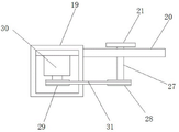
FIG. 5 is a schematic structural view of a swing device in the water-saving spray control device for landscaping;
fig. 6 is a schematic structural view of a fixing tank in the water-saving spray control device for landscaping.
In the figure: 1. a base; 2. a water tank; 3. a water pump; 4. a hose; 5. a spray head; 6. a swing device; 7. a water collection tank; 8. a filter screen; 9. a first fixing lever; 10. a second fixing bar; 11. filtering the plate; 12. a sandstone layer; 13. an activated carbon adsorption plate; 14. a first chute; 15. a threaded rod; 16. a nut; 17. a placement groove; 18. a first motor; 19. a fixed box; 20. a transverse plate; 21. a turntable; 22. a swing rod; 23. pushing the groove; 24. a fixing pin; 25. a fixed block; 26. a movable pin; 27. a rotating shaft; 28. a first pulley; 29. a second pulley; 30. a second motor; 31. a belt; 32. a slider; 33. a second chute; 34. a storage battery; 35. a moving wheel; 36. and (4) a support column.
Detailed Description
Referring to fig. 1-6, in the embodiment of the invention, a water-saving and water-spraying control device for landscaping comprises a base 1, a water tank 2 is fixedly arranged on one side of the base 1, a purification device is arranged inside the water tank 2, a filter device is arranged above the water tank 2, a water pump 3 is fixedly arranged on one side of the water tank 2 and positioned on the base 1, one end of the water pump 3 is communicated with the water tank 2 through a communicating pipe, a hose 4 is arranged on the other end of the water pump 3, a spray head 5 is arranged on the other end of the hose 4, the spray head 5 is connected with a swing device 6, and one side of the;
in fig. 1, 2 and 3: a water collecting tank 7 is arranged at the top of the filtering device, a plurality of through holes are formed in the water collecting tank 7, a filter screen 8 is arranged on one side above the water collecting tank 7, first fixing rods 9 are fixedly arranged on two sides of one end of the filter screen 8, second fixing rods 10 are fixedly arranged on two sides of the other end of the filter screen 8, and the other ends of the first fixing rods 9 and the second fixing rods 10 are fixedly connected with the edge of the water tank 2;
in fig. 2 and 3: the purification device comprises a filter plate 11 fixedly arranged in the water tank 2, a cavity is arranged in the filter plate 11, a sandstone layer 12 is arranged in the cavity, and an activated carbon adsorption plate 13 is fixedly arranged on one side below the filter plate 11 and positioned in the water tank 2;
in fig. 2 and 4: the lifting device comprises a first sliding chute 14 fixedly arranged on one side of the base 1, a threaded rod 15 is fixedly arranged inside the first sliding chute 14, a nut 16 is arranged on the threaded rod 15 in a threaded manner, one end of the threaded rod 15 penetrates through the first sliding chute and extends towards the inside of the placing groove 17, the placing groove 17 is provided with the inside of the base 1, a first motor 18 is fixedly arranged inside the placing groove 17, and the output end of the first motor 18 is fixedly connected with one end of the threaded rod 15;
in fig. 1 and 5: the swinging device comprises a fixed box 19, a transverse plate 20 is fixedly arranged on one side of the fixed box 19, a rotary plate 21 is arranged above one side of the transverse plate 20, a swing rod 22 is arranged on one side, away from the transverse plate 20, of the rotary plate 21, a push groove 23 is formed in the middle of the swing rod 22, a fixed pin 24 is fixedly arranged in the push groove 23 and positioned at the eccentric position of the rotary plate 21, a fixed block 25 is fixedly arranged at one end of the swing rod 22, a spray head 5 is arranged in the middle of the fixed block 25 in a penetrating mode, the connecting position of the fixed block 25 and the swing rod 22 is movably connected with the transverse plate 20 through a;
in FIG. 6: power device is including fixed pivot 27 of locating carousel 21 below one side, and pivot 27 runs through diaphragm 20 just extends to its below and is connected with first belt pulley 28, and one side of first belt pulley 28 and the inside that is located fixed case 19 are equipped with second belt pulley 29, and one side of second belt pulley 29 is connected with the output of second motor 30, and the opening has been seted up to one side of fixed case 19, connects through belt 31 between first belt pulley 28 and the second belt pulley 29.
In FIG. 4: one side installation piece of fixed case 19 is connected with one side fixed connection of nut 16, and one side that fixed case 19 kept away from nut 16 is equipped with stop device, makes things convenient for the connection between fixed case 19 and the nut 16.
In fig. 1 and 4: stop device is including the fixed connecting block of locating fixed case 19 one side, and the fixed slider 32 that is equipped with of opposite side of connecting block, and the inside of second spout 33 is located to one side of slider 32, and the one end of second spout 33 is fixed and is located base 1 one side, increases the stability of fixed case 19 lift in-process.
In FIG. 4: the waterproof box is fixedly arranged between the first sliding groove 14 and the second sliding groove 33, the storage battery 34 is arranged inside the waterproof box, the storage battery 34 is respectively electrically connected with the water pump 3, the first motor 18 and the second motor 30, electric energy can be provided for the water pump 3, the first motor 18 and the second motor 30, and the use convenience is improved.
In FIG. 2: one side that water tank 2 was kept away from to base 1 is fixed to be equipped with quantity and is four removal wheel 35, removes wheel 35 and base 1 fixed connection with the form of rectangle permutation, increases the convenience that base 1 removed.
In FIG. 2: the fixed support column 36 that is equipped with in below one side of filter plate 11, the other end of support column 36 run through activated carbon adsorption plate 13 and extend to its below and water tank 2's bottom fixed connection, can play the effect of support to filter plate 11, have increased the security that filter plate 11 placed.
In fig. 2 and 4: both sides of nut 16 just are located threaded rod 15 and all overlap and are equipped with damping spring, can start absorbing effect to nut 16, have increased the security of using.
In fig. 1: one side of water tank 2 is equipped with the drain pipe, and drain pipe one end is linked together with water tank 2, and the other end of drain pipe is equipped with the control valve, conveniently discharges the washing to the water in the water tank 2.
In FIG. 5: the middle of fixed block 25 is equipped with the mounting hole, and the inside of mounting hole is located to shower nozzle 5, the convenient installation to shower nozzle 5.
The working principle of the invention is as follows: in particular use, in rainy days, the water collecting tank 7 above the water tank 2 can collect rainwater and flow into the water tank 2 from the through hole, the filter screen 8 can filter the rainwater and can filter impurities in the rainwater, then the rainwater is subjected to a sand-stone layer to filter fine particles in the rainwater, then the activated carbon adsorption plate 13 removes peculiar smell in the rainwater, so that rainwater purification can be realized, then the water pump 3 is started, the water in the water tank 2 can be conveyed to the spray head 5 through the communicating pipe through the hose 4 and then is sprayed out by the spray head 5, the second motor 30 is started in the spraying process, the second motor 30 is started to drive the second belt pulley 29 to rotate, the second belt pulley 29 is rotated to drive the first belt pulley 28 to rotate through the belt 31, the first belt pulley 28 is rotated to drive the rotation of the rotating disc 21 through the rotating shaft 27, the rotation of the rotary table 21 drives the fixed pin 24 to move, the fixed pin 24 rotates to push the push groove 23, the push groove 23 moves to drive the swing rod 22 to rotate around the movable pin 26, so as to realize the rotation of the fixed block 25, the fixed block 25 rotates to drive the spray head 5 to rotate, so as to realize the multi-angle rotation, the spraying area is increased, the spraying work efficiency is effectively improved, then the height of the spray head 5 is adjusted through the lifting device, the first motor 18 is started to drive the threaded rod 15 to rotate, the threaded rod 15 rotates to drive the nut 16 to lift, so as to realize the lifting of the fixed box 19, the fixed box 19 drives the swinging device to lift, so as to realize the lifting of the spray head 5, the height adjustment of the spray head 5 is realized, the device has a simple structure, is convenient to operate and use, and reduces the labor intensity of workers, the working efficiency is greatly improved.
The above description is only for the preferred embodiment of the present invention, but the scope of the present invention is not limited thereto, and any person skilled in the art should be considered to be within the technical scope of the present invention, and the technical solutions and the inventive concepts thereof according to the present invention are equivalent to or changed within the technical scope of the present invention.
Claims (9)
1. A water-saving and water-spraying control device for landscaping comprises a base (1) and is characterized in that a water tank (2) is fixedly arranged on one side of the base (1), a purification device is arranged inside the water tank (2), a filtering device is arranged above the water tank (2), a water pump (3) is fixedly arranged on one side of the water tank (2) and positioned on the base (1), one end of the water pump (3) is communicated with the water tank (2) through a communicating pipe, a hose (4) is arranged at the other end of the water pump (3), a spray head (5) is arranged at the other end of the hose (4), the spray head (5) is connected with a swinging device (6), and one side of the swinging device is connected with a lifting device;
a water collecting tank (7) is formed in the top of the filtering device, a plurality of through holes are formed in the water collecting tank (7), a filter screen (8) is arranged on one side above the water collecting tank (7), first fixing rods (9) are fixedly arranged on two sides of one end of the filter screen (8), second fixing rods (10) are fixedly arranged on two sides of the other end of the filter screen (8), and the other ends of the first fixing rods (9) and the second fixing rods (10) are fixedly connected with the edge of the water tank (2);
the purification device comprises a filter plate (11) fixedly arranged in the water tank (2), a cavity is arranged in the filter plate (11), a sandstone layer (12) is arranged in the cavity, and an activated carbon adsorption plate (13) is fixedly arranged on one side below the filter plate (11) and positioned in the water tank (2);
the lifting device comprises a first sliding chute (14) fixedly arranged on one side of the base (1), a threaded rod (15) is fixedly arranged inside the first sliding chute (14), a nut (16) is arranged on the threaded rod (15) in a threaded manner, one end of the threaded rod (15) penetrates through the first sliding chute and extends towards the inside of the placing groove (17), the placing groove (17) is provided with the inside of the base (1), a first motor (18) is fixedly arranged inside the placing groove (17), and the output end of the first motor (18) is fixedly connected with one end of the threaded rod (15);
the swinging device comprises a fixed box (19), a transverse plate (20) is fixedly arranged on one side of the fixed box (19), a rotary plate (21) is arranged above one side of the transverse plate (20), a swinging rod (22) is arranged on one side, away from the transverse plate (20), of the rotary plate (21), a pushing groove (23) is formed in the middle of the swinging rod (22), a fixing pin (24) is fixedly arranged in the pushing groove (23) and positioned at the eccentric position of the rotary plate (21), a fixing block (25) is fixedly arranged at one end of the swinging rod (22), the spray head (5) penetrates through the middle of the fixing block (25), the connecting position of the fixing block (25) and the swinging rod (22) is movably connected with the transverse plate (20) through a movable pin (26), and one side of the middle of the rotary plate (21) is connected with a power device;
the power device is including fixed locating pivot (27) of carousel (21) below one side, pivot (27) run through diaphragm (20) and extend to its below and be connected with first belt pulley (28), one side of first belt pulley (28) just is located the inside of fixed case (19) is equipped with second belt pulley (29), one side of second belt pulley (29) is connected with the output of second motor (30), the opening has been seted up to one side of fixed case (19), first belt pulley (28) with connect through belt (31) between second belt pulley (29).
2. The water-saving spraying control device for the landscaping as claimed in claim 1, wherein a side mounting block of the fixing box (19) is fixedly connected with one side of the nut (16), and a side of the fixing box (19) far away from the nut (16) is provided with a limiting device.
3. The water-saving spraying control device for landscaping as claimed in claim 2, wherein the limiting device comprises a connecting block fixedly arranged on one side of the fixed box (19), a sliding block (32) is fixedly arranged on the other side of the connecting block, one side of the sliding block (32) is arranged inside the second sliding groove (33), and one end of the second sliding groove (33) is fixedly arranged on one side of the base (1).
4. A water-saving spraying control device for garden greening according to claim 3, characterized in that a waterproof box is fixedly arranged between the first chute (14) and the second chute (33), a storage battery (34) is arranged in the waterproof box, and the storage battery (34) is electrically connected with the water pump (3), the first motor (18) and the second motor (30) respectively.
5. A water-saving water spray control device for landscaping, as claimed in claim 1, wherein a side of the base (1) away from the water tank (2) is fixedly provided with four moving wheels (35), and the moving wheels (35) are fixedly connected with the base (1) in a rectangular array.
6. The water-saving spraying control device for the landscaping as claimed in claim 1, wherein a support column (36) is fixedly arranged at one side below the filter plate (11), and the other end of the support column (36) penetrates through the activated carbon adsorption plate (13) and extends below the activated carbon adsorption plate to be fixedly connected with the bottom of the water tank (2).
7. The water-saving spraying control device for the landscaping as claimed in claim 1, wherein damping springs are sleeved on the threaded rods (15) and on both sides of the nuts (16).
8. A water-saving water spray control device for landscaping, as claimed in claim 1, wherein a drain pipe is provided at one side of the water tank (2), one end of the drain pipe is connected to the water tank (2), and a control valve is provided at the other end of the drain pipe.
9. A water-saving water spray control device for landscaping, as claimed in claim 1, wherein a mounting hole is provided in the middle of the fixed block (25), and the spray head (5) is provided inside the mounting hole.
Priority Applications (1)
| Application Number | Priority Date | Filing Date | Title |
|---|---|---|---|
| CN202011407011.3A CN112400665A (en) | 2020-12-04 | 2020-12-04 | Water-saving and water-spraying control device for landscaping |
Applications Claiming Priority (1)
| Application Number | Priority Date | Filing Date | Title |
|---|---|---|---|
| CN202011407011.3A CN112400665A (en) | 2020-12-04 | 2020-12-04 | Water-saving and water-spraying control device for landscaping |
Publications (1)
| Publication Number | Publication Date |
|---|---|
| CN112400665A true CN112400665A (en) | 2021-02-26 |
Family
ID=74829169
Family Applications (1)
| Application Number | Title | Priority Date | Filing Date |
|---|---|---|---|
| CN202011407011.3A Withdrawn CN112400665A (en) | 2020-12-04 | 2020-12-04 | Water-saving and water-spraying control device for landscaping |
Country Status (1)
| Country | Link |
|---|---|
| CN (1) | CN112400665A (en) |
Cited By (2)
| Publication number | Priority date | Publication date | Assignee | Title |
|---|---|---|---|---|
| CN114391455A (en) * | 2021-12-06 | 2022-04-26 | 浡江生态建设集团有限公司 | A intelligent watering device for afforestation engineering |
| CN115024197A (en) * | 2022-06-20 | 2022-09-09 | 南通沪望塑料科技发展有限公司 | A water saving fixtures for municipal afforestation construction |
-
2020
- 2020-12-04 CN CN202011407011.3A patent/CN112400665A/en not_active Withdrawn
Cited By (2)
| Publication number | Priority date | Publication date | Assignee | Title |
|---|---|---|---|---|
| CN114391455A (en) * | 2021-12-06 | 2022-04-26 | 浡江生态建设集团有限公司 | A intelligent watering device for afforestation engineering |
| CN115024197A (en) * | 2022-06-20 | 2022-09-09 | 南通沪望塑料科技发展有限公司 | A water saving fixtures for municipal afforestation construction |
Similar Documents
| Publication | Publication Date | Title |
|---|---|---|
| CN112400665A (en) | Water-saving and water-spraying control device for landscaping | |
| CN209403228U (en) | A kind of Collection utilization device of skyscraper rainwater | |
| CN211482111U (en) | Energy-saving roof of green building | |
| CN108901768A (en) | A kind of environment-friendly type treegarden irrigation device | |
| CN211020348U (en) | Irrigation equipment for landscaping maintenance | |
| CN106258827A (en) | A kind of gardens rainwater-collecting flusher | |
| CN112275477B (en) | Drip irrigation device based on afforestation construction and maintenance | |
| CN210382052U (en) | Greening system for ecological roof | |
| CN216973232U (en) | Movable road greening isolation fence | |
| CN213127453U (en) | A ecological slope of forest garden design for protecting plant | |
| CN212013942U (en) | Afforestation watering device | |
| CN211861353U (en) | Afforestation water-saving irrigation system | |
| CN209185277U (en) | The dedicated intelligent water-saving irrigation rig of afforestation | |
| CN211185287U (en) | Low-carbon environment-friendly landscaping device | |
| CN210315330U (en) | Multifunctional guardrail for pedestrian road | |
| CN207355129U (en) | A kind of modular greening wall | |
| CN209435947U (en) | A kind of environment-friendly engineering treegarden irrigation device | |
| CN208650579U (en) | Multifunctional landscape facility suitable for south | |
| CN215454479U (en) | Afforestation spray set based on ecological environment uses | |
| CN2877264Y (en) | Automatic water storing device for flower bed | |
| CN212294833U (en) | Rainwater collection device for municipal works | |
| CN211745968U (en) | Water-saving and water-spraying control device for landscaping | |
| CN220458030U (en) | Ecological garden water saving fixtures | |
| CN218573170U (en) | Multifunctional water spraying device for dust fall, water spraying and slope watering of expressway construction sidewalk | |
| CN216339815U (en) | Afforestation water storage device |
Legal Events
| Date | Code | Title | Description |
|---|---|---|---|
| PB01 | Publication | ||
| PB01 | Publication | ||
| SE01 | Entry into force of request for substantive examination | ||
| SE01 | Entry into force of request for substantive examination | ||
| WW01 | Invention patent application withdrawn after publication | ||
| WW01 | Invention patent application withdrawn after publication |
Application publication date: 20210226 |