CN112394781A - Server and data center with same - Google Patents
Server and data center with same Download PDFInfo
- Publication number
- CN112394781A CN112394781A CN202011306193.5A CN202011306193A CN112394781A CN 112394781 A CN112394781 A CN 112394781A CN 202011306193 A CN202011306193 A CN 202011306193A CN 112394781 A CN112394781 A CN 112394781A
- Authority
- CN
- China
- Prior art keywords
- fan
- module
- board
- power
- accommodating space
- Prior art date
- Legal status (The legal status is an assumption and is not a legal conclusion. Google has not performed a legal analysis and makes no representation as to the accuracy of the status listed.)
- Pending
Links
- 238000005192 partition Methods 0.000 claims description 12
- 230000005611 electricity Effects 0.000 claims description 6
- 238000003780 insertion Methods 0.000 claims description 3
- 230000037431 insertion Effects 0.000 claims description 3
- 229910000831 Steel Inorganic materials 0.000 abstract description 5
- 238000009863 impact test Methods 0.000 abstract description 5
- 239000010959 steel Substances 0.000 abstract description 5
- 238000010586 diagram Methods 0.000 description 7
- 230000004308 accommodation Effects 0.000 description 4
- 238000009434 installation Methods 0.000 description 4
- 238000012423 maintenance Methods 0.000 description 4
- PCHJSUWPFVWCPO-UHFFFAOYSA-N gold Chemical compound [Au] PCHJSUWPFVWCPO-UHFFFAOYSA-N 0.000 description 3
- 229910052737 gold Inorganic materials 0.000 description 3
- 239000010931 gold Substances 0.000 description 3
- RYGMFSIKBFXOCR-UHFFFAOYSA-N Copper Chemical compound [Cu] RYGMFSIKBFXOCR-UHFFFAOYSA-N 0.000 description 2
- 229910052802 copper Inorganic materials 0.000 description 2
- 239000010949 copper Substances 0.000 description 2
- 238000013461 design Methods 0.000 description 2
- 238000000034 method Methods 0.000 description 2
- 230000008569 process Effects 0.000 description 2
- 230000002159 abnormal effect Effects 0.000 description 1
- 230000004075 alteration Effects 0.000 description 1
- 238000010276 construction Methods 0.000 description 1
- 230000000694 effects Effects 0.000 description 1
- 230000017525 heat dissipation Effects 0.000 description 1
- 230000001771 impaired effect Effects 0.000 description 1
- 238000002955 isolation Methods 0.000 description 1
- 239000000463 material Substances 0.000 description 1
- 230000007246 mechanism Effects 0.000 description 1
- 238000012986 modification Methods 0.000 description 1
- 230000004048 modification Effects 0.000 description 1
- 238000006467 substitution reaction Methods 0.000 description 1
Images


Classifications
-
- G—PHYSICS
- G06—COMPUTING; CALCULATING OR COUNTING
- G06F—ELECTRIC DIGITAL DATA PROCESSING
- G06F1/00—Details not covered by groups G06F3/00 - G06F13/00 and G06F21/00
- G06F1/16—Constructional details or arrangements
- G06F1/18—Packaging or power distribution
- G06F1/181—Enclosures
-
- G—PHYSICS
- G06—COMPUTING; CALCULATING OR COUNTING
- G06F—ELECTRIC DIGITAL DATA PROCESSING
- G06F1/00—Details not covered by groups G06F3/00 - G06F13/00 and G06F21/00
- G06F1/16—Constructional details or arrangements
- G06F1/18—Packaging or power distribution
- G06F1/183—Internal mounting support structures, e.g. for printed circuit boards, internal connecting means
- G06F1/185—Mounting of expansion boards
-
- G—PHYSICS
- G06—COMPUTING; CALCULATING OR COUNTING
- G06F—ELECTRIC DIGITAL DATA PROCESSING
- G06F1/00—Details not covered by groups G06F3/00 - G06F13/00 and G06F21/00
- G06F1/16—Constructional details or arrangements
- G06F1/20—Cooling means
Abstract
The invention discloses a server and a data center with the same, wherein the server comprises: the case comprises a body and a cover body, wherein the cover body is detachably connected to the top of the body, and an accommodating space is defined between the cover body and the body; the power supply module is arranged in the accommodating space; the control panel is arranged in the accommodating space and is electrically connected with the power supply module; the force calculation board is arranged in the accommodating space in a vertically drawing manner and is electrically connected with the control board and the power module; the fan module comprises a fan support and at least one fan, the fan is arranged on the fan support and is electrically connected with the control panel and the power supply module, the fan is located in the accommodating space, and the fan module is detachably connected to one end of the body in the length direction through the fan support. According to the server provided by the invention, the fan is effectively prevented from being exposed, so that the server can smoothly pass through the steel ball impact test, and the maintainability of the fan module and the force calculation board is improved.
Description
Technical Field
The invention relates to the technical field of servers, in particular to a server and a data center with the same.
Background
Servers have been used on a large scale, with large batches of servers being located in the same data center. In the working process, the server often has the condition that the computing power board or the fan module is damaged, and at the moment, the damaged computing power board or the fan module must be detached and replaced by the computing power board or the fan module with good functions.
In the related art, a plurality of fan modules are all arranged outside a chassis of a server and located at two ends of the chassis in the length direction, and a force calculation plate is electrically connected with a power supply module through a copper bar. However, the distribution of the components of the server described above has the following drawbacks:
(1) the fan module is exposed, so that the server is not easy to pass a steel ball impact test, and potential safety hazards exist;
(2) when the force plate is converted, the fan module must be disassembled first, and then the upper cover and the copper bar of the case are disassembled, so that the assembly and disassembly efficiency is low, and the maintainability of the server is poor;
(3) the number of fans in the fan module is large, so that the cost of the server is high.
Disclosure of Invention
The present invention is directed to solving at least one of the problems of the prior art. Therefore, an object of the present invention is to provide a server, which can effectively avoid the situation that a fan is exposed, and can improve the maintenance efficiency of the server.
Another object of the present invention is to provide a data center having the above server.
A server according to an embodiment of the first aspect of the present invention includes: the case comprises a body and a cover body, wherein the cover body is detachably connected to the top of the body, and an accommodating space is defined between the cover body and the body; the power supply module is arranged in the accommodating space; the control board is arranged in the accommodating space and is electrically connected with the power supply module; the force calculation board is arranged in the accommodating space in a vertically drawing manner and is electrically connected with the control board and the power module; the fan module comprises a fan support and at least one fan, the fan is arranged on the fan support, the fan is electrically connected with the control panel and the power supply module, the fan is located in the accommodating space, and the fan module is detachably connected to one end of the body in the length direction through the fan support.
According to the server provided by the embodiment of the invention, the fan is arranged on one side of the fan bracket facing the accommodating space, and the fan module is detachably connected to one end of the body in the length direction through the fan bracket. Therefore, the condition that the fan is exposed is effectively avoided, the server can smoothly pass through the steel ball impact test, the safety of the server can be effectively ensured, and the maintainability of the fan module and the force calculating plate is improved.
According to some embodiments of the invention, the fan module further comprises: the adapter plate is arranged on the fan support and located on one side, close to the containing space center, of the fan support, at least one fan socket is arranged on the adapter plate and electrically connected with the fan, and the fan module is electrically connected with the control panel and the power module through the adapter plate.
According to some embodiments of the invention, the power module is located at one side of a width direction of the fan module; the fan module is characterized in that a golden finger extending towards the other end of the body in the length direction is arranged on the adapter plate, a partition plate is arranged in the accommodating space and located between the fan module and the power module, a fan back plate is arranged on one side surface of the partition plate facing the fan module, a golden finger connector is arranged on the fan back plate, and the golden finger is in plug-in fit with the golden finger connector.
According to some embodiments of the invention, an extension plate is provided at a side of the fan bracket adjacent to a center of the accommodating space, the extension plate extends in a height direction of the fan bracket, and the adapter plate is detachably attached to the extension plate.
According to some embodiments of the present invention, a fan backplane connector is disposed on the fan backplane, a first socket is disposed on the control board, and the fan backplane connector is vertically plugged into and mated with the first socket.
According to some embodiments of the invention, the fan back plate is provided with a socket, and the socket is electrically connected with the power supply module through a cable or a connector.
According to some embodiments of the invention, a power supply part is arranged at the top part in the accommodating space, and one end of the power supply part is connected with the power supply module; the upper portion of calculation power board is equipped with at least one electricity piece of getting, the one end of getting extend to and surpass calculation power board's outer fringe and with the power supply unit electricity is connected, just the power supply unit is located calculation power board the outside at outer fringe.
According to some embodiments of the invention, the control board is provided at the bottom inside the accommodating space, and at least one second socket is provided on an upper surface of the control board; and the bottom of the force calculation board is provided with a force calculation board socket, and the force calculation board socket is in up-and-down insertion fit with the second socket.
According to some embodiments of the invention, the power supply member extends in a thickness direction of the chassis; the power calculation plates are arranged along the thickness direction of the case and are electrically connected with the power supply part through the corresponding power taking part.
According to some embodiments of the present invention, a plurality of first slots are formed in an inner surface of the cover at intervals along a thickness direction of the chassis, a plurality of second slots are formed in a lower portion of the body at intervals along the thickness direction of the chassis, a plurality of sliding slots are formed in both sides of the body in a length direction, the sliding slots are formed at intervals along the thickness direction of the chassis, the force calculation plates are respectively disposed in the corresponding sliding slots and can move up and down along the corresponding sliding slots, a top of each force calculation plate is fitted in the corresponding first slot, and a bottom of each force calculation plate is fitted in the corresponding second slot.
According to some embodiments of the invention, the fan bracket has at least one port through-hole formed therein; the control panel is provided with at least one signal interface, and the signal interface is opposite to the port through hole.
A data center according to an embodiment of the second aspect of the invention comprises at least one server according to the above-described embodiment of the first aspect of the invention.
Additional aspects and advantages of the invention will be set forth in part in the description which follows and, in part, will be obvious from the description, or may be learned by practice of the invention.
Drawings
The above and/or additional aspects and advantages of the present invention will become apparent and readily appreciated from the following description of the embodiments, taken in conjunction with the accompanying drawings of which:
FIG. 1 is a schematic diagram of a server according to an embodiment of the present invention;
FIG. 2 is a schematic diagram of another perspective of a server according to an embodiment of the invention;
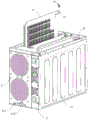
FIG. 3 is a schematic diagram of a server according to an embodiment of the present invention, wherein the cover is not shown;
FIG. 4 is a schematic diagram of a server according to an embodiment of the present invention, wherein the cover and fan module are not shown;
FIG. 5 is a schematic diagram of a fan module of a server according to an embodiment of the invention;
FIG. 6 is a schematic diagram of a control board of a server according to an embodiment of the invention;
FIG. 7 is a schematic diagram of a computing power board of a server according to an embodiment of the invention;
FIG. 8 is a cross-sectional view of a chassis of a server according to an embodiment of the invention;
FIG. 9 is a partial cross-sectional view of a server according to an embodiment of the invention;
FIG. 10 is an enlarged view of portion A circled in FIG. 9;
FIG. 11 is an enlarged view of portion B encircled in FIG. 9;
FIG. 12 is a top view of a body of a server according to an embodiment of the invention;
FIG. 13 is a top view of a server according to an embodiment of the present invention, with the cover not shown;
FIG. 14 is an enlarged view of the portion C encircled in FIG. 13;
fig. 15 is an enlarged view of a portion D circled in fig. 13.
Reference numerals:
100: a server;
1: a chassis; 11: a body; 111: a second card slot; 112: a chute; 12: a cover body;
121: a first card slot; 13: an accommodating space; 14: a separator plate;
2: a power supply module; 21: a power socket; 22: an output end;
3: a control panel; 31: a first socket; 32: a second socket; 33: a signal interface;
4: calculating the strength board; 41: a power taking part; 42: a force calculation board socket;
5: a fan module; 51: a fan bracket; 511: an extension plate; 512: a port through hole;
52: a fan; 53: an adapter plate; 531: a fan receptacle; 532: a golden finger;
6: a partition plate; 7: a fan back plate; 71: a gold finger connector;
72: a fan backplane connector; 73: a socket;
8: a power supply member; 9: a threaded fastener; 10: a cable.
Detailed Description
Embodiments of the present invention will be described in detail below, the embodiments described with reference to the drawings being illustrative, and the embodiments of the present invention will be described in detail below.
A server 100 according to an embodiment of the present invention is described below with reference to fig. 1-15.
As shown in fig. 1 to 15, a server 100 according to an embodiment of the first aspect of the present invention includes a chassis 1, a power module 2, a control board 3, at least one computing board 4, and a fan module 5.
Specifically, the chassis 1 includes a body 11 and a cover 12, the cover 12 is detachably attached to a top of the body 11, and an accommodating space 13 is defined between the cover 12 and the body 11. The cover 12 may be removably attached to the top of the body 11 by snap-fit structures such as snaps and the like and/or threaded fasteners 9. For example, in the example of fig. 1-4, the body 11 and the cover 12 are connected by a snap-fit structure, and a small number of threaded fasteners, such as screws, are used for fastening, so that the cover 12 can be mounted securely and the cover 12 can be detached easily.
The power module 2 and the control board 3 are both disposed in the accommodating space 13. The force calculation plate 4 is provided in the accommodation space 13 so as to be vertically drawable. For example, referring to fig. 1 to 4, the power module 2, the control board 3 and the force calculation board 4 are all located in the accommodating space 13, so that the entire server 100 is compact and the miniaturized design of the server 100 is facilitated. Moreover, because the force calculation plate 4 can be drawn up and down in the accommodating space 13, when the force calculation plate 4 is installed or replaced, the force calculation plate 4 can be directly inserted into or pulled out of the accommodating space 13, so that the installation and replacement of the force calculation plate 4 are facilitated, and the assembly and disassembly efficiency can be improved.
The control panel 3 is electrically connected with the power module 2, and the force calculating panel 4 is electrically connected with both the control panel 3 and the power module 2. When the server 100 is in operation, the power module 2 can supply power to the control board 3 and the force calculation board 4, and meanwhile, the control board 3 can transmit control signals to the force calculation board 4 to ensure the normal operation of the control board 3 and the force calculation board 4.
Referring to fig. 5, the fan module 5 includes a fan bracket 51 and at least one fan 52, the fan 52 is disposed on the fan bracket 51, the fan 52 is electrically connected to both the control board 3 and the power module 2, the fan 52 is located in the accommodating space 13, and the fan module 5 is detachably connected to one end of the body 11 in the length direction through the fan bracket 51. For example, in the example of fig. 5, the fan module 5 may include two fans 52, the two fans 52 are spaced up and down along the length direction of the fan bracket 51, and the two fans 52 may be both located on one side of the fan bracket 51 facing the center of the accommodating space 13.
When the fan module 5 is installed on the body 11, the fan 52 can be effectively ensured to be always located in the accommodating space 13, and compared with the conventional server, the condition that the fan 52 is exposed is effectively avoided, so that the server 100 can smoothly pass through the steel ball impact test, and the safety of the server 100 can be effectively ensured. Furthermore, when the fan 52 needs to be replaced, the fan module 5 can be directly removed from one end of the body 11 in the longitudinal direction, and the maintenance efficiency of the fan module 5 is improved. When the force plate 4 is changed, the cover body 12 can be directly detached, the force plate 4 to be changed is pulled out of the body 11, the fan module 5 does not need to be detached, and the fan module 5 is not easy to damage while the maintainability of the force plate 4 is ensured.
According to the server 100 of the embodiment of the present invention, the fan module 5 is detachably connected to one end of the body 11 in the length direction through the fan bracket 51 by providing the fan 52 at a side of the fan bracket 51 facing the accommodating space 13. Therefore, the condition that the fan 52 is exposed is effectively avoided, the server 100 can smoothly pass through the steel ball impact test, the safety of the server 100 can be effectively ensured, and the maintainability of the fan module 5 and the computing board 4 is improved.
According to some embodiments of the present invention, referring to fig. 5, the fan module 5 further includes an adapter plate 53, the adapter plate 53 is disposed on the fan bracket 51, and the adapter plate 53 is located on a side of the fan bracket 51 adjacent to the center of the accommodating space 13. When the fan module 5 is mounted on the chassis 1, the adapter plate 53 is located in the accommodating space 13, so that the adapter plate 53 can be used normally, and the whole server 100 can be more compact in structure and more regular in appearance. The adapter plate 53 is provided with at least one fan socket 531, the fan socket 531 is electrically connected with the fan 52, and the fan module 5 is electrically connected with both the control board 3 and the power module 2 through the adapter plate 53. For example, in the example of fig. 5, two fans 52 are disposed on the fan bracket 51, and accordingly, two fan sockets 531 may be disposed on the adapter plate 53, the two fan sockets 531 being spaced apart from each other along the length direction of the adapter plate 53, and the two fan sockets 531 may be electrically connected to the two fans 52 through the cables 10, respectively. The adapter plate 53 is electrically connected to both the control board 3 and the power module 2. When the server 100 is in operation, the power module 2 can supply power to the fan 52 through the adapter board 53, so as to ensure the normal operation of the fan 52. Thus, the fan bracket 51 serves as a carrier, and the fan 52 and the adapter plate 53 are integrally mounted, thereby realizing a modular design of the fan 52.
In some alternative embodiments, fan module 5 may be removably attached to body 11 via a snap-fit mechanism, such as a snap fit or the like, or threaded fastener 9, which may effectively improve the ease of installation and removal of fan module 5.
At least one fan 52 may be a high-speed fan, which not only can improve the heat dissipation efficiency of the server 100, but also can reduce the number of fans 52 in the server 100, thereby reducing the cost.
Further, as shown in fig. 1 to 5, the power module 2 is located on one side of the width direction of the fan module 5, which improves the compactness of the server 100. The adapter plate 53 is provided with a golden finger 532 extending towards the other end of the length direction of the body 11, a partition plate 6 is arranged in the accommodating space 13, the partition plate 6 is located between the fan module 5 and the power module 2, a fan back plate 7 is arranged on the surface of one side of the partition plate 6 facing the fan module 5, a golden finger connector 71 is arranged on the fan back plate 7, and the golden finger 532 is matched with the golden finger connector 71 in an inserting manner. When the server 100 is in operation, the power module 2 supplies power to the fan backplane 7, and the fan backplane 7 can supply power to the fan 52 through the golden finger connector 71 and the golden finger 532, so that the fan 52 can be controlled to be turned on and off. Therefore, the mechanical connection between the fan module 5 and the body 11 is realized while the electrical connection is formed by the plug connection of the gold finger connector 71 and the gold finger 532, so that the server 100 has a simple structure and is convenient to assemble. In addition, through setting up division board 6, emergence interference when can effectively avoiding fan module 5 and power module 2 to install, when power module 2 took place the electric leakage phenomenon simultaneously, division board 6 can play insulating effect, prevents that fan module 5 is impaired.
Of course, the present invention is not limited thereto, and the fan module 5 may also be electrically connected to the power module 2 through a connector or a cable 10. It can be understood that the specific connection mode of the fan module 5 and the power module 2 can be specifically set according to actual requirements to better meet practical applications.
Optionally, the power module 2 is detachably connected to one side of the case 1 in the thickness direction, so that the convenience of mounting and dismounting the power module 2 can be effectively improved, and the replacement of the power module 2 is facilitated.
In some alternative embodiments, referring to fig. 5, the fan bracket 51 is provided with an extension plate 511 at a side adjacent to the center of the accommodating space 13, the extension plate 511 is positioned at one side in the width direction of the fan bracket 51, the extension plate 511 extends along the length direction of the fan bracket 51, and the adapter plate 53 is detachably coupled to the extension plate 511. Thus, the extension plate 511 can serve as a mounting carrier for the interposer 53, and the mounting efficiency of the interposer 53 can be improved. Moreover, when the adapter plate 53 fails and needs to be replaced, the adapter plate 53 can be directly replaced without replacing the whole fan module 5, thereby effectively reducing the maintenance cost of the server 100. For example, the adapter plate 53 may be removably attached to the extension plate 511 by threaded fasteners 9, such as screws or the like.
Furthermore, a fan backplane connector 72 is disposed on the fan backplane 7, a first socket 31 is disposed on the control board 3, and the fan backplane connector 72 is vertically plugged into and mated with the first socket 31. As shown in fig. 4 and 6, the fan backplane connector 72 is disposed at an end of the fan backplane 7 adjacent to the control board 3, the first socket 31 is disposed at an end of the control board 3 adjacent to the fan backplane 7, and the fan backplane connector 72 and the first socket 31 cooperate with each other to supply power to the control board 3, thereby ensuring the normal operation of the control board 3 and facilitating the assembly of the fan backplane 7 and the control board 3.
In some alternative embodiments, the fan back plate 7 is provided with a socket 73, and the socket 73 is electrically connected with the power module 2 through the cable 10 or a connector. For example, in the example of fig. 4, the receptacle 73 is provided at the other end in the longitudinal direction of the fan back 7, and the receptacle 73 is connected to the power receptacle 21 of the power module 2 by the cable 10. When the server 100 works, the electric energy of the power module 2 can be transmitted to the fan backplane 7 through the cable 10, a part of the electric energy acquired by the fan backplane 7 is used for supplying power to the fan module 5, and the other part of the electric energy is transmitted to the control board 3 through the fan backplane connector 72, and meanwhile, the control board 3 can transmit the control signal to the fan backplane 7 through the first socket 31 and transmit the control signal to the power module 2 through the cable 10.
According to some embodiments of the present invention, a power supply part 8 is disposed at the top inside the accommodating space 13, one end of the power supply part 8 is connected to the power module 2, at least one power taking part 41 is disposed at the upper part of the computing board 4, one end of the power taking part 41 extends to beyond the outer edge of the computing board 4 and is electrically connected to the power supply part 8, and the power supply part 8 is located outside the outer edge of the computing board 4. For example, in the example of fig. 3, 4 and 7, the top portion inside the accommodating space 13 may be provided with two power supply members 8, one end of each power supply member 8 is connected with the output end 22 of the power module 2, the upper portion of each computing board 4 is provided with two power take-off members 41, and the two power take-off members 41 are detachably connected with the two power supply members 8 respectively through threaded fasteners 9 such as screws or the like. When the power plate 4 needs to be changed, the cover body 12 can be detached firstly, then the screw for fixing the power taking part 41 is detached, and the power supply part 8 is arranged on the outer side of the outer edge of the power plate 4, so that the power supply part 8 can avoid the power plate 4 in the height direction, the power supply part 8 does not need to be detached, and the power plate 4 can be directly pulled out upwards. Therefore, compared with the traditional server, the fan module 5 and the power supply part 8 do not need to be detached when the computing power board 4 is replaced, the fan module 5 can be effectively prevented from being damaged in the detaching process, the maintenance efficiency of the computing power board 4 is improved, and the maintainability of the server 100 is improved. Of course, the computing board 4 may be electrically connected to the power module 2 through a power connector or a power cord. But is not limited thereto.
Further, referring to fig. 3 and 4, the power supply member 8 extends in the thickness direction of the chassis 1. The force calculation plate 4 is provided in plurality. In the description of the present invention, "a plurality" means two or more. The force calculation plates 4 are arranged along the thickness direction of the case 1, and the force calculation plates 4 are electrically connected with the power supply part 8 through the corresponding power taking parts 41. So set up, can follow the direction of height of quick-witted case 1 when changing calculation power board 4 upwards extract calculation power board 4 can, need not to tear down fan module 5, and whole server 100's structure is compacter, make the power of taking 41 of a plurality of calculation power boards 4 simultaneously can be connected with same power supply 8 electricity, can reduce the quantity of power supply 8 in accommodation space 13 effectively, make server 100's structure compacter, and reduce cost.
In some optional embodiments, as shown in fig. 8 to 15, a plurality of first card slots 121 arranged at intervals in the thickness direction of the chassis 1 are provided on the inner surface of the cover 12, a plurality of second card slots 111 arranged at intervals in the thickness direction of the chassis 1 are provided at the lower portion in the main body 11, a plurality of sliding slots 112 arranged at intervals in the thickness direction of the chassis 1 are respectively formed at both sides of the main body 11 in the length direction, a plurality of computation force plates 4 are respectively provided in the corresponding sliding slots 112 and can move up and down along the corresponding sliding slots 112, the top of each computation force plate 4 is fitted in the corresponding first card slot 121, and the bottom of each computation force plate 4 is fitted in the corresponding second card slot 111. For example, a partition plate 14 is disposed at a lower portion in the main body 11, the partition plate 14 is spaced apart from a bottom wall of the main body 11 up and down, the partition plate 14 divides the accommodating space into a first accommodating space and a second accommodating space located below the first accommodating space, and the plurality of second card slots 111 may be disposed on the partition plate 14 and spaced apart from each other in a thickness direction of the chassis 1. Computing power board 4 is located first accommodation space, and control panel 3 is located the second accommodation space, and computing power board 4 is connected with control panel 3 electricity.
When the force calculation plate 4 is installed, the force calculation plate 4 can slide downwards along the sliding grooves 112 on both sides of the length direction of the body 11, and at this time, the sliding grooves 112 play a role in guiding the installation of the force calculation plate 4. After the force calculation plate 4 is installed in place, the second clamping grooves 111 at the lower part of the body 11 can respectively clamp the bottoms of the corresponding force calculation plates 4 so as to limit the lower ends of the force calculation plates 4. After the cover body 12 is covered, the first slots 121 on the inner surface of the cover body 12 can respectively clamp the tops of the corresponding force calculation plates 4, so as to limit the upper ends of the force calculation plates 4. From this for four upper and lower left and right sides position of calculating power board 4 all are blocked, thereby guaranteed the installation stability of calculating power board 4, effectively avoid server 100 during operation to calculate power board 4 and appear rocking, cause the inside abnormal sound of server 100.
Further, the control board 3 is arranged at the bottom in the accommodating space 13, at least one second socket 32 is arranged on the upper surface of the control board 3, an arithmetic board socket 42 is arranged at the bottom of the arithmetic board 4, and the arithmetic board socket 42 is in up-and-down insertion fit with the second socket 32. Referring to fig. 4, 6 and 7, one side of the control board 3 in the width direction is provided with three second sockets 32, and the three second sockets 32 are spaced apart from each other in the length direction of the control board 3. When the force calculation board 4 is installed, the force calculation board socket 42 at the bottom of each force calculation board 4 extends into the second accommodating space to be matched with the corresponding second socket 32, so that the space between the isolation board 14 and the bottom wall of the body 11 can be effectively utilized, the structure of the server 100 is more compact, meanwhile, the control board 3 and the force calculation board 4 can transmit control signals, the force calculation board 4 is convenient to install, and the assembling efficiency is further improved. Of course, the present invention is not limited thereto, and the force calculation board 4 may be electrically connected to the control board 3 through the cable 10.
Referring to fig. 1 to 3, the control board 3 is installed at the bottom of the accommodating space 13, the fan module 5 and the plurality of computation force boards 4 are both located above the control board 3, the fan module 5 and the plurality of computation force boards 4 are respectively located at both sides of the width direction of the control board 3, the plurality of computation force boards 4 are electrically connected to the control board 3 through the computation force board sockets 42 and the second sockets 32, and the fan module 5 is electrically connected to the control board 3 through the fan back plate 7. Thereby, the compactness of the structure of the server 100 can be effectively ensured.
In some alternative embodiments, at least one port through hole 512 is formed on the fan bracket 51, and at least one signal interface 33 is provided on the control board 3, where the signal interface 33 is opposite to the port through hole 512. Referring to fig. 1, 3, 5 and 6, the lower portion of the fan bracket 51 is provided with two port through holes 512, one side of the control board 3 opposite to the second socket 32 is provided with two signal interfaces 33, the shapes of the two port through holes 512 are matched with the shapes of the corresponding signal interfaces 33, and the two signal interfaces 33 respectively correspond to the corresponding port through holes 512 one by one, so that the server 100 can be connected with external parts through the signal interfaces 33.
A data centre (not shown) according to an embodiment of the second aspect of the invention comprises at least one server 100 according to the above-described embodiment of the first aspect of the invention.
According to the data center of the embodiment of the invention, by adopting the server 100, the maintainability of the data center is improved, and the cost of the data center is reduced.
Other constructions and operations of the server 100 according to embodiments of the present invention are known to those of ordinary skill in the art and will not be described in detail herein.
In the description of the present invention, it is to be understood that the terms "center", "length", "width", "thickness", "upper", "lower", "front", "rear", "left", "right", "vertical", "horizontal", "top", "bottom", "inner", "outer", and the like, indicate orientations and positional relationships based on those shown in the drawings, and are used only for convenience in describing the present invention and simplifying the description, but do not indicate or imply that the device or element referred to must have a particular orientation, be constructed and operated in a particular orientation, and thus, should not be construed as limiting the present invention.
In the description of the present invention, it should be noted that, unless otherwise explicitly specified or limited, the terms "mounted," "connected," and "connected" are to be construed broadly, e.g., as meaning either a fixed connection, a removable connection, or an integral connection; can be mechanically or electrically connected; they may be connected directly or indirectly through intervening media, or they may be interconnected between two elements. The specific meanings of the above terms in the present invention can be understood in specific cases to those skilled in the art.
In the description herein, references to the description of the term "one embodiment," "some embodiments," "an illustrative embodiment," "an example," "a specific example," or "some examples" or the like mean that a particular feature, structure, material, or characteristic described in connection with the embodiment or example is included in at least one embodiment or example of the invention. In this specification, the schematic representations of the terms used above do not necessarily refer to the same embodiment or example.
While embodiments of the invention have been shown and described, it will be understood by those of ordinary skill in the art that: various changes, modifications, substitutions and alterations can be made to the embodiments without departing from the principles and spirit of the invention, the scope of which is defined by the claims and their equivalents.
Claims (12)
1. A server, comprising:
the case comprises a body and a cover body, wherein the cover body is detachably connected to the top of the body, and an accommodating space is defined between the cover body and the body;
the power supply module is arranged in the accommodating space;
the control board is arranged in the accommodating space and is electrically connected with the power supply module;
the force calculation board is arranged in the accommodating space in a vertically drawing manner and is electrically connected with the control board and the power module;
the fan module comprises a fan support and at least one fan, the fan is arranged on the fan support, the fan is electrically connected with the control panel and the power supply module, the fan is located in the accommodating space, and the fan module is detachably connected to one end of the body in the length direction through the fan support.
2. The server of claim 1, wherein the fan module further comprises:
the adapter plate is arranged on the fan support and located on one side, close to the containing space center, of the fan support, at least one fan socket is arranged on the adapter plate and electrically connected with the fan, and the fan module is electrically connected with the control panel and the power module through the adapter plate.
3. The server according to claim 2, wherein the power supply module is located on one side in a width direction of the fan module;
the fan module is characterized in that a golden finger extending towards the other end of the body in the length direction is arranged on the adapter plate, a partition plate is arranged in the accommodating space and located between the fan module and the power module, a fan back plate is arranged on one side surface of the partition plate facing the fan module, a golden finger connector is arranged on the fan back plate, and the golden finger is in plug-in fit with the golden finger connector.
4. The server according to claim 3, wherein an extension plate is provided at a side of the fan bracket adjacent to a center of the accommodating space, the extension plate extends in a height direction of the fan bracket, and the adapter plate is detachably attached to the extension plate.
5. The server according to claim 3, wherein a fan backplane connector is disposed on the fan backplane, and a first socket is disposed on the control board, and the fan backplane connector is vertically plugged into and engaged with the first socket.
6. The server according to claim 3, wherein the fan backplane is provided with a socket, and the socket is electrically connected with the power module through a cable or a connector.
7. The server according to any one of claims 1 to 6, wherein a power supply member is provided at a top portion in the accommodating space, and one end of the power supply member is connected to the power supply module;
the upper portion of calculation power board is equipped with at least one electricity piece of getting, the one end of getting extend to and surpass calculation power board's outer fringe and with the power supply unit electricity is connected, just the power supply unit is located calculation power board the outside at outer fringe.
8. The server according to claim 7, wherein the control board is provided at a bottom portion in the accommodating space, and at least one second socket is provided on an upper surface of the control board;
and the bottom of the force calculation board is provided with a force calculation board socket, and the force calculation board socket is in up-and-down insertion fit with the second socket.
9. The server according to claim 7, wherein the power supply member extends in a thickness direction of the chassis;
the power calculation plates are arranged along the thickness direction of the case and are electrically connected with the power supply part through the corresponding power taking part.
10. The server according to claim 9, wherein a plurality of first engaging grooves are formed on an inner surface of the cover at intervals in a thickness direction of the chassis, a plurality of second engaging grooves are formed on a lower portion of the body at intervals in the thickness direction of the chassis, a plurality of sliding grooves are formed on both sides of the body in a length direction of the body at intervals in the thickness direction of the chassis, the computing boards are respectively disposed in the corresponding sliding grooves and are movable up and down along the corresponding sliding grooves, a top of each computing board is engaged with the corresponding first engaging groove, and a bottom of each computing board is engaged with the corresponding second engaging groove.
11. The server according to any one of claims 1 to 6, wherein the fan bracket is formed with at least one port through-hole;
the control panel is provided with at least one signal interface, and the signal interface is opposite to the port through hole.
12. A data center, characterized in that it comprises at least one server according to any one of claims 1-11.
Priority Applications (1)
| Application Number | Priority Date | Filing Date | Title |
|---|---|---|---|
| CN202011306193.5A CN112394781A (en) | 2020-11-19 | 2020-11-19 | Server and data center with same |
Applications Claiming Priority (1)
| Application Number | Priority Date | Filing Date | Title |
|---|---|---|---|
| CN202011306193.5A CN112394781A (en) | 2020-11-19 | 2020-11-19 | Server and data center with same |
Publications (1)
| Publication Number | Publication Date |
|---|---|
| CN112394781A true CN112394781A (en) | 2021-02-23 |
Family
ID=74607162
Family Applications (1)
| Application Number | Title | Priority Date | Filing Date |
|---|---|---|---|
| CN202011306193.5A Pending CN112394781A (en) | 2020-11-19 | 2020-11-19 | Server and data center with same |
Country Status (1)
| Country | Link |
|---|---|
| CN (1) | CN112394781A (en) |
Cited By (3)
| Publication number | Priority date | Publication date | Assignee | Title |
|---|---|---|---|---|
| USD973654S1 (en) * | 2018-10-30 | 2022-12-27 | Bitmain Technologies Inc. | Supercomputing device |
| USD979561S1 (en) * | 2018-10-30 | 2023-02-28 | Bitmain Technologies Inc. | Supercomputing device |
| WO2023186147A1 (en) * | 2022-04-02 | 2023-10-05 | 北京嘉楠捷思信息技术有限公司 | Heat dissipation apparatus and computing device |
Citations (6)
| Publication number | Priority date | Publication date | Assignee | Title |
|---|---|---|---|---|
| CN101639712A (en) * | 2008-07-31 | 2010-02-03 | 英业达股份有限公司 | Server |
| US20110194245A1 (en) * | 2010-02-06 | 2011-08-11 | Inventec Corporation | Server |
| CN202025265U (en) * | 2010-11-19 | 2011-11-02 | 曙光信息产业(北京)有限公司 | Server case |
| CN103677183A (en) * | 2013-12-04 | 2014-03-26 | 曙光信息产业(北京)有限公司 | Fan module used for server and server |
| TWI571726B (en) * | 2015-12-11 | 2017-02-21 | 英業達股份有限公司 | Electronic device |
| CN110989787A (en) * | 2019-12-02 | 2020-04-10 | 北京比特大陆科技有限公司 | Liquid cooling server |
-
2020
- 2020-11-19 CN CN202011306193.5A patent/CN112394781A/en active Pending
Patent Citations (6)
| Publication number | Priority date | Publication date | Assignee | Title |
|---|---|---|---|---|
| CN101639712A (en) * | 2008-07-31 | 2010-02-03 | 英业达股份有限公司 | Server |
| US20110194245A1 (en) * | 2010-02-06 | 2011-08-11 | Inventec Corporation | Server |
| CN202025265U (en) * | 2010-11-19 | 2011-11-02 | 曙光信息产业(北京)有限公司 | Server case |
| CN103677183A (en) * | 2013-12-04 | 2014-03-26 | 曙光信息产业(北京)有限公司 | Fan module used for server and server |
| TWI571726B (en) * | 2015-12-11 | 2017-02-21 | 英業達股份有限公司 | Electronic device |
| CN110989787A (en) * | 2019-12-02 | 2020-04-10 | 北京比特大陆科技有限公司 | Liquid cooling server |
Cited By (3)
| Publication number | Priority date | Publication date | Assignee | Title |
|---|---|---|---|---|
| USD973654S1 (en) * | 2018-10-30 | 2022-12-27 | Bitmain Technologies Inc. | Supercomputing device |
| USD979561S1 (en) * | 2018-10-30 | 2023-02-28 | Bitmain Technologies Inc. | Supercomputing device |
| WO2023186147A1 (en) * | 2022-04-02 | 2023-10-05 | 北京嘉楠捷思信息技术有限公司 | Heat dissipation apparatus and computing device |
Similar Documents
| Publication | Publication Date | Title |
|---|---|---|
| CN112394781A (en) | Server and data center with same | |
| CN107437669B (en) | Cable backplane system with individually removable cable connector assemblies | |
| CN112394780A (en) | Server and data center with same | |
| US7692928B2 (en) | Interface assembly | |
| US6018456A (en) | Enclosure for removable computer peripheral equipment | |
| US20060107678A1 (en) | Cooling arrangement | |
| CN210839636U (en) | Switch | |
| CN112748774A (en) | Edge server chassis | |
| CN112394782A (en) | Server and data center with same | |
| CN215729603U (en) | Server chassis | |
| CN215729605U (en) | Server chassis | |
| CN215729604U (en) | Server chassis | |
| US20100214755A1 (en) | Backplane for an electronic mounting rack | |
| EP2867744A1 (en) | Power supply and circuit module for data processing system | |
| CN213780844U (en) | Server and data center with same | |
| CN214544542U (en) | Modularized display device | |
| CN209842460U (en) | Extension type control device and host machine of extension type control device | |
| CN211744552U (en) | Video processing apparatus | |
| CN211859104U (en) | Switching subassembly and specification type subassembly thereof | |
| US6816390B1 (en) | Apparatus for blind swap cassette guidance | |
| US8128424B2 (en) | Electrical receptacle assembly | |
| CN218003628U (en) | Cabinet for radio frequency front-end chip ATE (automatic test equipment) volume production test | |
| CN219891590U (en) | Industrial control computer | |
| CN220254814U (en) | Server device | |
| CN220776314U (en) | Array connection structure and electronic equipment |
Legal Events
| Date | Code | Title | Description |
|---|---|---|---|
| PB01 | Publication | ||
| PB01 | Publication | ||
| SE01 | Entry into force of request for substantive examination | ||
| SE01 | Entry into force of request for substantive examination |