Disclosure of Invention
The invention provides a leakage-preventing one-way valve structure, and aims to solve the problems that the existing valve core is complex in structure and poor in sealing effect, liquid in the valve easily flows reversely, the use effect is influenced, the valve core cannot be adjusted according to the requirements of users, and the use limitation is large.
The invention is realized in such a way, the one-way valve structure for avoiding leakage comprises a valve body, wherein a mounting sleeve is fixedly arranged at the middle position of one end in the valve body, a movable block is movably arranged at one end in the mounting sleeve, a supporting spring is fixedly arranged at one side of the movable block, one end of the supporting spring is fixedly connected with one side in the mounting sleeve, a movable rod is fixedly arranged at the middle position of one side of the movable block, one end of the movable rod is movably inserted in the outer side of the mounting sleeve, a fixed check ring is fixedly arranged at one side in the valve body, a discharge hole is formed in the surface of the fixed check ring, the movable rod is movably inserted in the discharge hole, a movable check ring is movably arranged at one side of the fixed check ring, one side of the movable check ring is fixedly connected with one side of the movable rod, a sealing block is fixedly, the utility model discloses a valve body, including valve body, sealed piece, discharge gate, valve body, movable sleeve, return ring, sealed piece with the discharge gate is connected, the inside one side movable mounting of valve body has rotatory swivel nut, the inside activity interlude of rotatory swivel nut one end has telescopic screw, telescopic screw's one end activity interlude is in the outside of rotatory swivel nut, and this end movable sleeve is equipped with the movable sleeve, the one end of movable sleeve with one side fixed connection of removal retaining ring, the inside one end fixed mounting of movable sleeve has reset spring, its one end with telescopic screw's one end.
Preferably, the diameter of the fixed retainer ring is larger than that of the movable retainer ring, and the shape of the sealing block is equal to that of the discharge hole.
Preferably, one end of the rotary threaded sleeve is movably inserted in the outer side of the valve body in a penetrating mode, a rotary handle is fixedly installed at the end of the rotary threaded sleeve, and anti-skid threads are arranged on the surface of the rotary handle.
Preferably, the both sides of the inside of movable sleeve are all fixedly mounted with a limiting groove, the limiting groove is located the both sides of telescopic screw one end are the symmetric distribution, the inside movable mounting of limiting groove has the stopper, two the stopper respectively with the both sides fixed connection of telescopic screw one end.
Preferably, the two ends of the valve body are respectively provided with a discharge hole and a feed inlet, and the feed inlet is positioned on one side of the fixed check ring.
Preferably, the sliding grooves are formed in two sides of the inner portion of the mounting sleeve, the sliding blocks are fixedly mounted on two sides of the surface of the movable block, and the sliding blocks are movably connected with the sliding grooves.
Preferably, the both sides on installation cover surface all fixed mounting have the installation pole, the one end of installation pole with one side fixed connection of valve body inner wall.
Compared with the prior art, the invention has the beneficial effects that: the invention relates to a leakage-preventing one-way valve structure, which comprises the following components:
1. through the arrangement of the mounting sleeve, the integral device has good sealing effect, when a user uses the integral device, the valve body is fixed at the use position, the discharge port and the feed port are respectively connected with other equipment through flanges, liquid enters the interior of the valve body through the feed port, when the liquid is contacted with the fixed check ring, pressure is generated on the movable check ring, the movable check ring moves, the movable check ring drives the movable rod to move, the movable rod drives the movable block to move in the interior of the mounting sleeve, the supporting spring is compressed, the liquid is discharged from the discharge port through the discharge port, thereby facilitating the flow of the liquid, when the flow is stopped, the movable block recovers the original position under the action of the supporting spring, the movable block drives the movable check ring to move through the movable rod, the sealing block on one side of the movable check ring is attached to the discharge port, the discharge port is convenient to be blocked, liquid backflow is avoided;
2. when removing the retaining ring and removing, promote the movable sleeve and remove along telescopic screw's surface, the movable sleeve compresses reset spring, when removing the retaining ring and reseing, under reset spring's effect, the laminating of removing retaining ring and retaining ring has been strengthened, the leakproofness has been strengthened, when the valve body is according to user's demand reverse flow, the user drives rotatory swivel nut through rotatory handle and rotates, rotatory swivel nut drives telescopic screw and contracts, telescopic screw drives the movable sleeve through stopper and spacing groove and removes, the movable sleeve drives the removal retaining ring and removes, make liquid can flow back, be convenient for adjust the valve body.
Detailed Description
In order to make the objects, technical solutions and advantages of the present invention more apparent, the present invention is described in further detail below with reference to the accompanying drawings and embodiments. It should be understood that the specific embodiments described herein are merely illustrative of the invention and are not intended to limit the invention.
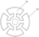
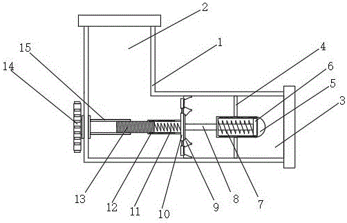
Referring to fig. 1-3, the present invention provides a technical solution of a check valve structure for preventing leakage: comprises a valve body 1, a mounting sleeve 5 is fixedly arranged at the middle position of one end inside the valve body 1, a movable block 6 is movably arranged at one end inside the mounting sleeve 5, a supporting spring 7 is fixedly arranged at one side of the movable block 6, one end of the supporting spring is fixedly connected with one side inside the mounting sleeve 5, a movable rod 8 is fixedly arranged at the middle position of one side of the movable block 6, one end of the movable rod is movably inserted outside the mounting sleeve 5, a fixed check ring 9 is fixedly arranged at one side inside the valve body 1, a discharge hole 17 is arranged on the surface of the fixed check ring 9, a movable rod 8 is movably inserted inside the discharge hole 17, a movable check ring 10 is movably arranged at one side of the fixed check ring 9, one side of the movable check ring 10 is fixedly connected with one side of the movable rod 8, a sealing block 16 is fixedly arranged at one side of the movable check ring 10, the sealing block 16 is, a telescopic screw 13 is movably inserted in one end of the rotary threaded sleeve 15, one end of the telescopic screw 13 is movably inserted in the outer side of the rotary threaded sleeve 15, a movable sleeve 12 is movably sleeved at the end, one end of the movable sleeve 12 is fixedly connected with one side of the movable check ring 10, a return spring 11 is fixedly installed at one end of the inner part of the movable sleeve 12, and one end of the return spring is fixedly connected with one end of the telescopic screw 13.
In this embodiment, when the liquid will contact the fixed retainer 9, pressure is generated on the movable retainer 10, the movable retainer 10 moves, the movable retainer 10 drives the movable rod 8 to move, the movable rod 8 drives the movable block 6 to move inside the mounting sleeve 5, and the support spring 7 is compressed, so that the liquid is discharged through the discharge port 17, thereby facilitating the flow of the liquid, when the flow stops, the movable block 6 returns to the original position under the action of the support spring 7, the movable block 6 drives the movable retainer 10 to move through the movable rod 8, so that the sealing block 16 on one side of the movable retainer 10 is attached to the discharge port 17, thereby facilitating the blockage of the discharge port 17, enhancing the sealing effect, avoiding the backflow of the liquid, when the movable retainer 10 moves, the movable sleeve 12 is pushed to move along the surface of the telescopic screw 13, and the movable sleeve 12 compresses the return spring 11, when removing retaining ring 10 and reseing, under reset spring 11's effect, the laminating of removing retaining ring 10 and retaining ring 9 has been strengthened, the leakproofness has been strengthened, when valve body 1 is according to user's demand reverse flow, the user drives rotatory swivel nut 15 through rotatory handle 14 and rotates, rotatory swivel nut 15 drives telescopic screw 13 and contracts, telescopic screw 13 drives movable sleeve 12 through stopper and spacing groove and removes, movable sleeve 12 drives and removes retaining ring 10 and removes, make liquid can flow back, be convenient for adjust valve body 1.
Further, the diameter of the fixed retainer 9 is larger than that of the movable retainer 10, and the shape of the sealing block 16 is equal to that of the discharge hole 17.
In the embodiment, the sealing effect of the discharge hole 17 is enhanced by the arrangement of the sealing block 16, and meanwhile, the diameter of the fixed check ring 9 is larger than that of the movable check ring 10, so that better liquid flow is facilitated.
Furthermore, one end of the rotary threaded sleeve 15 is movably inserted outside the valve body 1, a rotary handle 14 is fixedly installed at the end, and anti-skid threads are arranged on the surface of the rotary handle 14.
In this embodiment, the user can rotate the rotary screw sleeve 15 by the rotary handle 14, so as to move the movable check ring 10.
Further, the both sides of the inside of movable sleeve 12 are all fixedly mounted with a spacing groove, the both sides that the spacing groove is located telescopic screw 13 one end are the symmetric distribution, and the inside movable mounting of spacing groove has the stopper, two stoppers respectively with telescopic screw 13 one end's both sides fixed connection.
In the present embodiment, the movable connection between the movable sleeve 12 and the telescopic screw 13 is strengthened
Further, both ends of the valve body 1 are respectively provided with a discharge opening 2 and a feed inlet 3, and the feed inlet 3 is positioned on one side of the fixed check ring 9.
In this embodiment, when the user uses the valve body 1, the discharge opening 2 and the feed opening 3 are connected to other devices via flanges, respectively, and liquid enters the valve body 1 through the feed opening 3.
Further, the spout has all been seted up to the inside both sides of installation cover 5, and the equal fixed mounting in both sides on 6 surfaces of movable block has the slider, slider and spout swing joint.
In this embodiment, the swing joint of the mounting sleeve 5 and the movable block 6 is strengthened, so that the movable retainer ring 10 is kept in an original state under the action of the mounting sleeve 5, rotation is avoided, the telescopic screw 13 is limited, and the phenomenon that the rotary screw sleeve 15 drives the telescopic screw 13 to rotate to influence the contraction of the telescopic screw 13 is avoided.
Furthermore, the two sides of the surface of the mounting sleeve 5 are fixedly provided with mounting rods 4, and one end of each mounting rod 4 is fixedly connected with one side of the inner wall of the valve body 1.
In this embodiment, the user can fix the mounting sleeve 5 by the mounting rod 4.
The working principle and the using process of the invention are as follows: when a user uses the valve body 1, the valve body 1 is fixed at the use position, the discharge port 2 and the feed port 3 are respectively connected with other equipment through flanges, after the valve is installed, liquid enters the interior of the valve body 1 through the feed port 3, when the liquid is in contact with the fixed check ring 9, pressure is generated on the movable check ring 10, the movable check ring 10 moves, the movable check ring 10 drives the movable rod 8 to move, the movable rod 8 drives the movable block 6 to move in the interior of the installation sleeve 5, the supporting spring 7 is compressed, the liquid is discharged from the discharge port 17 through the discharge port 17, so that the liquid can conveniently flow, when the flow is stopped, the movable block 6 is restored to the original position under the action of the supporting spring 7, the movable block 6 drives the movable check ring 10 to move through the movable rod 8, the sealing block 16 on one side of the movable check ring 10 is attached to the discharge port 17, and the, strengthened sealed effect, avoid the liquid backward flow, when removing retaining ring 10 and removing, promote movable sleeve 12 and remove along telescopic screw 13's surface, movable sleeve 12 compresses reset spring 11, when removing retaining ring 10 and reseing, under reset spring 11's effect, the laminating of removing retaining ring 10 and retaining ring 9 has been strengthened, the leakproofness has been strengthened, when valve body 1 is according to user's demand reverse flow, the user drives rotatory swivel nut 15 through rotatory handle 14 and rotates, rotatory swivel nut 15 drives telescopic screw 13 and contracts, telescopic screw 13 drives movable sleeve 12 through stopper and spacing groove and removes, movable sleeve 12 drives removal retaining ring 10 and removes, make liquid can flow back, be convenient for adjust valve body 1.
The above description is only for the purpose of illustrating the preferred embodiments of the present invention and is not to be construed as limiting the invention, and any modifications, equivalents and improvements made within the spirit and principle of the present invention are intended to be included within the scope of the present invention.