CN112360874A - Bearing and sealing device - Google Patents
Bearing and sealing device Download PDFInfo
- Publication number
- CN112360874A CN112360874A CN202011238020.4A CN202011238020A CN112360874A CN 112360874 A CN112360874 A CN 112360874A CN 202011238020 A CN202011238020 A CN 202011238020A CN 112360874 A CN112360874 A CN 112360874A
- Authority
- CN
- China
- Prior art keywords
- bearing
- hole
- sealing
- oil
- sealing device
- Prior art date
- Legal status (The legal status is an assumption and is not a legal conclusion. Google has not performed a legal analysis and makes no representation as to the accuracy of the status listed.)
- Pending
Links
- 238000007789 sealing Methods 0.000 title claims abstract description 83
- 238000003860 storage Methods 0.000 claims abstract description 44
- 239000000945 filler Substances 0.000 claims description 16
- 239000000463 material Substances 0.000 claims description 7
- 238000009434 installation Methods 0.000 claims description 2
- 239000004519 grease Substances 0.000 abstract description 43
- 230000001050 lubricating effect Effects 0.000 abstract description 40
- 230000000694 effects Effects 0.000 abstract description 7
- 238000000034 method Methods 0.000 abstract description 7
- 230000002045 lasting effect Effects 0.000 abstract description 2
- 239000003921 oil Substances 0.000 description 109
- 239000000314 lubricant Substances 0.000 description 22
- 238000005096 rolling process Methods 0.000 description 18
- 238000002347 injection Methods 0.000 description 10
- 239000007924 injection Substances 0.000 description 10
- 230000009471 action Effects 0.000 description 8
- 238000005461 lubrication Methods 0.000 description 6
- 238000010586 diagram Methods 0.000 description 5
- 230000008569 process Effects 0.000 description 5
- 230000002035 prolonged effect Effects 0.000 description 4
- 238000009826 distribution Methods 0.000 description 3
- 238000001125 extrusion Methods 0.000 description 3
- 230000002349 favourable effect Effects 0.000 description 2
- 239000010687 lubricating oil Substances 0.000 description 2
- 239000000243 solution Substances 0.000 description 2
- 239000002562 thickening agent Substances 0.000 description 2
- 230000005540 biological transmission Effects 0.000 description 1
- 230000007774 longterm Effects 0.000 description 1
- 230000009347 mechanical transmission Effects 0.000 description 1
- 238000012986 modification Methods 0.000 description 1
- 230000004048 modification Effects 0.000 description 1
- 239000004033 plastic Substances 0.000 description 1
- 238000004064 recycling Methods 0.000 description 1
- 239000007787 solid Substances 0.000 description 1
Images


Classifications
-
- F—MECHANICAL ENGINEERING; LIGHTING; HEATING; WEAPONS; BLASTING
- F16—ENGINEERING ELEMENTS AND UNITS; GENERAL MEASURES FOR PRODUCING AND MAINTAINING EFFECTIVE FUNCTIONING OF MACHINES OR INSTALLATIONS; THERMAL INSULATION IN GENERAL
- F16C—SHAFTS; FLEXIBLE SHAFTS; ELEMENTS OR CRANKSHAFT MECHANISMS; ROTARY BODIES OTHER THAN GEARING ELEMENTS; BEARINGS
- F16C19/00—Bearings with rolling contact, for exclusively rotary movement
- F16C19/02—Bearings with rolling contact, for exclusively rotary movement with bearing balls essentially of the same size in one or more circular rows
- F16C19/14—Bearings with rolling contact, for exclusively rotary movement with bearing balls essentially of the same size in one or more circular rows for both radial and axial load
- F16C19/16—Bearings with rolling contact, for exclusively rotary movement with bearing balls essentially of the same size in one or more circular rows for both radial and axial load with a single row of balls
-
- F—MECHANICAL ENGINEERING; LIGHTING; HEATING; WEAPONS; BLASTING
- F16—ENGINEERING ELEMENTS AND UNITS; GENERAL MEASURES FOR PRODUCING AND MAINTAINING EFFECTIVE FUNCTIONING OF MACHINES OR INSTALLATIONS; THERMAL INSULATION IN GENERAL
- F16C—SHAFTS; FLEXIBLE SHAFTS; ELEMENTS OR CRANKSHAFT MECHANISMS; ROTARY BODIES OTHER THAN GEARING ELEMENTS; BEARINGS
- F16C33/00—Parts of bearings; Special methods for making bearings or parts thereof
- F16C33/30—Parts of ball or roller bearings
- F16C33/66—Special parts or details in view of lubrication
- F16C33/6637—Special parts or details in view of lubrication with liquid lubricant
- F16C33/6659—Details of supply of the liquid to the bearing, e.g. passages or nozzles
-
- F—MECHANICAL ENGINEERING; LIGHTING; HEATING; WEAPONS; BLASTING
- F16—ENGINEERING ELEMENTS AND UNITS; GENERAL MEASURES FOR PRODUCING AND MAINTAINING EFFECTIVE FUNCTIONING OF MACHINES OR INSTALLATIONS; THERMAL INSULATION IN GENERAL
- F16C—SHAFTS; FLEXIBLE SHAFTS; ELEMENTS OR CRANKSHAFT MECHANISMS; ROTARY BODIES OTHER THAN GEARING ELEMENTS; BEARINGS
- F16C33/00—Parts of bearings; Special methods for making bearings or parts thereof
- F16C33/72—Sealings
- F16C33/76—Sealings of ball or roller bearings
- F16C33/78—Sealings of ball or roller bearings with a diaphragm, disc, or ring, with or without resilient members
- F16C33/7803—Sealings of ball or roller bearings with a diaphragm, disc, or ring, with or without resilient members suited for particular types of rolling bearings
- F16C33/7806—Sealings of ball or roller bearings with a diaphragm, disc, or ring, with or without resilient members suited for particular types of rolling bearings for spherical roller bearings
-
- F—MECHANICAL ENGINEERING; LIGHTING; HEATING; WEAPONS; BLASTING
- F16—ENGINEERING ELEMENTS AND UNITS; GENERAL MEASURES FOR PRODUCING AND MAINTAINING EFFECTIVE FUNCTIONING OF MACHINES OR INSTALLATIONS; THERMAL INSULATION IN GENERAL
- F16C—SHAFTS; FLEXIBLE SHAFTS; ELEMENTS OR CRANKSHAFT MECHANISMS; ROTARY BODIES OTHER THAN GEARING ELEMENTS; BEARINGS
- F16C33/00—Parts of bearings; Special methods for making bearings or parts thereof
- F16C33/72—Sealings
- F16C33/76—Sealings of ball or roller bearings
- F16C33/78—Sealings of ball or roller bearings with a diaphragm, disc, or ring, with or without resilient members
- F16C33/7816—Details of the sealing or parts thereof, e.g. geometry, material
- F16C33/782—Details of the sealing or parts thereof, e.g. geometry, material of the sealing region
Abstract
The embodiment of the invention provides a bearing and a sealing device, wherein the sealing device comprises a sealing part which is of an annular structure as a whole; the elastic part is fixedly connected with the sealing part, the elastic part and the sealing part are arranged at intervals along the axial direction of the sealing device, an oil storage cavity is formed between the elastic part and the sealing part, the elastic part is provided with a through hole, the opening of the through hole is positioned at the radial outer side part or the radial inner side part of the end face of the elastic part, after the sealing device is installed on a bearing ring of the bearing, the distance between the elastic part and the inner cavity of the bearing is smaller than that between the sealing part and the inner cavity, and the through hole is suitable for communicating the oil storage cavity and the inner cavity. At bearing operation in-process, utilize elasticity portion to produce under the pressure effect and warp for the lubricating grease who stores in the oil storage intracavity passes through the through-hole and flows, constantly provides lubricating grease for the bearing, guarantees the lasting operation of bearing, not only improves lubricated effect, prolongs bearing life, simple structure moreover, easily processing, the cost is lower.
Description
Technical Field
The embodiment of the invention relates to the technical field of mechanical sealing, in particular to a bearing and a sealing device.
Background
The bearing is a component for fixing and reducing the load friction coefficient in the mechanical transmission process, and the main function of the bearing is to support the mechanical rotating body so as to reduce the mechanical load friction coefficient of the equipment in the transmission process. As important influencing factors of bearing life, the lubrication mode of the bearing and the amount of lubricant are always key design factors for determining the performance of the bearing.
However, the bearing has a problem of poor lubrication after long-term operation, resulting in a limited life of the bearing.
Therefore, how to prolong the service life of the bearing is a technical problem to be solved urgently by the technical personnel in the field.
Disclosure of Invention
The technical problem solved by the embodiment of the invention is to prolong the service life of the bearing.
To solve the above problem, an embodiment of the present invention provides a sealing device, including:
the sealing part is of an annular structure as a whole;
elastic part, with sealing portion fixed connection, elastic part with the sealing portion is followed sealing device's axial interval arrangement and be formed with the oil storage chamber between the two, the through-hole that the opening is located the radial outside portion or the radial inside portion of its terminal surface is seted up to elastic part, works as behind the race ring of bearing is installed to sealing device, follows on the axial direction of bearing, elastic part with the distance of the inner chamber of bearing is less than sealing portion with the distance of inner chamber, the through-hole is suitable for the intercommunication the oil storage chamber with the bearing inner chamber.
Optionally, the through-hole includes an oil filler point and an oil outlet, an opening of the oil filler point is disposed at a radially outer side portion of the end surface of the elastic portion, and an opening of the oil outlet is disposed at a radially inner side portion of the end surface of the elastic portion.
Optionally, the through-hole includes a tapered hole, the oil filler point is located the aperture size of elasticity portion surface and is greater than the oil filler point is located the aperture size of elasticity portion internal surface, the oil outlet is located the aperture size of elasticity portion surface and is less than the oil outlet is located the aperture size of elasticity portion internal surface.
Optionally, in a cross section of the elastic portion, a bore size of the oil outlet is smaller than a bore size of the oil injection hole.
Optionally, the number of the oil injection holes is equal to the number of the oil outlet holes, and the oil injection holes and the oil outlet holes are arranged at intervals in the circumferential direction of the elastic portion.
Optionally, the number of the through holes is at least 4, and the through holes are uniformly arranged along the circumferential direction of the sealing device.
Optionally, the material of the elastic part is a rubber material.
In order to solve the above problem, an embodiment of the present invention further provides a bearing, including a bearing inner ring, a bearing outer ring, and the sealing devices, where the sealing devices are respectively disposed between the bearing outer ring and the bearing inner ring, and a distance between the elastic portion and an inner cavity of the bearing is smaller than a distance between the sealing portion and the inner cavity.
Compared with the prior art, the technical scheme of the embodiment of the invention has the following advantages:
the sealing device provided by the embodiment of the invention comprises: wholly be annular structure's sealing and elastic component, elastic component with the sealing is followed sealing device's axial interval arrangement and between the two are formed with the oil storage chamber, the through-hole that the opening is located the radial outside portion or the radial inside portion of its terminal surface is seted up to elastic component, before installing sealing device to the race, can pour into a certain amount of lubricating grease into in to the oil storage chamber through the through-hole, works as after sealing device installs the bearing, follow on the axial direction of bearing, elastic component with the distance of the inner chamber of bearing is less than sealing with the distance of inner chamber, the through-hole intercommunication the oil storage chamber with the inner chamber of bearing. I.e. the resilient portion is close to the inner cavity of the bearing and the sealing portion is remote from the inner cavity of the bearing as part of the axial end of the bearing. When the bearing starts to operate, the pressure of the inner cavity of the bearing rises, because the elastic part is close to the inner cavity of the bearing, the elastic part generates extrusion deformation under the action of pressure, namely, the inner space of the oil storage cavity is compressed, lubricating grease in the oil storage cavity is extruded and is extruded to the radial inner side part and the radial outer side part of the elastic part, the lubricating grease can be extruded through the through holes distributed on the radial inner side part or the radial outer side part and enters the inner cavity of the bearing, the lubricating grease is continuously supplied for the bearing when the bearing operates at a high speed, the bearing is ensured to still have a stable lubricating oil film after operating for a long time, the lubricating effect is improved, the conditions of temperature rise, noise and the like are improved, and the service.
It can be seen that, in the sealing device provided by the embodiment of the invention, during the operation of the bearing, the elastic part is deformed under the action of pressure, so that the lubricating grease stored in the oil storage cavity flows out through the through hole, the lubricating grease is continuously provided for the bearing, the bearing is ensured to operate durably, the lubricating effect is improved, the service life of the bearing is prolonged, and the sealing device is simple in structure, easy to process and low in cost.
In the alternative, the through-hole includes oil filler point and oil outlet, the opening of oil filler point set up in the radial outside portion of the terminal surface of elasticity portion, the opening of oil outlet set up in the radial inside portion of the terminal surface of elasticity portion. The oil filler point is used for injecting grease into the oil storage cavity, the oil outlet is used for conveying the lubricating grease in the oil storage cavity to the inside of the bearing. When the bearing inner ring rotates, the extruded lubricating grease can enter the friction position between the inner ring raceway and the rolling body to play a role in lubrication along with the gradual increase of the extrusion amount. Along with the continuous operation of the bearing and the action of centrifugal force, the supplied lubricant gradually moves from the joint of the inner ring raceway and the rolling body to the joint of the outer ring raceway and the rolling body, and is finally accumulated at the joint of the outer ring shoulder and the sealing ring. At the moment, because of the gradient distribution of the pressure inside the bearing, the lubricant enters the oil storage cavity from the oil injection hole again under the action of higher pressure outside the bearing, and gradually moves towards the oil outlet hole in the cavity, so that a lubricant circulating system is formed between the inside of the bearing and the sealing device, namely, the lubricant forms an infinite circulating system from the oil storage cavity, the oil outlet hole, the inner ring roller path, the rolling body, the outer ring roller path, the oil injection hole and the oil storage cavity, and the lubricant circulating system is created in the limited space inside the bearing, so that more lubricant participates in the lubricating action of the friction part, the utilization rate of the lubricant is improved, the bearing has continuous self-lubricating performance, and the service life and the running state of the bearing are prolonged. Moreover, as the bearing operates, the lubricating grease is sheared, the thickening agent in the lubricating grease is smashed, the viscosity of the lubricating grease is reduced, the fluidity is enhanced, and the circulation effect is further provided. Furthermore, an external device or special processing of the inner ring and the outer ring is not needed to connect a lubricant circulating system, the structure is compact, and the cost is saved.
In the alternative, the through-hole includes the bell mouth, the oil filler point be located the aperture size of elasticity portion surface be greater than the oil filler point be located the aperture size of elasticity portion internal surface, the aperture size that is located the elasticity portion surface of oil outlet is less than the aperture size that is located the elasticity portion internal surface of oil outlet. Through designing into the oil filler point the bell mouth, be more convenient for pour into the oil storage chamber with lubricating grease into, through designing into the bell mouth with the oil outlet, be favorable to the lubricating grease in the oil storage intracavity to flow along the oil outlet.
Drawings
In order to more clearly illustrate the embodiments of the present application or the technical solutions in the prior art, the drawings needed to be used in the description of the embodiments or the prior art will be briefly introduced below, it is obvious that the drawings in the following description are only embodiments of the present application, and for those skilled in the art, other drawings can be obtained according to the provided drawings without creative efforts.
FIG. 1 is a schematic structural diagram of a sealing device provided in an embodiment of the present invention;
FIG. 2 is a partial schematic view of a sealing device provided in accordance with an embodiment of the present invention;
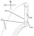
FIG. 3 is a schematic diagram of the pressures experienced by the seal assembly during operation according to an embodiment of the present invention;
FIG. 4 is a schematic view of the sealing device according to the present invention;
FIG. 5 is a simplified schematic illustration of a longitudinal section of a sealing device provided in accordance with an embodiment of the present invention;
FIG. 6 is a partial schematic view of a bearing provided by an embodiment of the present invention;
fig. 7 is a schematic diagram of a grease circulation path of a bearing provided by an embodiment of the invention.
Wherein: 10-a sealing part; 100-an oil storage chamber; 20-an elastic portion; 30-a through hole; 31-oil holes; 32-oil outlet holes; 40-a bearing outer ring; 50-bearing inner race; 60-rolling elements.
Detailed Description
As known from the background art, the service life of the current bearings is not good.
In order to prolong the service life of the bearing, the embodiment of the invention provides the bearing and the sealing device, in the running process of the bearing, the elastic part is deformed under the action of pressure, so that the lubricating grease stored in the oil storage cavity flows out through the through holes, the lubricating grease is continuously provided for the bearing, the bearing is ensured to run for a long time, the lubricating effect is improved, the service life of the bearing is prolonged, the structure is simple, the processing is easy, and the cost is lower.
The technical solutions in the embodiments of the present invention will be clearly and completely described below with reference to the drawings in the embodiments of the present invention, and it is obvious that the described embodiments are only a part of the embodiments of the present invention, and not all of the embodiments. All other embodiments, which can be derived by a person skilled in the art from the embodiments given herein without making any creative effort, shall fall within the protection scope of the present invention.
It should be noted that the indication of the direction or the positional relationship referred to in the present specification is based on the direction or the positional relationship shown in the drawings, and is only for convenience of description and simplification of description, and it is not intended to indicate or imply that the indicated device must have a specific direction, be configured in a specific direction, and thus, should not be construed as limiting the present invention.
Referring to fig. 1 and fig. 2, fig. 1 is a schematic structural diagram of a sealing device according to an embodiment of the present invention, and fig. 2 is a partial schematic diagram of the sealing device according to the embodiment of the present invention.
As shown in the drawings, the sealing device provided by the embodiment of the present invention includes:
a sealing part 10 having an annular structure as a whole;
In fig. 2, the direction a represents the axial direction of the seal device, and the direction R represents the radial direction of the seal device. When the sealing device is installed on a bearing ring (between a bearing inner ring and a bearing outer ring), the axial direction of the sealing device is the axial direction of the bearing, and the radial direction of the sealing device is the radial direction of the bearing. In the axial direction of the bearing, the distance between the elastic part 20 and the inner cavity of the bearing is smaller than the distance between the sealing part 10 and the inner cavity, that is, the elastic part 20 is located on the inner side in the axial direction of the bearing, the sealing part 10 is located on the outer side in the axial direction of the bearing, the inner side in the axial direction of the bearing refers to the side close to the rolling element 60 (shown in fig. 4), the outer side in the axial direction of the bearing refers to the side close to the outside, and the inner cavity of the bearing refers to the inside of the bearing, that is, the area where the rolling element between the inner ring of the bearing and. It will be readily appreciated that by dimensioning and appropriate design, the spring 20 does not interfere with the rolling elements 60 (as shown in fig. 4) or the cage.
Referring to the end surface shown in fig. 1, the elastic portion 20 is formed in an annular structure as a whole, and along a center line (an annular chain line in fig. 1) of the elastic portion 20, an area close to the outer diameter is a radially outer end portion of the end surface, and an area close to the inner diameter is a radially inner portion of the end surface.
It is easily understood that the elastic part 20 refers to an elastic member that is easily deformed by a force. In one embodiment, the material of the elastic portion 20 may be a rubber material for cost saving. Of course, in other embodiments, the elastic portion may be made of plastic or other materials that can be easily deformed.
Before installing sealing device to the bearing, can inject a certain amount of lubricating grease into oil storage chamber 100 through-hole 30, work as sealing device installs the bearing back, follows in the axial direction of bearing, elastic component 20 with the distance of the inner chamber of bearing is less than sealing component 10 with the distance of inner chamber, through-hole 30 intercommunication oil storage chamber 100 with the inner chamber of bearing. When the bearing starts to operate, the internal pressure rises, as shown in fig. 3, the left triangle shows that the pressure is distributed in a gradient manner, and the pressure at the radial outer side is increasingly higher.
Because the elastic part 20 is close to the inner cavity of the bearing, the elastic part 20 is extruded and deformed under the action of pressure, the broken line in fig. 4 represents the deformed elastic part 20, namely, the internal space of the oil storage cavity 100 is compressed after the elastic part 20 is deformed, the lubricating grease in the oil storage cavity 100 is extruded and is extruded to the radial inner side part and the radial outer side part (as shown by solid arrows in fig. 4) of the elastic part 20, and the lubricating grease can be extruded through the through holes 30 distributed on the radial inner side part or the radial outer side part and enters the inner cavity of the bearing, so that the lubricating grease can be continuously supplied to the bearing when the bearing runs at high speed, the bearing is ensured to still have a stable lubricating oil film after the bearing runs for a long time, the lubricating effect is improved, the conditions of temperature rise, noise and the like.
It can be seen that, in the sealing device provided by the embodiment of the present invention, during the operation of the bearing, the elastic portion 20 deforms under the pressure, so that the lubricating grease stored in the oil storage cavity 100 flows out through the through hole 30, the lubricating grease is continuously provided to the bearing, the bearing is ensured to operate permanently, the lubricating effect is improved, the service life of the bearing is prolonged, and the sealing device has the advantages of simple structure, easy processing and low cost.
In a specific embodiment, as shown in fig. 5 to 7 in conjunction with fig. 2, the through hole 30 includes an oil filler hole 31 and an oil outlet hole 32, an opening of the oil filler hole 31 is provided at a radially outer end portion of the end surface of the elastic portion 20, and an opening of the oil outlet hole 32 is provided at a radially inner end portion of the end surface of the elastic portion 20.
The oil filler hole 31 is used for injecting grease into the oil storage cavity 100, and the oil outlet hole 32 is used for conveying the grease in the oil storage cavity 100 to the interior of the bearing. When the bearing inner ring 50 rotates, the extruded supplied lubricating grease enters the friction position between the inner ring raceway and the rolling body 60 along with the gradual increase of the extrusion amount, and the lubricating effect is achieved. Along with the continuous operation of the bearing and the action of centrifugal force, the supplied lubricant gradually moves from the joint of the inner ring raceway and the rolling body 60 to the joint of the outer ring raceway and the rolling body 60 and is finally accumulated at the joint of the outer ring shoulder and the sealing device. At this time, due to the gradient distribution of the pressure inside the bearing, the lubricant at the outer side with higher pressure pushes the lubricant to enter the oil storage cavity 100 again from the oil injection hole 31 and gradually move to the oil outlet hole 32 in the cavity, so as to reciprocate, and a lubricant circulation system is formed between the inside of the bearing and the sealing device, specifically referring to fig. 7, wherein, in order to observe the circulation process more intuitively, a rolling element is omitted in the drawing, the region (i) represents the oil storage cavity, the region (ii) represents the oil outlet hole, the region (iii) represents the inner ring raceway, the region (iv) represents the rolling element, the region (v) represents the outer ring raceway, and the region (ii) represents the oil injection hole.
Because the lubricating grease forms an infinite circulation system from the oil storage cavity, the oil outlet hole, the inner ring raceway, the rolling body, the outer ring raceway, the oil filling hole and the oil storage cavity, the lubricant circulation system is created in the limited space in the bearing, so that more lubricants participate in the lubricating action of the friction part, the utilization rate of the lubricants is improved, the bearing has continuous self-lubricating performance, and the service life and the running state of the bearing are improved. Moreover, as the bearing operates, the lubricating grease is sheared, the thickening agent in the lubricating grease is smashed, the viscosity of the lubricating grease is reduced, the fluidity is enhanced, and the circulation effect is further provided. Furthermore, an external device or special processing of the inner ring and the outer ring is not needed to connect a lubricant circulating system, the structure is compact, and the cost is saved.
In a specific embodiment, as shown in fig. 5, the through hole 30 may include a tapered hole, and the oil hole 31 has a larger diameter size at the outer surface of the elastic portion 20 than at the inner surface of the elastic portion 20 than the oil hole 31, and the oil outlet hole 32 has a smaller diameter size at the outer surface of the elastic portion 20 than at the inner surface of the elastic portion 20 than the oil outlet hole 32. Through designing into the oil filler point 31 the bell mouth, be more convenient for pour into oil storage chamber 100 with lubricating grease into, through designing into the bell mouth with oil outlet 32, be favorable to lubricating grease in the oil storage chamber 100 to flow out along oil outlet 32.
With continued reference to fig. 5, in one embodiment, in order to press the grease inside the bearing into the grease chamber 100 as much as possible for recycling, the oil outlet hole 32 has a smaller aperture size than the oil injection hole 31 in a radial section along the elastic portion 20.
As shown in fig. 1 and 2, in a specific embodiment, the number of the oil holes 31 is equal to the number of the oil outlet holes 32, and the oil holes 31 and the oil outlet holes 32 are arranged at intervals in the circumferential direction of the elastic portion 20. The oil filling holes 31 and the oil outlet holes 32 are not in the same phase angle in the circumferential interval arrangement, so that the grease in the oil storage cavity 100 is prevented from entering the oil storage cavity 100 along the oil filling holes 31 while being extruded along the oil outlet holes 32, and the grease in the oil storage cavity 100 has more grease to participate in circulation by arranging the oil filling holes 31 and the oil outlet holes 32 in the circumferential interval arrangement, so that the grease lubrication efficiency is improved. Of course, in other embodiments, the oil hole and the oil outlet may be at the same phase angle.
It is easily understood that by increasing the number of the through holes 30, it is ensured that more grease is pushed from the oil reservoir chamber 100 to the inside of the bearing to participate in the lubrication, thereby improving the lubrication effect. Therefore, in a specific embodiment, the number of the through holes 30 is at least 4, and the through holes 30 are uniformly arranged along the circumferential direction of the sealing device. Of course, in other embodiments, the number of the through holes may be 2 or 3. For convenience of processing and ensuring the structural stability and the aesthetic property of the sealing device, the through holes can be uniformly arranged in the circumferential direction, and of course, in other embodiments, the through holes can also be non-uniformly arranged in the circumferential direction.
As shown in fig. 6 to 7, in order to solve the above problem, an embodiment of the present invention further provides a bearing, which includes a bearing inner ring 50, a bearing outer ring 40, and the aforementioned sealing device, where the sealing device is disposed between the bearing outer ring 40 and the bearing inner ring 50, and a distance between the elastic portion 20 and an inner cavity of the bearing is smaller than a distance between the sealing portion 10 and the inner cavity.
Along with the continuous operation of the bearing and the action of centrifugal force, the supplied lubricant gradually moves from the joint of the inner ring raceway and the rolling body 60 to the joint of the outer ring raceway and the rolling body 60 and is finally accumulated at the joint of the outer ring shoulder and the sealing ring. At this time, due to the gradient distribution of the pressure inside the bearing, the lubricant at the outer side is pushed by the higher pressure to enter the oil storage cavity 100 from the oil injection hole 31 again and gradually move to the oil outlet hole 32 in the cavity, so that the lubricant is reciprocated to form a lubricant circulation system inside the bearing and the lubricant storage cavity of the seal groove, specifically referring to fig. 7, wherein, in order to observe the circulation process more intuitively, a rolling element is omitted in the drawing, the region (i) represents the oil storage cavity, the region (ii) represents the oil outlet hole, the region (iii) represents the inner ring raceway, the region (iv) represents the rolling element, the region (v) represents the outer ring raceway, and the region (ii) represents the oil injection.
At bearing operation in-process, utilize elasticity portion to produce under the pressure effect and warp for the lubricating grease who stores in the oil storage intracavity passes through the through-hole and flows, constantly provides lubricating grease for the bearing, guarantees the lasting operation of bearing, not only improves lubricated effect, prolongs bearing life, simple structure moreover, easily processing, the cost is lower.
Although the embodiments of the present invention have been disclosed, the present invention is not limited thereto. Various changes and modifications may be effected therein by one skilled in the art without departing from the spirit and scope of the invention as defined in the appended claims.
Claims (8)
1. A seal assembly, comprising:
the sealing part is of an annular structure as a whole;
elastic part, with sealing portion fixed connection, elastic part with the sealing portion is followed sealing device's axial interval arrangement and be formed with the oil storage chamber between the two, the through-hole that the opening is located the radial outside portion or the radial inside portion of its terminal surface is seted up to elastic part, works as behind the race ring of sealing device installation bearing, follows on the axial direction of bearing, elastic part with the distance of the inner chamber of bearing is less than sealing portion with the distance of inner chamber, the through-hole is suitable for the intercommunication the oil storage chamber with the inner chamber of bearing.
2. The sealing device according to claim 1, wherein the through hole includes an oil filler hole whose opening is provided at a radially outer portion of the end surface of the elastic portion, and an oil outlet hole whose opening is provided at a radially inner portion of the end surface of the elastic portion.
3. The seal device according to claim 2, wherein the through hole comprises a tapered hole, the oil filler hole has a larger hole size at an outer surface of the elastic portion than at an inner surface of the elastic portion, and the oil outlet hole has a smaller hole size at an outer surface of the elastic portion than at an inner surface of the elastic portion.
4. The seal device according to claim 2, wherein the oil outlet hole has a smaller bore size than the oil filling hole in a cross section of the elastic portion.
5. The sealing device according to claim 2, wherein the number of the oil holes is equal to the number of the oil outlet holes, and the oil holes and the oil outlet holes are arranged at intervals in a circumferential direction of the elastic portion.
6. A sealing device according to any one of claims 1 to 5, wherein the number of said through holes is at least 4, each of said through holes being uniformly arranged in the circumferential direction of said sealing device.
7. A sealing device as claimed in any one of claims 1 to 5, wherein the material of the resilient portion is a rubber material.
8. A bearing comprising an inner race, an outer race and a sealing arrangement as claimed in any of claims 1 to 7, the sealing arrangement being disposed between the outer race and the inner race, the resilient portion being spaced from an inner cavity of the bearing by a distance less than the sealing portion.
Priority Applications (1)
| Application Number | Priority Date | Filing Date | Title |
|---|---|---|---|
| CN202011238020.4A CN112360874A (en) | 2020-11-09 | 2020-11-09 | Bearing and sealing device |
Applications Claiming Priority (1)
| Application Number | Priority Date | Filing Date | Title |
|---|---|---|---|
| CN202011238020.4A CN112360874A (en) | 2020-11-09 | 2020-11-09 | Bearing and sealing device |
Publications (1)
| Publication Number | Publication Date |
|---|---|
| CN112360874A true CN112360874A (en) | 2021-02-12 |
Family
ID=74508985
Family Applications (1)
| Application Number | Title | Priority Date | Filing Date |
|---|---|---|---|
| CN202011238020.4A Pending CN112360874A (en) | 2020-11-09 | 2020-11-09 | Bearing and sealing device |
Country Status (1)
| Country | Link |
|---|---|
| CN (1) | CN112360874A (en) |
Cited By (1)
| Publication number | Priority date | Publication date | Assignee | Title |
|---|---|---|---|---|
| CN116123211A (en) * | 2023-02-22 | 2023-05-16 | 南京林业大学 | High-speed rolling bearing with self-adaptive sealing and reinforced cooling structure |
-
2020
- 2020-11-09 CN CN202011238020.4A patent/CN112360874A/en active Pending
Cited By (2)
| Publication number | Priority date | Publication date | Assignee | Title |
|---|---|---|---|---|
| CN116123211A (en) * | 2023-02-22 | 2023-05-16 | 南京林业大学 | High-speed rolling bearing with self-adaptive sealing and reinforced cooling structure |
| CN116123211B (en) * | 2023-02-22 | 2023-08-01 | 南京林业大学 | High-speed rolling bearing with self-adaptive sealing and reinforced cooling structure |
Similar Documents
| Publication | Publication Date | Title |
|---|---|---|
| WO2014192724A1 (en) | Anti-friction bearing | |
| CN212106632U (en) | Anti-vibration self-aligning roller bearing | |
| CN109139708B (en) | Bearing lubricating structure and explosion-proof motor | |
| CN211874942U (en) | Self-lubricating wear-resistant bearing | |
| CN112065860B (en) | Thin oil lubricating structure of rolling bearing | |
| CN201539502U (en) | Bearing device | |
| CN112360874A (en) | Bearing and sealing device | |
| CN204716753U (en) | With the sealing cylinder roller bearing of mounting flange | |
| CN111043160B (en) | Lubricating and dustproof structure and method for spherical bearing | |
| CN204025362U (en) | Novel oiling rolling bearing | |
| JP2012107674A (en) | Ball bearing | |
| CN218493809U (en) | Oil blocking seat and oil seal assembly of screw compressor | |
| CN112032202A (en) | Tapered roller bearing and grease collecting device | |
| CN204716744U (en) | With the seal deep groove ball bearing of mounting flange | |
| CN210013944U (en) | Insert bearing shield structure | |
| CN210509701U (en) | Integrated bearing seat for fan main shaft | |
| CN209781457U (en) | Isolator bearing | |
| CN210050093U (en) | Automobile water pump shaft connecting bearing and automobile water pump | |
| JP2017180666A (en) | Ball Screw | |
| CN219866262U (en) | Reversible pressure release shaft seal for pump truck S valve bearing seat | |
| CN219866267U (en) | Dust ring capable of reversely and rapidly releasing pressure for pump truck S valve bearing seat | |
| CN213245344U (en) | Linear bearing with end flange | |
| CN216951278U (en) | High-sealing dustproof rolling bearing | |
| CN218093913U (en) | Cylindrical roller bearing retainer | |
| CN215215686U (en) | Lubricating and oiling device for axial flow fan |
Legal Events
| Date | Code | Title | Description |
|---|---|---|---|
| PB01 | Publication | ||
| PB01 | Publication | ||
| WD01 | Invention patent application deemed withdrawn after publication |
Application publication date: 20210212 |