CN112353263A - Household appliance - Google Patents
Household appliance Download PDFInfo
- Publication number
- CN112353263A CN112353263A CN202011232946.2A CN202011232946A CN112353263A CN 112353263 A CN112353263 A CN 112353263A CN 202011232946 A CN202011232946 A CN 202011232946A CN 112353263 A CN112353263 A CN 112353263A
- Authority
- CN
- China
- Prior art keywords
- plate
- heat insulation
- household appliance
- supporting
- cavity
- Prior art date
- Legal status (The legal status is an assumption and is not a legal conclusion. Google has not performed a legal analysis and makes no representation as to the accuracy of the status listed.)
- Granted
Links
Images


Classifications
-
- A—HUMAN NECESSITIES
- A47—FURNITURE; DOMESTIC ARTICLES OR APPLIANCES; COFFEE MILLS; SPICE MILLS; SUCTION CLEANERS IN GENERAL
- A47J—KITCHEN EQUIPMENT; COFFEE MILLS; SPICE MILLS; APPARATUS FOR MAKING BEVERAGES
- A47J37/00—Baking; Roasting; Grilling; Frying
- A47J37/06—Roasters; Grills; Sandwich grills
- A47J37/0623—Small-size cooking ovens, i.e. defining an at least partially closed cooking cavity
- A47J37/0664—Accessories
-
- A—HUMAN NECESSITIES
- A47—FURNITURE; DOMESTIC ARTICLES OR APPLIANCES; COFFEE MILLS; SPICE MILLS; SUCTION CLEANERS IN GENERAL
- A47J—KITCHEN EQUIPMENT; COFFEE MILLS; SPICE MILLS; APPARATUS FOR MAKING BEVERAGES
- A47J37/00—Baking; Roasting; Grilling; Frying
- A47J37/06—Roasters; Grills; Sandwich grills
- A47J37/0623—Small-size cooking ovens, i.e. defining an at least partially closed cooking cavity
- A47J37/0629—Small-size cooking ovens, i.e. defining an at least partially closed cooking cavity with electric heating elements
Landscapes
- Engineering & Computer Science (AREA)
- Food Science & Technology (AREA)
- Electric Stoves And Ranges (AREA)
Abstract
The household appliance comprises a box body and a furnace foot for supporting the household appliance, wherein a limiting plate is arranged on the box body in the mounting height direction of the household appliance, the furnace foot is positioned below the limiting plate, and part of the limiting plate is in contact with the furnace foot in the descending process of the mounting height of the household appliance. When the outer shell bottom plate of the household appliance is stressed too heavily, the furnace foot mounting hole and the spiral bulge on the outer shell bottom plate are easy to deform, the furnace foot in the mounting hole is loosened and slides down, the mounting height of the household appliance is lowered, the limiting plate is arranged above the furnace foot, and the supporting part of the furnace foot is in contact with the limiting plate and forms a secondary supporting effect on the limiting plate during the lowering process of the mounting height of the household appliance, so that the household appliance is prevented from continuously lowering, and the inclination degree of the household appliance is reduced.
Description
Technical Field
The invention relates to household equipment, in particular to household equipment with a cooking function.
Background
The oven is a kitchen appliance for baking food by utilizing radiant heat emitted by an electric heating element or high-temperature heat generated by a burner, the oven is roughly structurally characterized in that a box body with a door body and oven feet are arranged, a cooking cavity, a heating device, a heat insulation structure, a supporting structure, a box body shell and the like are arranged in the box body, the cooking cavity is positioned in the box body shell, and the heat insulation structure and the supporting structure are arranged outside the cooking cavity. The oven foot is used for supporting the oven body and adjusting the height of the oven; the heat insulation structure generally comprises heat insulation cotton and a heat insulation plate, and plays a role in heat insulation on the bottom of the cavity while preserving heat generated by the heating device, so as to prevent the temperature of the bottom of the cavity from being too high; the support structure generally includes a component carrier plate and a box support plate.
The problems are as follows:
1) the weight of food and the weight of oven organism itself mainly concentrate on the shell bottom plate in the oven, the oven is after accomplishing altitude mixture control and using a period, receives the effect of food gravity and the own gravity of oven machine, and stove foot mounting hole and the spiral bulge on the shell bottom plate take place to warp easily, and the stove foot in the mounting hole takes off the gliding phenomenon of taking off appears, and the slope phenomenon takes place even in the mounting height decline of oven, influences the use of user to the product.
2) The furnace foot of traditional oven generally includes furnace foot body, installation cylinder and mounting screw, during the installation, passes the mounting hole of stove outer covering bottom with the bolt of mounting screw, then mounting nut on the bolt, can install the bottom at the oven with the furnace foot body like this, and the installation is more troublesome, and assembly process is many.
3) Generally, oven on the market is when the thermal-insulated cotton of installation, and the cotton is only simple will insulate against heat places on the heat shield, does not carry out further fixed to thermal-insulated cotton, and easy landing or turning over out during the installation of thermal-insulated cotton are assembled inconveniently, and the installation insecure, influence thermal-insulated effect and heat preservation effect.
Disclosure of Invention
The invention aims to provide the household appliance which can effectively prevent the installation height of the household appliance from continuously descending due to the looseness of the furnace feet of the household appliance and reduce the inclination degree of the household appliance so as to overcome the defects in the prior art.
The household appliance comprises a box body and a furnace foot for supporting the household appliance, wherein a limiting plate is arranged on the box body in the installation height direction of the household appliance, the furnace foot is positioned below the limiting plate, and part of the limiting plate is in contact with the furnace foot in the descending process of the installation height of the household appliance.
When domestic appliance's shell bottom plate atress was overweight, stove foot mounting hole and the easy emergence of spiral swell on the shell bottom plate warp, and the stove foot in the mounting hole takes off the gliding phenomenon that takes off appears, and domestic appliance's mounting height descends, is equipped with the limiting plate above the stove foot, and domestic appliance's mounting height is at the decline in-process, and the supporting part and the limiting plate contact of stove foot to form secondary support effect to the limiting plate, prevent that domestic appliance from continuing to descend, reduce domestic appliance's slope degree.
The limiting plate is provided with a notch on the position contacting the furnace foot, the notch comprises an upper edge of the notch, an accommodating space is formed below the notch, the furnace foot is positioned in the accommodating space, the upper edge of the notch contacts the furnace foot in the descending process of the installation height of the household appliance, the furnace foot comprises a supporting part, and a vertical interval L1 is arranged between the upper edge of the supporting part and the upper edge of the notch.
The limiting plate lower extreme is seted up jaggedly, and the supporting part of stove foot is equipped with certain vertical interval with the breach top edge, leaves sufficient regulation space for the stove foot in vertical direction, and convenience of customers adjusts the stove foot height.
The upper surface of the supporting part and the upper edge of the notch are both horizontal planes, and the projection of the limiting plate along the vertical direction falls in the area of the upper surface of the supporting part.
The limiting plate falls on the area of supporting part upper surface along the projection of vertical direction in, ensures that domestic appliance is at the decline in-process, and the limiting plate can contact with the supporting part of stove foot, and simultaneously, the upper surface of supporting part and breach are the horizontal plane along the border, and the area of contact along on increase stove foot and the breach reduces the stress of supporting part, and the stove foot is more firm to the supporting role of limiting plate.
The furnace foot also comprises a connecting column and a hexagonal round head, and the connecting column, the supporting part and the hexagonal round head on the furnace foot are integrally formed; the box includes the shell bottom plate, is equipped with the through-hole on the shell bottom plate, and the through-hole all around edge upwards extends the setting and forms bellied spiral swell, is equipped with on the spiral swell with spliced pole matched with stove foot mounting hole, and the stove foot passes through the stove foot mounting hole dismantlement formula and installs on the shell bottom plate.
The connecting column, the supporting part and the hexagonal round head on the furnace foot are integrally formed, the furnace foot is simple in structure and convenient to produce, other auxiliary parts are not required to be installed when the furnace foot is installed, materials and installation procedures are saved, the installation is convenient and simple, and the height of the furnace foot is more flexibly adjusted; the furnace foot and the shell bottom plate are detachably connected, and the furnace foot is convenient and flexible to detach and replace.
The box includes the back support board, and the back support board includes first plate body, protrusion in the protruding stupefied of first plate body, is equipped with the protruding chamber of a holding stove foot on the first plate body, limiting plate and protruding stupefied fixed connection on the box.
The household appliance is an oven which comprises a cooking cavity body, and a heat insulation cotton fixing component is arranged below the cooking cavity body.
The cooking cavity comprises a cavity rear wall and a cavity top wall, the box body comprises a box body side plate and a rear support plate, and the box body rear wall is provided with a frame-shaped connecting piece for connecting the rear support plate; the top of the top wall of the cavity is provided with a cover plate, and the upper edges of the side plate of the box body and the rear support plate are respectively connected with a cover.
The heat insulation cotton fixing component comprises a supporting plate, heat insulation cotton and a heat insulation plate, the heat insulation plate is installed on the supporting plate, a holding cavity for fixing the heat insulation cotton is formed between the heat insulation plate and the supporting plate, a limiting portion and a fixing portion are arranged between the heat insulation plate and the supporting plate, and the heat insulation cotton is fixed in the holding cavity in a limiting mode through the limiting portion and the fixing portion. The heat insulation board comprises a bottom wall of the heat insulation board, the fixing part comprises a pressing plate arranged on the supporting plate, a positioning groove is formed in the heat insulation cotton corresponding to the pressing plate, the pressing plate is arranged on the positioning groove in a pressing mode through bending, and the bottom wall of the heat insulation board is in contact with the pressing plate; in addition, the pressing plate after bending is fixedly connected with the bottom wall of the heat insulation plate, the limiting part comprises the bottom walls and the peripheral side walls of the heat insulation plate and the supporting plate, the bottom wall of the heat insulation cotton is located between the bottom walls of the heat insulation plate and the supporting plate, and the peripheral side wall of the heat insulation cotton is located between the peripheral side walls of the heat insulation plate and the supporting plate so as to limit the heat insulation cotton in a front-back, left-right, up-down.
The clamp plate includes first clamp plate and second clamp plate, and thermal-insulated cotton constant head tank includes first constant head tank, second constant head tank, all is equipped with the portion of bending on first clamp plate and the second clamp plate, is equipped with a plurality of trompil in the portion of bending, and first clamp plate and second clamp plate are bent and then are pressed and establish first constant head tank, second constant head tank along the portion of bending respectively, and thermal-insulated cotton interference fit or clearance fit between heat insulating board and backup pad.
The supporting plate is provided with a pressing plate for primarily fixing the heat insulation cotton, and the heat insulation cotton is not easy to turn upwards in the assembling process, so that the subsequent installation of the heat insulation plate is facilitated; an oval opening is formed in the bending part of the pressing plate, so that staff can conveniently bend the pressing plate; the pressing plate is provided with a screw hole, and after the pressing plate is bent by 90 degrees, a supporting plane and a fixing part can be provided for the heat insulation plate and are used for supporting and fixing the heat insulation plate; the pressing plate and the supporting plate are integrally formed, so that the assembling process of the pressing plate is saved, and the assembling efficiency is improved.
The heat insulation board and the support plate are both provided with a bottom wall and peripheral side walls which limit the heat insulation cotton all around, so that after the assembly is completed, the bottom wall and the peripheral side walls of the heat insulation board and the support plate limit the heat insulation cotton in all around, up and down and the like, the heat insulation cotton is effectively prevented from falling off or turning out, and the heat insulation cotton is firmly installed.
Thermal-insulated cotton interference fit or clearance fit between heat insulating board and backup pad, this mounting structure can place more thickened thermal-insulated cotton, when thermal-insulated cotton thickness is greater than the clearance between backup pad and the heat insulating board, because thermal-insulated cotton is soft, at the thermal-insulated cotton in-process of installation, clamp plate and heat insulating board can extrude thermal-insulated cotton, thermal-insulated cotton interference fit between heat insulating board and backup pad, the installation is more firm, and thermal-insulated cotton thickness increases the back, thermal-insulated cotton heat preservation effect and thermal-insulated effect are better.
This thermal-insulated cotton fixed subassembly equipment is more nimble convenient, and the workman can assemble backup pad, thermal-insulated cotton and heat insulating board earlier, and the thermal-insulated cotton fixed knot who will assemble constructs as an independent subassembly again and deposits and subsequent installation, and the nimble arrangement production of the workman of being convenient for.
The cooking cavity further comprises a cavity bottom wall, a supporting plate left side wall, a supporting plate right side wall and a supporting plate rear side wall are arranged on the supporting plate, a first flanging is arranged on the supporting plate left side wall and the supporting plate right side wall respectively, second flanging is arranged on the left side and the right side of the cavity bottom wall respectively, the first flanging and the second flanging are connected, a first lower edge of the supporting plate rear side wall is arranged on the cavity rear wall, a second lower edge is arranged on the box side plate, and a connecting edge connected with the second lower edge is arranged on the supporting plate left side wall and the supporting plate right side wall respectively.
The invention has the following beneficial effects:
a. in the installation height direction of the household appliance, the box body is provided with a limiting plate, the furnace feet are positioned below the limiting plate, and part of the limiting plate is contacted with the furnace feet in the descending process of the installation height of the household appliance; when domestic appliance's shell bottom plate atress was overweight, stove foot mounting hole and the easy emergence of spiral swell on the shell bottom plate warp, and the stove foot in the mounting hole takes off the gliding phenomenon that takes off appears, and domestic appliance's mounting height descends, is equipped with the limiting plate above the stove foot, and domestic appliance's mounting height is at the decline in-process, and the supporting part and the limiting plate contact of stove foot to form secondary support effect to the limiting plate, prevent that domestic appliance from continuing to descend, reduce domestic appliance's slope degree.
b. The limiting plate lower extreme is seted up jaggedly, and the supporting part of stove foot is equipped with certain vertical interval with the breach top edge, leaves sufficient regulation space for the stove foot in vertical direction, and convenience of customers adjusts the stove foot height.
c. The limiting plate falls on the area of supporting part upper surface along the projection of vertical direction in, ensures that domestic appliance is at the decline in-process, and the limiting plate can contact with the supporting part of stove foot, and simultaneously, the upper surface of supporting part and breach are the horizontal plane along the border, and the area of contact along on increase stove foot and the breach reduces the stress of supporting part, and the stove foot is more firm to the supporting role of limiting plate.
d. Be equipped with in the backup pad and carry out preliminary fixed clamp plate to thermal-insulated cotton, in the assembling process, thermal-insulated cotton is difficult for upwards turning over, the follow-up installation heat insulating board of being convenient for.
e. The heat insulation board and the support plate are both provided with a bottom wall and peripheral side walls which limit the heat insulation cotton all around, so that after the assembly is completed, the bottom wall and the peripheral side walls of the heat insulation board and the support plate limit the heat insulation cotton in all around, up and down and the like, the heat insulation cotton is effectively prevented from falling off or turning out, and the heat insulation cotton is firmly installed.
f. Thermal-insulated cotton interference fit or clearance fit between heat insulating board and backup pad, this mounting structure can place more thickened thermal-insulated cotton, when thermal-insulated cotton thickness is greater than the clearance between backup pad and the heat insulating board, because thermal-insulated cotton is soft, at the thermal-insulated cotton in-process of installation, clamp plate and heat insulating board can extrude thermal-insulated cotton, thermal-insulated cotton interference fit between heat insulating board and backup pad, the installation is more firm, and thermal-insulated cotton thickness increases the back, thermal-insulated cotton heat preservation effect and thermal-insulated effect are better.
Drawings
Fig. 1 is a schematic perspective view of an oven as a household appliance according to an embodiment of the present invention.
Fig. 2 is a partially enlarged view of fig. 1.
Fig. 3 is a schematic perspective view of another orientation of the household appliance as an oven according to an embodiment of the present invention.
Fig. 4 is an exploded view of the assembly of the furnace foot and the bottom plate of the housing according to an embodiment of the present invention.
Fig. 5 is a partially enlarged view of fig. 4.
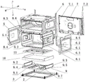
Fig. 6 is an exploded view of the side plate of the cabinet, the rear shelf plate and the cooking cavity according to an embodiment of the present invention.
Fig. 7 is a partially enlarged view of fig. 6.
Fig. 8 is a schematic cross-sectional view of an oven as an electric home appliance according to an embodiment of the present invention.
Fig. 9 is a partially enlarged view of fig. 8.
Fig. 10 is a schematic perspective sectional view of an oven as a household appliance according to an embodiment of the present invention.
Fig. 11 is a partially enlarged view of fig. 10.
Fig. 12 and 14 are schematic structural views of an insulation cotton fixing assembly arranged below a cooking cavity according to an embodiment of the invention.
Fig. 13 and 15 are schematic views illustrating an assembled and disassembled structure of a fixing component of thermal insulation cotton according to an embodiment of the present invention.
Fig. 16 is a schematic perspective sectional view of an insulation wool fixing assembly according to an embodiment of the present invention.
Fig. 17 is a partially enlarged view of fig. 16.
In the figure, 1 is a box body, 2 is a bottom plate of a shell, 2.1 is a mounting hole of a furnace foot, 2.2 is a spiral bulge, 2.3 is a through hole, 3 is the furnace foot, 3.1 is a connecting column, 3.2 is a supporting part, 3.3 is a hexagonal round head, 4 is a door body, 4.1 is a door handle, 5 is a side plate of the box body, 5.1 is a second lower edge, 6 is a limiting plate, 6.1 is a notch, 6.2 is an upper edge of the notch, 6.3 is a side edge of the notch, 7 is a rear frame plate, 7.1 is a first plate body, 7.2 is a convex edge, 7.3 is a convex cavity, 8 is a cooking cavity, 8.1 is a rear wall of the cavity, 8.2 is a bottom wall of the cavity, 8.3 is a top wall of the cavity, 8.4 is a side wall of the cavity, 8.5 is a frame-shaped connecting piece, 8.6 is a cover plate, 8.7 is a second flanging, 8.8.8 is a first lower edge, 9.8 is a supporting plate, 9.1 is a supporting plate, 9.2 is a bottom wall of the supporting plate, 9.9.9.9.9.9 is a left side wall, 9.8 is the backup pad back side wall, 9.9 is the backup pad preceding lateral wall, 9.10 is first turn-ups, 9.11 is the flange, 10 is thermal-insulated cotton, 10.1 is thermal-insulated cotton diapire, 10.2 is thermal-insulated cotton left side wall, 10.3 is thermal-insulated cotton right side wall, 10.4 is thermal-insulated cotton preceding lateral wall, 10.5 is first constant head tank, 10.6 is the second constant head tank, 11 is the heat insulating board, 11.1 is the heat insulating board diapire, 11.2 is the heat insulating board left side wall, 11.3 is the heat insulating board right side wall, 11.4 is the heat insulating board preceding lateral wall, 11.5 is the heat insulating board back side wall.
Detailed Description
The invention is further described with reference to the following figures and examples.
Referring to fig. 1 and 3, the household appliance is an oven, the oven comprises an oven body 1, a shell bottom plate 2 is arranged at the bottom of the oven body 1, a furnace foot 3 is arranged on the shell bottom plate 2, the oven further comprises a door body 4 hinged to the oven body 1, a door handle 4.1 is arranged on the door body 4, a control assembly is arranged on the oven body 1, and the control assembly comprises a knob and a touch control display screen.
Referring to fig. 4 and 5, the spiral bulge 2.2 is arranged on the housing bottom plate 2, the furnace foot 3 comprises a connecting column 3.1 and a supporting part 3.2, the connecting column 3.1 is a threaded column, the spiral bulge 2.2 is provided with a furnace foot mounting hole 2.1 matched with the connecting column 3.1, the connecting column 3.1 penetrates through the furnace foot mounting hole 2.1 of the spiral bulge 2.2, the connecting column 3.1 is in threaded connection with the furnace foot mounting hole 2.1, the furnace foot 3 is detachably connected with the housing bottom plate 2, and the furnace foot 3 is convenient and flexible to detach and replace.
In the embodiment, the shell bottom plate 2 is provided with a through hole 2.3, and the peripheral edge of the through hole 2.3 extends upwards to form a raised spiral bulge 2.2.
Spliced pole 3.1 still includes hexagonal button head 3.3, supporting part 3.2 is located spliced pole 3.1's top, hexagonal button head 3.3 is located spliced pole 3.1's bottom, supporting part 3.2 of stove foot 3, spliced pole 3.1 and hexagonal button head 3.3 integrated into one piece, moreover, the steam generator is simple in structure, convenient production, need not to install other supplementary spare parts when installing the stove foot, save material and installation procedure, simple to operate is simple, furnace foot 3's altitude mixture control is more nimble.
The box body 1 comprises a box body side plate 5, a limiting plate 6 and a rear support plate 7, the box body side plate 5 and/or the rear support plate 7 are/is connected with the limiting plate 6, and the limiting plate 6 is an L-shaped section below the 3-position limiting plate 6 of the furnace foot. The weight of food in the oven and the weight of oven box 1 itself are mainly concentrated on shell bottom plate 2, when shell bottom plate 2 atress was overweight, stove foot mounting hole 2.1 and spiral bulge 2.2 on the shell bottom plate 2 take place to warp easily, the stove foot 3 of installing on stove foot mounting hole 2.1 takes off the gliding phenomenon of loosing to appear, the mounting height of oven descends, be equipped with limiting plate 6 in the top of stove foot 3, the oven height is descending the in-process, supporting part 3.2 and the contact of limiting plate 6 of stove foot 3, and form the secondary support effect to limiting plate 6, prevent that the oven from continuing to descend, reduce the inclination of oven.
Referring to fig. 2, a notch 6.1 is arranged on the limiting plate 6 corresponding to the supporting portion 3.2, the notch 6.1 includes a notch upper edge 6.2 and a notch side edge 6.3, the furnace foot 3 is located in the accommodating space below the notch 6.1, and a certain vertical distance L1 is arranged between the supporting portion 3.2 of the furnace foot 3 and the notch upper edge 6.2.
The limiting plate 6 is provided with a notch 6.1 corresponding to the supporting part 3.2, the supporting part 3.2 and the notch upper edge 6.2 are provided with a certain vertical distance L1, and an enough adjusting space is reserved for the furnace foot 3 in the vertical direction, so that a user can conveniently adjust the height of the furnace foot 3.
Referring to fig. 6-9, the upper surface of the support part 3.2 and the upper edge 6.2 of the notch are both horizontal planes, and the projection of the limiting plate 6 in the vertical direction falls within the area of the upper surface of the support part 3.2.
The projection of limiting plate 6 edge vertical direction is fallen in the area of supporting part 3.2 upper surface, ensure the oven at the decline in-process, limiting plate 6 can contact with supporting part 3.2 of stove foot 3, and simultaneously, the upper surface of supporting part 3.2, the two of border 6.2 is the horizontal plane on the breach, border 6.2's area of contact on increase supporting part 3.2 and the breach, reduce supporting part 3.2's stress, stove foot 3 is more firm to limiting plate 6's supporting role.
Referring to fig. 6, back support plate 7 is located the 1 back of box, back support plate 7 includes first plate body 7.1, be located the first plate body 7.1 left and right sides and protrusion in the stupefied 7.2 of the protruding of first plate body 7.1, the left side of first plate body 7.1, right lower corner department all is equipped with the protruding chamber 7.3 of an holding stove foot 3, the 1 back left and right sides of box all is equipped with limiting plate 6, the stupefied 7.2 of the protruding stupefied 7.2 of the first plate body 7.1 left and right sides is connected with the limiting plate 6 of the 1 back left and right sides of box respectively, the lower limb and the shell bottom plate 2 of back support plate 7 are connected, 5 rear edges of box curb plate are connected with stupefied 7.2 on the back.
In this embodiment, protruding stupefied 7.2 is equipped with spacing mounting groove, and limiting plate 6 assembles on spacing mounting groove.
Referring to fig. 10 and 11, the oven further includes a cooking cavity 8 and a heat insulation cotton fixing component, the cooking cavity 8 includes a cavity back wall 8.1, a cavity bottom wall 8.2, a cavity top wall 8.3 and a cavity side wall 8.4, and the heat insulation cotton fixing component is located below the cooking cavity 8.
Referring to fig. 6, 12 and 14, frame-shaped connecting pieces 8.5 are respectively arranged at the left edge and the right edge of the cavity rear wall 8.1, the rear support plate 7 is fixedly connected with the cavity rear wall 8.1 through the frame-shaped connecting pieces 8.5, a cover plate 8.6 is arranged above the cavity top wall 8.1, and the upper edges of the box side plate 5 and the rear support plate 7 are respectively fixedly connected with the cover plate 8.6.
Referring to fig. 12-17, the insulation wool fixing assembly comprises a support plate 9, insulation wool 10 and a heat insulation board 11, wherein the heat insulation board 11 is mounted on the support plate 9, a containing cavity for fixing the insulation wool 10 is formed between the heat insulation board 11 and the support plate 9, and the insulation wool 10 is fixed in the containing cavity in a limiting manner.
Referring to fig. 12-17, the supporting plate 9 includes a supporting plate bottom wall 9.1, the edge around the supporting plate bottom wall 9.1 extends upwards vertically to form a supporting plate side wall, the supporting plate side wall includes a supporting plate left side wall 9.2 and a supporting plate right side wall 9.3, the supporting plate left side wall 9.2, the supporting plate right side wall 9.3 is provided with a first pressing plate 9.4 and a second pressing plate 9.5 respectively, the first pressing plate 9.4 and the second pressing plate 9.5 are provided with a bending portion 9.6, the bending portion 9.6 is provided with a plurality of oval open holes 9.7, and the first pressing plate 9.4 and the second pressing plate 9.5 are provided with screw holes. The side wall of the supporting plate also comprises a rear side wall 9.8 of the supporting plate and a front side wall 9.9 of the supporting plate, the left side and the right side of the rear side wall 9.8 of the supporting plate are respectively provided with a screw hole,
the heat insulating board 11 includes heat insulating board diapire 11.1, and the vertical extension that makes progress around the heat insulating board diapire 11.1 forms the heat insulating board lateral wall, and the heat insulating board lateral wall includes heat insulating board left side wall 11.2, heat insulating board right side wall 11.3, heat insulating board front side wall 11.4 and heat insulating board back side wall 11.5, and both ends are equipped with the screw hole about the heat insulating board back side wall 11.5, and the place that the heat insulating board diapire 11.1 left and right sides is close to heat insulating board front side wall 11.4 is equipped with a.
In this embodiment, the thermal insulation cotton 10 includes a thermal insulation cotton bottom wall 10.1, and the front edge, the left edge and the right edge of the thermal insulation cotton bottom wall 10.1 respectively extend upwards vertically to form a thermal insulation cotton side wall, and the thermal insulation cotton side wall includes a thermal insulation cotton left side wall 10.2, a thermal insulation cotton right side wall 10.3 and a thermal insulation cotton front side wall 10.4. The heat insulation cotton left side wall 10.2 and the heat insulation cotton right side wall 10.3 are respectively provided with a first positioning groove 10.5 and a second positioning groove 10.6 at the positions close to the heat insulation cotton front side wall 10.4.
During assembly, firstly, the heat insulation cotton 10 is placed on the supporting plate 9, the first pressing plate 9.4 and the second pressing plate 9.5 are respectively bent 90 degrees along the inner side of the bent part 9.6, the first pressing plate 9.4 is pressed on the first positioning groove 10.5, the second pressing plate 9.5 is pressed on the second positioning groove 10.6, the first pressing plate 9.4 and the second pressing plate 9.5 preliminarily press the heat insulation cotton 10, then the heat insulation plate 11 is placed on the heat insulation cotton 10, screw holes of the first pressing plate 9.4, the second pressing plate 9.5 and the bottom wall of the heat insulation plate are aligned and fixedly connected through screws, the rear side wall 11.5 is aligned with screw holes of the rear side wall 9.8 of the supporting plate and fixedly connected through screws, in addition, the front side wall 10.4 of the heat insulation cotton is positioned between the front side wall 11.4 of the heat insulation plate and the front side wall 9.9 of the supporting plate, the bottom wall 10.1 of the heat insulation cotton is positioned between the bottom wall 11.1 of the bottom wall and the supporting plate 9.1, the left side wall 10.2 of the heat insulation plate, the heat insulation cotton right side wall 10.3 is positioned between the heat insulation board right side wall 11.3 and the support board right side wall 9.3 so as to limit the heat insulation cotton 10 in multiple directions such as front, back, up, down, left and right.
The supporting plate 9 is provided with a pressing plate, the heat insulation cotton 10 can be preliminarily fixed through bending the pressing plate, and in the assembling process, the heat insulation cotton 10 is not easy to turn upwards, so that the subsequent installation of the heat insulation board 11 is facilitated; an oval opening 9.7 is formed in the bending part 9.6 of the pressing plate, so that staff can conveniently bend the pressing plate; the pressing plate is provided with a screw hole, and after the pressing plate is bent by 90 degrees, a supporting plane and a fixing part can be provided for the heat insulation plate 11 and are used for supporting and fixing the heat insulation plate 11; the pressing plate and the supporting plate 9 are integrally formed, so that the assembling process of the pressing plate is saved, and the assembling efficiency is improved.
The heat insulating board 11 and the supporting plate 9 are both provided with a bottom wall and peripheral side walls, after the assembly is completed, the bottom walls and the peripheral side walls of the heat insulating board 11 and the supporting plate 9 are both limited in a plurality of directions such as front, back, left, right, upper and lower directions, the heat insulating cotton 10 is effectively prevented from falling off or turning over, and the heat insulating cotton 10 is firmly installed.
This mounting structure can place more thickened thermal-insulated cotton 10, when thermal-insulated cotton 10's thickness is greater than the clearance between backup pad 9 and the heat insulating board 11, because thermal-insulated cotton 10 is soft, at the in-process of installation thermal-insulated cotton 10, heat insulating cotton 10 can be extruded to clamp plate and heat insulating board 11, thermal-insulated cotton 10 interference fit between heat insulating board 11 and backup pad 9, the installation is more firm, and thermal-insulated cotton 10 thickness increases the back, thermal-insulated cotton 10's the heat preservation effect is better with thermal-insulated effect.
The heat insulation cotton fixing component is flexible and convenient to assemble, a worker can assemble the support plate 9, the heat insulation cotton 10 and the heat insulation plate 11 at first, and then the assembled heat insulation cotton fixing component is stored and subsequently installed as an independent component, so that the worker can flexibly arrange production.
Supporting plate left side wall 9.2, be equipped with first turn-ups 9.10 on the backup pad right side wall 9.3 respectively, be equipped with second turn-ups 8.7 on the 8.2 left and right sides of cavity diapire respectively, first turn-ups 9.10 and second turn-ups 8.7 are connected, be equipped with the first border 8.8 of connecting backup pad rear wall 9.8 on the cavity rear wall 8.1, be equipped with second border 5.1 down on the box curb plate 5, supporting plate left side wall 9.2, still be equipped with respectively on the backup pad right side wall 9.3 and connect the limit 9.11 continuous with second border 5.1 down.
In this embodiment, the fixing connection manner is welding or fixing connection by screws or buckles.
The foregoing is a preferred embodiment of the present invention, and the basic principles, principal features and advantages of the invention are shown and described. It will be understood by those skilled in the art that the present invention is not limited to the embodiments described above, which are intended to illustrate the principles of the invention, but that various changes and modifications may be made without departing from the spirit and scope of the invention, and the invention is intended to be protected by the following claims. The scope of the invention is defined by the appended claims and equivalents thereof.
Claims (10)
1. The utility model provides a household appliance, includes box (1), supports household appliance's stove foot (3), its characterized in that: in the installation height direction of the household appliance, the box body (1) is provided with a limiting plate (6), the stove feet (3) are positioned below the limiting plate (6), and the limiting plate (6) is partially contacted with the stove feet (3) in the descending process of the installation height of the household appliance.
2. The household appliance according to claim 1, wherein: limiting plate (6) are equipped with breach (6.1) on the position of contact stove foot (3), breach (6.1) are including breach upper limb (6.2), a accommodation space is formed below breach (6.1), stove foot (3) are located this accommodation space, breach upper limb (6.2) are in the electrical apparatus mounted height decline in-process and are contacted with stove foot (3), stove foot (3) are including supporting part (3.2), be equipped with vertical interval L1 between border (6.2) on supporting part (3.2) and the breach.
3. The household appliance according to claim 2, wherein: the upper surface of the supporting part (3.2) and the upper edge (6.2) of the notch are both horizontal planes, and the projection of the limiting plate (6) along the vertical direction falls in the area of the upper surface of the supporting part (3.2).
4. A household appliance as claimed in any one of claims 1 to 3, characterized in that: the furnace foot (3) also comprises a connecting column (3.1) and a hexagonal round head (3.3), and the connecting column (3.1), the supporting part (3.2) and the hexagonal round head (3.3) on the furnace foot (3) are integrally formed; the box (1) comprises a shell bottom plate (2), a through hole (2.3) is formed in the shell bottom plate (2), the periphery of the through hole (2.3) extends upwards to form a raised spiral bulge (2.2), a furnace foot mounting hole (2.1) matched with a connecting column (3.1) is formed in the spiral bulge (2.2), and the furnace foot (3) is detachably mounted on the shell bottom plate (2) through the furnace foot mounting hole (2.1).
5. The household appliance according to claim 4, wherein: the box body (1) comprises a rear support plate (7), the rear support plate (7) comprises a first plate body (7.1) and a protruding edge (7.2) protruding out of the first plate body (7.1), a convex cavity (7.3) for accommodating the furnace foot (3) is arranged on the first plate body (7.1), and a limiting plate (6) and the protruding edge (7.2) on the box body (1) are fixedly connected.
6. A household appliance as claimed in any one of claims 1 to 3, characterized in that: the household appliance is an oven which comprises a cooking cavity (8), and a heat insulation cotton fixing component is arranged below the cooking cavity (8).
7. The household appliance according to claim 6, wherein: the cooking cavity (8) comprises a cavity rear wall (8.1) and a cavity top wall (8.3), the box body (1) comprises a box body side plate (5) and a rear support plate (7), and a frame-shaped connecting piece (8.5) used for connecting the rear support plate (7) is arranged on the cavity rear wall (8.1); a cover plate (8.6) is arranged above the top wall (8.3) of the cavity, and the upper edges of the box body side plate (5) and the rear support plate (7) are respectively connected with the cover plate (8.6).
8. The household appliance according to claim 6, wherein: the heat insulation cotton fixing component comprises a supporting plate (9), heat insulation cotton (10) and a heat insulation board (11), the heat insulation board (11) is installed on the supporting plate (9), an accommodating cavity for fixing the heat insulation cotton (10) is formed between the heat insulation board (11) and the supporting plate (9), a limiting part and a fixing part are arranged between the heat insulation board (11) and the supporting plate (9), and the heat insulation cotton (10) is limited and fixed in the accommodating cavity through the limiting part and the fixing part; the heat insulation board (11) comprises a heat insulation board bottom wall (11.1), the fixing part comprises a pressing plate arranged on the supporting plate (9), a positioning groove is formed in the heat insulation cotton (10) corresponding to the pressing plate, the pressing plate is arranged on the positioning groove in a pressing mode through bending, and the heat insulation board bottom wall (11.1) is in contact with the pressing plate; in addition, the press plate after bending is fixedly connected with the bottom wall (11.1) of the heat insulation plate, the limiting part comprises the bottom walls and the peripheral side walls of the heat insulation plate (11) and the support plate (9), the bottom wall of the heat insulation cotton (10) is located between the bottom walls of the heat insulation plate (11) and the support plate (9), the peripheral side of the heat insulation cotton (10) is located between the peripheral side walls of the heat insulation plate (11) and the support plate (9), and the heat insulation cotton (10) is limited in the front, back, left, right, upper and lower directions.
9. The household appliance according to claim 8, wherein: the clamp plate includes first clamp plate (9.4) and second clamp plate (9.5), the constant head tank of thermal-insulated cotton (10) includes first constant head tank (10.5), second constant head tank (10.6), all be equipped with portion of bending (9.6) on first clamp plate (9.4) and second clamp plate (9.5), be equipped with a plurality of trompil (9.7) on portion of bending (9.6), first clamp plate (9.4) and second clamp plate (9.5) are bent and are then pressed and establish first constant head tank (10.5) along portion of bending (9.6) respectively, second constant head tank (10.6), interference fit or clearance fit between heat insulating board (11) and backup pad (9) thermal-insulated cotton (10).
10. The household appliance according to claim 9, wherein: the cooking cavity (8) further comprises a cavity bottom wall (8.2), a supporting plate left side wall (9.2), a supporting plate right side wall (9.3) and a supporting plate rear side wall (9.8) are arranged on the supporting plate (9), first turned-over edges (9.10) are arranged on the supporting plate left side wall (9.2) and the supporting plate right side wall (9.3) respectively, second turned-over edges (8.7) are arranged on the left side and the right side of the cavity bottom wall (8.2) respectively, the first turned-over edges (9.10) are connected with the second turned-over edges (8.7), first lower edges (8.8) for connecting the supporting plate rear side walls (9.8) are arranged on the cavity rear side wall (8.1), second lower edges (5.1) are arranged on the box side plate (5), connecting edges (9.11) connected with the second lower edges (5.1) are further arranged on the supporting plate left side wall (9.2) and the supporting plate right.
Priority Applications (1)
| Application Number | Priority Date | Filing Date | Title |
|---|---|---|---|
| CN202011232946.2A CN112353263B (en) | 2020-11-06 | 2020-11-06 | Household appliance |
Applications Claiming Priority (1)
| Application Number | Priority Date | Filing Date | Title |
|---|---|---|---|
| CN202011232946.2A CN112353263B (en) | 2020-11-06 | 2020-11-06 | Household appliance |
Publications (2)
| Publication Number | Publication Date |
|---|---|
| CN112353263A true CN112353263A (en) | 2021-02-12 |
| CN112353263B CN112353263B (en) | 2021-10-08 |
Family
ID=74509747
Family Applications (1)
| Application Number | Title | Priority Date | Filing Date |
|---|---|---|---|
| CN202011232946.2A Active CN112353263B (en) | 2020-11-06 | 2020-11-06 | Household appliance |
Country Status (1)
| Country | Link |
|---|---|
| CN (1) | CN112353263B (en) |
Citations (12)
| Publication number | Priority date | Publication date | Assignee | Title |
|---|---|---|---|---|
| CN1704686A (en) * | 2004-05-27 | 2005-12-07 | 乐金电子(天津)电器有限公司 | Gridiron for microwave oven |
| CN101796241A (en) * | 2007-09-03 | 2010-08-04 | Lg电子株式会社 | Supporter and pedestal and washing/drying machine having the same |
| CN204600243U (en) * | 2015-04-23 | 2015-09-02 | 广东依信嘉电气实业有限公司 | A kind of lift baking oven stage apparatus |
| CN106889793A (en) * | 2017-04-10 | 2017-06-27 | 成都大唐弘伟木业有限公司 | Furniture height regulator |
| CN108720646A (en) * | 2018-06-26 | 2018-11-02 | 张大伟 | A kind of environmentally friendly carbon oven being convenient to clean |
| CN209003896U (en) * | 2018-04-19 | 2019-06-21 | 广东格兰仕集团有限公司 | The mounting structure of dish-washing machine skirting board |
| CN209300879U (en) * | 2018-07-18 | 2019-08-27 | 佛山市禅城区皓达电子有限公司 | A kind of support construction of Roaster structure |
| CN110834917A (en) * | 2019-11-12 | 2020-02-25 | 徐州奥鹏矿山设备有限公司 | Mining height-adjustable conveyer belt |
| CN111101794A (en) * | 2020-01-13 | 2020-05-05 | 浙江蓝炬星电器有限公司 | Anti-deformation supporting structure for box door of steaming and baking box and mounting method of anti-deformation supporting structure |
| CN111493685A (en) * | 2020-04-30 | 2020-08-07 | 祁新纪 | Electric oven |
| CN111816399A (en) * | 2020-07-01 | 2020-10-23 | 海盐伟佳电器科技有限公司 | Overload-resistant manganin resistor production line and production process thereof |
| CN211834010U (en) * | 2019-12-28 | 2020-11-03 | 上海东光厨房设备有限公司 | Electric oven capable of baking uniformly |
-
2020
- 2020-11-06 CN CN202011232946.2A patent/CN112353263B/en active Active
Patent Citations (12)
| Publication number | Priority date | Publication date | Assignee | Title |
|---|---|---|---|---|
| CN1704686A (en) * | 2004-05-27 | 2005-12-07 | 乐金电子(天津)电器有限公司 | Gridiron for microwave oven |
| CN101796241A (en) * | 2007-09-03 | 2010-08-04 | Lg电子株式会社 | Supporter and pedestal and washing/drying machine having the same |
| CN204600243U (en) * | 2015-04-23 | 2015-09-02 | 广东依信嘉电气实业有限公司 | A kind of lift baking oven stage apparatus |
| CN106889793A (en) * | 2017-04-10 | 2017-06-27 | 成都大唐弘伟木业有限公司 | Furniture height regulator |
| CN209003896U (en) * | 2018-04-19 | 2019-06-21 | 广东格兰仕集团有限公司 | The mounting structure of dish-washing machine skirting board |
| CN108720646A (en) * | 2018-06-26 | 2018-11-02 | 张大伟 | A kind of environmentally friendly carbon oven being convenient to clean |
| CN209300879U (en) * | 2018-07-18 | 2019-08-27 | 佛山市禅城区皓达电子有限公司 | A kind of support construction of Roaster structure |
| CN110834917A (en) * | 2019-11-12 | 2020-02-25 | 徐州奥鹏矿山设备有限公司 | Mining height-adjustable conveyer belt |
| CN211834010U (en) * | 2019-12-28 | 2020-11-03 | 上海东光厨房设备有限公司 | Electric oven capable of baking uniformly |
| CN111101794A (en) * | 2020-01-13 | 2020-05-05 | 浙江蓝炬星电器有限公司 | Anti-deformation supporting structure for box door of steaming and baking box and mounting method of anti-deformation supporting structure |
| CN111493685A (en) * | 2020-04-30 | 2020-08-07 | 祁新纪 | Electric oven |
| CN111816399A (en) * | 2020-07-01 | 2020-10-23 | 海盐伟佳电器科技有限公司 | Overload-resistant manganin resistor production line and production process thereof |
Also Published As
| Publication number | Publication date |
|---|---|
| CN112353263B (en) | 2021-10-08 |
Similar Documents
| Publication | Publication Date | Title |
|---|---|---|
| CN112353263B (en) | Household appliance | |
| US6888107B2 (en) | One-piece burner element/switch support for a cooktop | |
| CN109717726B (en) | Portable multifunctional cooker | |
| EP4039140B1 (en) | Air fryer having broiling and baking functions | |
| CN210204505U (en) | Baking tray assembly and baking machine thereof | |
| KR100958843B1 (en) | electric grill | |
| CN210921499U (en) | Household multifunctional heating machine | |
| CN219269098U (en) | Graphene heating oven | |
| CN218154351U (en) | Cooking utensil | |
| CN211408715U (en) | Cooking utensil | |
| CN221511658U (en) | Bakeware and oven | |
| CN215016276U (en) | Heat insulation cotton fixing structure and cooking appliance thereof | |
| CN219940320U (en) | Steam cooking equipment and water box assembly thereof | |
| CN218074019U (en) | Electric heating table and table thereof | |
| CN220876570U (en) | Multifunctional food heating electric appliance | |
| CN220158116U (en) | Multifunctional cooking stove | |
| CN220275436U (en) | Intelligent oven | |
| CN220369865U (en) | Heating mechanism and cooking utensil | |
| CN219982697U (en) | Temperature controller mounting structure and electric chafing dish comprising same | |
| CN219069971U (en) | Novel trinity gridiron | |
| CN217852416U (en) | Roast integrative pot of rinsing | |
| CN216876051U (en) | Integrated cavity and steam oven comprising same | |
| CN211911373U (en) | Standing type electric oven | |
| CN221122316U (en) | Kitchen range bottom shell | |
| CN214387217U (en) | Cooking utensil |
Legal Events
| Date | Code | Title | Description |
|---|---|---|---|
| PB01 | Publication | ||
| PB01 | Publication | ||
| SE01 | Entry into force of request for substantive examination | ||
| SE01 | Entry into force of request for substantive examination | ||
| GR01 | Patent grant | ||
| GR01 | Patent grant |