CN112350451A - Inductive charging between electronic devices - Google Patents
Inductive charging between electronic devices Download PDFInfo
- Publication number
- CN112350451A CN112350451A CN202011179540.2A CN202011179540A CN112350451A CN 112350451 A CN112350451 A CN 112350451A CN 202011179540 A CN202011179540 A CN 202011179540A CN 112350451 A CN112350451 A CN 112350451A
- Authority
- CN
- China
- Prior art keywords
- electronic device
- housing
- inductive
- power
- coil
- Prior art date
- Legal status (The legal status is an assumption and is not a legal conclusion. Google has not performed a legal analysis and makes no representation as to the accuracy of the status listed.)
- Pending
Links
- 230000001939 inductive effect Effects 0.000 title claims abstract description 375
- 230000006698 induction Effects 0.000 claims abstract description 220
- 238000004891 communication Methods 0.000 claims description 78
- 238000012546 transfer Methods 0.000 claims description 56
- 230000005540 biological transmission Effects 0.000 claims description 26
- 230000001681 protective effect Effects 0.000 claims description 7
- 230000004044 response Effects 0.000 claims description 7
- 230000003213 activating effect Effects 0.000 claims 4
- 238000004804 winding Methods 0.000 claims 2
- 238000000034 method Methods 0.000 abstract description 14
- 230000000670 limiting effect Effects 0.000 description 57
- 230000008878 coupling Effects 0.000 description 28
- 238000010168 coupling process Methods 0.000 description 28
- 238000005859 coupling reaction Methods 0.000 description 28
- 238000005516 engineering process Methods 0.000 description 12
- 239000000463 material Substances 0.000 description 12
- 230000001965 increasing effect Effects 0.000 description 8
- 230000036541 health Effects 0.000 description 7
- 230000008569 process Effects 0.000 description 7
- 230000003247 decreasing effect Effects 0.000 description 5
- 230000002829 reductive effect Effects 0.000 description 5
- 239000002184 metal Substances 0.000 description 4
- 229910052751 metal Inorganic materials 0.000 description 4
- 230000000007 visual effect Effects 0.000 description 4
- 230000002452 interceptive effect Effects 0.000 description 3
- 239000004033 plastic Substances 0.000 description 3
- 239000004020 conductor Substances 0.000 description 2
- 230000007423 decrease Effects 0.000 description 2
- 238000010586 diagram Methods 0.000 description 2
- 238000005401 electroluminescence Methods 0.000 description 2
- 239000011521 glass Substances 0.000 description 2
- 239000004973 liquid crystal related substance Substances 0.000 description 2
- 238000012986 modification Methods 0.000 description 2
- 230000004048 modification Effects 0.000 description 2
- 238000012806 monitoring device Methods 0.000 description 2
- 238000012545 processing Methods 0.000 description 2
- 229910052594 sapphire Inorganic materials 0.000 description 2
- 239000010980 sapphire Substances 0.000 description 2
- 239000000758 substrate Substances 0.000 description 2
- OKTJSMMVPCPJKN-UHFFFAOYSA-N Carbon Chemical compound [C] OKTJSMMVPCPJKN-UHFFFAOYSA-N 0.000 description 1
- QVGXLLKOCUKJST-UHFFFAOYSA-N atomic oxygen Chemical compound [O] QVGXLLKOCUKJST-UHFFFAOYSA-N 0.000 description 1
- 230000036772 blood pressure Effects 0.000 description 1
- 229910052799 carbon Inorganic materials 0.000 description 1
- 239000002131 composite material Substances 0.000 description 1
- 238000011109 contamination Methods 0.000 description 1
- 230000037213 diet Effects 0.000 description 1
- 235000005911 diet Nutrition 0.000 description 1
- 229920001971 elastomer Polymers 0.000 description 1
- 239000000806 elastomer Substances 0.000 description 1
- 238000004519 manufacturing process Methods 0.000 description 1
- 238000005259 measurement Methods 0.000 description 1
- 150000002739 metals Chemical class 0.000 description 1
- 230000035764 nutrition Effects 0.000 description 1
- 235000016709 nutrition Nutrition 0.000 description 1
- 229910052760 oxygen Inorganic materials 0.000 description 1
- 239000001301 oxygen Substances 0.000 description 1
- 238000003825 pressing Methods 0.000 description 1
- 230000035939 shock Effects 0.000 description 1
- XLYOFNOQVPJJNP-UHFFFAOYSA-N water Substances O XLYOFNOQVPJJNP-UHFFFAOYSA-N 0.000 description 1
- 210000000707 wrist Anatomy 0.000 description 1
Images


Classifications
-
- H02J5/005—
-
- H—ELECTRICITY
- H02—GENERATION; CONVERSION OR DISTRIBUTION OF ELECTRIC POWER
- H02J—CIRCUIT ARRANGEMENTS OR SYSTEMS FOR SUPPLYING OR DISTRIBUTING ELECTRIC POWER; SYSTEMS FOR STORING ELECTRIC ENERGY
- H02J50/00—Circuit arrangements or systems for wireless supply or distribution of electric power
- H02J50/10—Circuit arrangements or systems for wireless supply or distribution of electric power using inductive coupling
-
- G—PHYSICS
- G06—COMPUTING; CALCULATING OR COUNTING
- G06F—ELECTRIC DIGITAL DATA PROCESSING
- G06F1/00—Details not covered by groups G06F3/00 - G06F13/00 and G06F21/00
- G06F1/26—Power supply means, e.g. regulation thereof
- G06F1/266—Arrangements to supply power to external peripherals either directly from the computer or under computer control, e.g. supply of power through the communication port, computer controlled power-strips
-
- G—PHYSICS
- G06—COMPUTING; CALCULATING OR COUNTING
- G06F—ELECTRIC DIGITAL DATA PROCESSING
- G06F3/00—Input arrangements for transferring data to be processed into a form capable of being handled by the computer; Output arrangements for transferring data from processing unit to output unit, e.g. interface arrangements
- G06F3/01—Input arrangements or combined input and output arrangements for interaction between user and computer
- G06F3/03—Arrangements for converting the position or the displacement of a member into a coded form
- G06F3/041—Digitisers, e.g. for touch screens or touch pads, characterised by the transducing means
-
- H—ELECTRICITY
- H01—ELECTRIC ELEMENTS
- H01F—MAGNETS; INDUCTANCES; TRANSFORMERS; SELECTION OF MATERIALS FOR THEIR MAGNETIC PROPERTIES
- H01F38/00—Adaptations of transformers or inductances for specific applications or functions
- H01F38/14—Inductive couplings
-
- H—ELECTRICITY
- H02—GENERATION; CONVERSION OR DISTRIBUTION OF ELECTRIC POWER
- H02J—CIRCUIT ARRANGEMENTS OR SYSTEMS FOR SUPPLYING OR DISTRIBUTING ELECTRIC POWER; SYSTEMS FOR STORING ELECTRIC ENERGY
- H02J50/00—Circuit arrangements or systems for wireless supply or distribution of electric power
- H02J50/90—Circuit arrangements or systems for wireless supply or distribution of electric power involving detection or optimisation of position, e.g. alignment
-
- H—ELECTRICITY
- H02—GENERATION; CONVERSION OR DISTRIBUTION OF ELECTRIC POWER
- H02J—CIRCUIT ARRANGEMENTS OR SYSTEMS FOR SUPPLYING OR DISTRIBUTING ELECTRIC POWER; SYSTEMS FOR STORING ELECTRIC ENERGY
- H02J7/00—Circuit arrangements for charging or depolarising batteries or for supplying loads from batteries
- H02J7/0042—Circuit arrangements for charging or depolarising batteries or for supplying loads from batteries characterised by the mechanical construction
-
- H02J7/025—
-
- H—ELECTRICITY
- H02—GENERATION; CONVERSION OR DISTRIBUTION OF ELECTRIC POWER
- H02J—CIRCUIT ARRANGEMENTS OR SYSTEMS FOR SUPPLYING OR DISTRIBUTING ELECTRIC POWER; SYSTEMS FOR STORING ELECTRIC ENERGY
- H02J7/00—Circuit arrangements for charging or depolarising batteries or for supplying loads from batteries
- H02J7/34—Parallel operation in networks using both storage and other dc sources, e.g. providing buffering
- H02J7/342—The other DC source being a battery actively interacting with the first one, i.e. battery to battery charging
-
- H—ELECTRICITY
- H04—ELECTRIC COMMUNICATION TECHNIQUE
- H04M—TELEPHONIC COMMUNICATION
- H04M1/00—Substation equipment, e.g. for use by subscribers
- H04M1/72—Mobile telephones; Cordless telephones, i.e. devices for establishing wireless links to base stations without route selection
- H04M1/724—User interfaces specially adapted for cordless or mobile telephones
- H04M1/72403—User interfaces specially adapted for cordless or mobile telephones with means for local support of applications that increase the functionality
- H04M1/72409—User interfaces specially adapted for cordless or mobile telephones with means for local support of applications that increase the functionality by interfacing with external accessories
- H04M1/72412—User interfaces specially adapted for cordless or mobile telephones with means for local support of applications that increase the functionality by interfacing with external accessories using two-way short-range wireless interfaces
-
- H—ELECTRICITY
- H02—GENERATION; CONVERSION OR DISTRIBUTION OF ELECTRIC POWER
- H02J—CIRCUIT ARRANGEMENTS OR SYSTEMS FOR SUPPLYING OR DISTRIBUTING ELECTRIC POWER; SYSTEMS FOR STORING ELECTRIC ENERGY
- H02J2207/00—Indexing scheme relating to details of circuit arrangements for charging or depolarising batteries or for supplying loads from batteries
- H02J2207/20—Charging or discharging characterised by the power electronics converter
-
- H—ELECTRICITY
- H02—GENERATION; CONVERSION OR DISTRIBUTION OF ELECTRIC POWER
- H02J—CIRCUIT ARRANGEMENTS OR SYSTEMS FOR SUPPLYING OR DISTRIBUTING ELECTRIC POWER; SYSTEMS FOR STORING ELECTRIC ENERGY
- H02J2310/00—The network for supplying or distributing electric power characterised by its spatial reach or by the load
- H02J2310/10—The network having a local or delimited stationary reach
- H02J2310/20—The network being internal to a load
- H02J2310/22—The load being a portable electronic device
Landscapes
- Engineering & Computer Science (AREA)
- Power Engineering (AREA)
- General Engineering & Computer Science (AREA)
- Theoretical Computer Science (AREA)
- Computer Networks & Wireless Communication (AREA)
- Physics & Mathematics (AREA)
- General Physics & Mathematics (AREA)
- Computer Hardware Design (AREA)
- Human Computer Interaction (AREA)
- Signal Processing (AREA)
- Charge And Discharge Circuits For Batteries Or The Like (AREA)
Abstract
The present disclosure relates to inductive charging between electronic devices. An electronic device and method for inductively charging an electronic device with another external electronic device are disclosed. The electronic device may include a housing, a battery positioned within the housing, and an induction coil coupled to the battery. The induction coil may have two or more modes of operation, including a power receiving mode of operation for wirelessly receiving power, and a power transmitting mode of operation for wirelessly transmitting power. The electronic device may also have a controller coupled to the inductive coil for selecting one of the operating modes.
Description
This application is a divisional application of the invention patent application having an application date of 2015, 9/17, application number of 201580046364.6, entitled "inductive charging between electronic devices".
Cross Reference to Related Applications
This patent cooperation treaty patent application claims priority from U.S. provisional patent application 62/056,827 entitled "Inductive Charging Between Electronic Devices" filed on 29.9.2014 and U.S. non-provisional patent application 14/731,280 entitled "Inductive Charging Between Electronic Devices" filed on 4.6.2015, the contents of both of which are incorporated herein by reference in their entirety.
Technical Field
The present disclosure relates generally to electronic devices, and more particularly to wirelessly charging a first electronic device with a second electronic device.
Background
Some electronic devices include one or more rechargeable batteries that may require an external power source for recharging. These devices can often be charged using common or standardized electrical connectors or cables. For example, some devices may be charged using a universal serial bus ("USB") connector or cable. However, despite having standardized connectors and cables, each device may require a separate or dedicated power source to charge. In some cases, having separate power sources for each device may be burdensome to use, store, and/or transport.
Disclosure of Invention
In general, embodiments discussed herein relate to an electronic device configured to inductively or wirelessly transfer power to a second external electronic device. The wireless power transfer may be used to charge a battery of the first electronic device and/or the second electronic device. The electronic device may include an induction coil that may be configured to be in electronic communication with an induction coil of an external electronic device. In some embodiments, an electrically communicative inductive coil may serve as a transmission coil and/or a reception coil capable of transmitting power between electronic devices. Such power transfer may increase the charge of a battery of the electronic device receiving the power while decreasing the charge of a battery transferring the power. An induction coil of an electronic device capable of transferring power to an external electronic device may allow charging a battery of the electronic device with only another electronic device. As such, only a single cable or no cable may be required to charge one or more devices in a group of devices that include an electrically communicated induction coil.
Some example embodiments relate to a portable electronic device that includes a housing defining an opening, a display positioned or disposed within the opening, a user input device positioned on an exterior surface of the display, and a battery positioned in or on the housing. The battery may be configured to provide power to the display. The device may also include a transmission induction coil within the housing and configured to wirelessly transmit power to an external device positioned proximate to the housing. In some embodiments, the transmitting inductive coil is operatively coupled to a battery and configured to wirelessly transmit power from the battery to an external device. In some embodiments, the device further comprises a receiving inductive coil positioned or disposed within the housing and configured to wirelessly receive power from an external device positioned proximate to the housing. In some embodiments, the portable electronic device includes a speaker within the housing and electrically coupled to the battery. The portable electronic device may also include a microphone within the housing and electrically coupled to the battery. In some cases, the user input device is a touch sensor or touch screen positioned on an exterior surface of the device.
Some example embodiments relate to an electronic device including a housing, a battery within the housing, and an induction coil within the housing and coupled to the battery. The induction coil may be configured to operate in two or more modes of operation, including: a power receiving mode for wirelessly receiving power from an external device; and a power transmission mode for wirelessly transmitting power to the external device. The device may also include a controller coupled to the inductive coil and configured to select an operating mode of the inductive coil. In some cases, the controller is in electronic communication with the battery and is configured to monitor a charge of the battery. In some embodiments, the device may include a display, a touch sensor, a speaker disposed or positioned within the housing and electrically coupled to the battery, and a microphone disposed or positioned within the housing and electrically coupled to the battery.
In some embodiments, the induction coil is an inner induction coil, and the apparatus comprises an outer induction coil surrounding the inner induction coil. In some cases, when in the power transfer mode, both the inner and outer inductive coils are activated to transfer wireless power. In some cases, when in the power receiving mode, only the inner inductive coil is activated to receive wireless power.
In some embodiments, the electronic device includes an alignment magnet positioned adjacent to the induction coil. The alignment magnet may be configured to assist in positioning the external device relative to the electronic device.
In some embodiments, the electronic device is one of: a first mobile phone, a first smartphone, a first tablet, or a first notebook, and the external device is one of: a second mobile phone, a second smartphone, a second tablet, or a second laptop.
In some embodiments, a battery of the electronic device is configured to be charged by an external device while in the power receiving mode. In some embodiments, a battery of the electronic device is configured to charge an external device while in the power transfer mode.
Some example embodiments relate to a method of inductively wirelessly coupling a first electronic device and a second electronic device. The first inductive coil of the first electronic device may be positioned relative to the second inductive coil of the second electronic device. Using a first controller of the first electronic device, an operating mode of the first inductive coil may be selected. The first inductive coil may be configured to operate in two or more modes of operation, including: a power receiving mode of operation for wirelessly receiving power; and a power transfer mode for wirelessly transferring power. The method may further include transmitting power from one of: from the first induction coil to the second induction coil, or from the second induction coil to the first induction coil. In some embodiments, a second controller of a second electronic device is utilized to select an operating mode of a second inductive coil of the second electronic device.
In some embodiments, positioning the first inductive coil relative to the second inductive coil includes positioning the first electronic device directly on the second electronic device, and aligning the first inductive coil of the first electronic device with the second inductive coil of the second electronic device. In some embodiments, positioning the first inductive coil relative to the second inductive coil includes coupling a first alignment magnet of the first electronic device to a second alignment magnet of the second electronic device. The first alignment magnet may be positioned adjacent to the first induction coil, and the second alignment magnet may be positioned adjacent to the second induction coil.
In some embodiments, selecting the operating mode of the first induction coil comprises: the method further includes detecting a presence of a second electronic device, and selecting an operating mode of the first inductive coil in response to detecting the presence of the second electronic device.
In some embodiments, an outer inductive coil of a first electronic device is activated to wirelessly couple power with a second coil of a second electronic device, the outer inductive coil may surround the first inductive coil. In some cases, a power coupling efficiency is estimated between a first inductive coil of a first device and a second inductive coil of a second electronic device while power is transferred from the first inductive coil to the second inductive coil. In some cases, an outer induction coil surrounding the first induction coil is activated based on the estimation.
Some example embodiments relate to a system including a first electronic device and a second electronic device. The first electronic device may include a first battery, a first inductive coil coupled to the first battery, and a first controller coupled to the first inductive coil to select an operating mode of the first inductive coil. A second electronic device may be positioned adjacent to the first electronic device. The second electronic device may include a second battery, a second inductive coil coupled to the second battery, and a second controller coupled to the second inductive coil for selecting an operating mode of the second inductive coil. In some cases, the first controller is configured to select a power transfer mode of operation for wirelessly transferring power from the first battery to the second battery using the first inductive coil. The first controller may be further configured to select a power receiving operation mode for wirelessly receiving power from the second battery to the first battery using the first induction coil.
In some embodiments, the first electronic device includes a first alignment magnet positioned adjacent to the first induction coil. In some embodiments, the second electronic device includes a second alignment magnet positioned adjacent to the second inductive coil. The second alignment magnet may be configured to attract the first alignment magnet to align the first inductive coil of the first electronic device with the second inductive coil of the second electronic device.
In some embodiments, the first electronic device includes an outer inductive coil surrounding the first inductive coil. The outer inductive coil may be coupled to the first battery and the first controller. In some embodiments, the second electronic device includes a second outer inductive coil surrounding the second inductive coil. The second outer inductive coil may be coupled to a second battery and a second controller. In some cases, the first inductive coil of the first electronic device is configured to wirelessly transfer power with at least one of: a second inductive coil of a second electronic device, and a second outer inductive coil of the second electronic device. The outer inductive coil of the first electronic device may be configured to wirelessly transfer power with at least one of: a second inductive coil of a second electronic device, and a second outer inductive coil of the second electronic device.
In some embodiments, the first electronic device further comprises a display, and the first electronic device is configured to modify a graphical output of the display in response to the first electronic device being proximate to the second electronic device. In some cases, the graphical output of the display indicates an alignment of the first electronic device relative to the second electronic device.
Drawings
The present disclosure will be readily understood by the following detailed description in conjunction with the accompanying drawings, wherein like reference numerals designate like structural elements, and in which:
fig. 1 shows an illustrative front view of a first electronic device including an induction coil, according to an embodiment;
fig. 2 shows an illustrative view of the first electronic device of fig. 1 with the display removed, in accordance with an embodiment;
fig. 3 shows an illustrative rear view of the first electronic device of fig. 1, in accordance with an embodiment;
4A-4C show illustrative side cross-sectional views of a portion of the first electronic device of FIG. 1 taken along line 4-4 according to embodiments;
fig. 5A shows an illustrative front view of a second electronic device including a set of inductive coils, according to an embodiment;
fig. 5B shows an illustrative rear view of the second electronic device of fig. 5A, according to an embodiment;
fig. 6A shows an illustrative front view of a third electronic device including an induction coil, in accordance with an embodiment;
fig. 6B shows an illustrative rear view of the third electronic device of fig. 6A, according to an embodiment;
fig. 7A shows an illustrative top view of a fourth electronic device including a set of inductive coils, according to an embodiment;
fig. 7B shows an illustrative top view of the fourth electronic device of fig. 7A in a closed configuration, in accordance with embodiments;
fig. 8 shows an illustrative front view of a fifth electronic device according to an embodiment;
fig. 9A shows an illustrative view of the first electronic device of fig. 1 inserted into a fifth electronic device according to claim 8, in accordance with some embodiments;
fig. 9B shows an illustrative front view of the first electronic device of fig. 1 positioned within the fifth electronic device of fig. 5A, according to an embodiment;
fig. 10 shows an illustrative front view of the first electronic device of fig. 1 positioned adjacent to the second electronic device of fig. 5A, in accordance with an embodiment;
FIG. 11 shows an illustrative side cross-sectional view of a portion of the first electronic device of FIG. 1 and the second electronic device of FIG. 5A taken along line 11-11 of FIG. 10 according to an embodiment;
fig. 12 shows an illustrative front view of the first electronic device of fig. 1 positioned adjacent to the second electronic device of fig. 5A in accordance with further embodiments;
fig. 13 shows an illustrative front view of the first electronic device of fig. 1 and the third electronic device of fig. 6A positioned adjacent to the second electronic device of fig. 5A, in accordance with an embodiment;
fig. 14 shows an illustrative front view of the first electronic device of fig. 1 and the third electronic device of fig. 6A positioned adjacent to the second electronic device of fig. 5A, according to an embodiment;
fig. 15 shows an illustrative front view of the first electronic device of fig. 1 positioned adjacent to the fourth electronic device of fig. 7A, in accordance with an embodiment;
fig. 16 shows an illustrative front view of the first electronic device of fig. 1 positioned adjacent to the fourth electronic device of fig. 7A, in accordance with an embodiment;
fig. 17 shows an illustrative front view of the first electronic device of fig. 1 and the third electronic device of fig. 6A positioned adjacent to the fourth electronic device of fig. 7A, in accordance with an embodiment;
fig. 18 shows an illustrative front view of the first electronic device of fig. 1 and the third electronic device of fig. 6A positioned adjacent to the fourth electronic device of fig. 7B, in accordance with an embodiment;
fig. 19 shows an illustrative front view of the first electronic device of fig. 1, the second electronic device of fig. 5A, and the third electronic device of fig. 6A positioned adjacent to the fourth electronic device of fig. 7B, according to an embodiment;
fig. 20 shows an illustrative front view of the first electronic device of fig. 1, the second electronic device of fig. 5A, and the third electronic device of fig. 6A positioned adjacent to the fourth electronic device of fig. 7B, according to an embodiment;
fig. 21 shows an illustrative front view of a sixth electronic device including a first inductive coil and a second inductive coil in accordance with an embodiment;
22A and 22B show illustrative schematic diagrams of a first induction coil and a second induction coil of the sixth electronic device of fig. 21 in electrical communication with an external induction coil, according to an embodiment;
23A-23C show illustrative front views of the first electronic device of FIG. 1 and the second electronic device of FIG. 5A undergoing a device-to-device inductive charging process in accordance with an embodiment;
fig. 24 shows an illustrative front view of the first electronic device of fig. 1 and the second electronic device of fig. 5A undergoing a device-to-device inductive charging process in accordance with an additional embodiment;
fig. 25 shows an illustrative front view of the first electronic device of fig. 1 displaying an application icon of the second electronic device of fig. 5A, according to an embodiment;
26A-26C show illustrative front views of the first electronic device of FIG. 1 and the second electronic device of FIG. 5A undergoing a device-to-device inductive charging process in accordance with further embodiments;
FIG. 27 shows an illustrative front view of the first electronic device of FIG. 1 displaying an application icon of the second electronic device of FIG. 5A in accordance with another embodiment; and is
FIG. 28 shows a flow chart illustrating one method of inductively charging an electronic device using an external electronic device. The method may be performed on the electronic device shown in fig. 1-27.
It should be noted that the drawings of the present invention are not necessarily drawn to scale. The drawings are intended to depict only typical aspects of the invention, and therefore should not be considered as limiting the scope of the invention. In the drawings, like numbering represents like elements between the drawings.
Detailed Description
Reference will now be made in detail to the exemplary embodiments illustrated in the accompanying drawings. It should be understood that the following description is not intended to limit the embodiments to one preferred embodiment. On the contrary, it is intended to cover alternatives, modifications, and equivalents as may be included within the spirit and scope of the embodiments as defined by the appended claims.
The following disclosure relates generally to electronic devices and, more particularly, to an electronic device configured to inductively charge at least one external electronic device and a method of inductively charging at least one electronic device using an external electronic device.
An electronic device may include an inductive coil that may be configured to be in electrical communication with an external inductive coil of an external electronic device. In some cases, the inductive coil is wirelessly inductively coupled. The wirelessly coupled inductive coil may act as a transmission coil and/or a reception coil capable of transmitting power between two electronic devices. In some cases, power transfer may increase the charge of a battery of a first electronic device receiving power while decreasing the charge of a battery of a second electronic device transferring power. Using the induction coil, the battery of the first electronic device may be charged with the second external electronic device. As such, only a single cable (connected to a second external electronic device) or no cable is required to charge multiple devices including an induction coil wirelessly coupled across the devices.
These and other embodiments are discussed below with reference to fig. 1-28. However, those skilled in the art will readily appreciate that the detailed description given herein with respect to these figures is for explanatory purposes only and should not be construed as limiting.
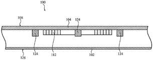
Fig. 1 shows an illustrative front view of one example of an electronic device 100 that includes at least one inductive coil 112. In the illustrated embodiment, the first electronic device 100 is implemented as a portable electronic device, in particular, as a mobile phone. As discussed herein, other embodiments may implement the first electronic device 100 differently, such as, for example, as a laptop or desktop computer, a tablet computing device, a gaming device, a display, a digital music player, a wearable computing device or display, a health monitoring device, and so forth.
The first electronic device 100 includes a housing 102 that at least partially surrounds a display 104, and one or more buttons 106 or other user input devices formed or positioned on a front surface 108 of the first electronic device 100. In some embodiments, device 100 includes a plurality of user input devices, including buttons 106 and a touch-sensitive display screen. The user input device may be used to provide user input to an operating system or other software executing on device 100. The user input device may be operatively coupled to a battery or other power source.
In some embodiments, device 100 may also include one or more audio components, including, for example, a microphone and/or a speaker. One or more audio components may be configured to generate audio output and/or receive audio input. In some embodiments, a speaker may be disposed or positioned within the housing 102 and electrically coupled to the battery 120 (shown in fig. 2). Similarly, a microphone may be disposed or positioned within the housing 102 and electrically coupled to the battery 120.
The housing 102 may form an exterior surface or a portion of an exterior surface and a protective casing for the internal components of the first electronic device 100 and may at least partially surround the display 104. In some cases, the housing 102 defines an opening within which the display 104 is positioned or disposed. The housing 102 may be formed from one or more components, such as a front piece and a back piece, that are operably connected together. Alternatively, the housing 102 may be formed from a single piece that is connected to the display 104 or coupled with the display 104. Additionally, the housing 102 may be formed from a variety of materials, including but not limited to: plastic, glass, sapphire, metal, and/or combinations of multiple materials. The housing 102 may also include a frame 110 or bezel portion that substantially surrounds and/or outlines the display 104. The frame 110 of the housing 102 may indicate the interactive portion of the display 104 and may be opaque to hide internal components of the first electronic device 100.
The display 104 may be implemented using any suitable technology, including but not limited to Liquid Crystal Display (LCD) technology, Light Emitting Diode (LED) technology, Organic Light Emitting Display (OLED) technology, Organic Electroluminescence (OEL) technology, or another type of display technology. In some embodiments, a multi-touch sensing touch screen or touch sensor may be integrated with the display 104. For example, a touch screen or touch sensor may be positioned over the display 104 or integrated with the display 104. In a non-limiting example, a substantially transparent cover or plate can be positioned over the display 104 and/or the touch screen or touch sensor. In some embodiments, the cover may protect the display 104 from contamination without significantly obstructing the view of the user and/or significantly limiting the ability to interact with the touch screen or touch sensor of the first electronic device 100.
The button 106 may be configured to act as a user input device for the first electronic device 100. In some cases, button 106 may include an actuation component in electronic and/or mechanical communication with internal components of first electronic device 100 to provide user input and/or allow a user to interact with various functions of first electronic device 100. In some embodiments, the button 106 may be configured as a single button member surrounded by a portion of the frame 110 of the housing 102. As shown in fig. 1, the buttons may be positioned relative to an outer surface of the first electronic device 100.
As shown in fig. 1 and 2, the first electronic device 100 may also include at least one induction coil 112 positioned or disposed within the housing 102. In particular, as shown in fig. 1 and 2, the first electronic device 100 may include a single inductive coil 112 positioned substantially centrally within the first electronic device 100 and within the housing 102 such that the inductive coil 112 is not exposed. The induction coil 112 may also be positioned below or underneath the display 104 of the first electronic device 100. As shown in fig. 1, and as described herein, the induction coil 112 may be positioned within the housing 102 and may be in electrical communication with an external induction coil of an external electronic device through the display 104 and/or the front surface 108 of the first electronic device 100. Further, as described herein, the inductive coil 112 may be configured as a bi-directional coil, a transmission coil for transmitting power from the first electronic device 100, and a reception coil for receiving or obtaining power for the first electronic device 100. The dashed circle representing the induction coil 112 in fig. 1 may merely be an example location of the induction coil 112 within the first electronic device 100. The position of the induction coil 112 may vary within the housing 102, and in some cases, multiple induction coils 112 may be located within the housing 102. As shown in fig. 1 and described in more detail below with respect to fig. 2, a plurality of alignment magnets 124 may also be positioned within the housing 102.
Fig. 2 illustrates a front view of the first electronic device 100 with the display (item 104 of fig. 1) omitted to expose an interior cavity of the housing 102 (shown in fig. 1). In the non-limiting example shown in fig. 2, the induction coil 112 may be formed of a conductor, such as a wire, that may be concentrically wound to form a set of loops or a spiral shape. The conductive lines may be positioned or formed on an electrical substrate 118 (e.g., a circuit board), and the electrical substrate 118 may be used to electrically couple and/or connect the inductive coil 112 to various other components of the first electronic device 100. The conductive wires forming the induction coil 112 may be formed of various conductive materials, such as metals. However, it should be understood that the inductive coil 112 of the first electronic device 100 may be formed of any suitable material and may be configured in a variety of geometries to allow power to be transferred to or from the first electronic device 100, as described herein.
The first electronic device 100 may also include a battery 120 positioned within the housing 102. In some embodiments, battery 120 may be operatively coupled to components of first electronic device 100 to provide power. In some embodiments, the battery 120 is operatively coupled to the display (item 104 of fig. 1) and/or the controller 122 of the first electronic device 100. Battery 120 may also be operatively coupled to a user input device, microphone, speaker, controller, or other component or subsystem of first electronic device 100. As shown in fig. 2, the battery 120 may be positioned within the housing 102 and may be in electrical communication with the inductive coil 112 of the first electronic device 100 or otherwise operatively coupled to the inductive coil 112. As described herein, the inductive coil 112 may be in electrical communication with the battery 120 to transfer power to or from the battery 120 to increase the charge of the battery 120 or decrease the charge of the battery 120 in order to increase the charge in an external battery of an external electronic device in communication with the first electronic device 100. The battery 120 may be used to power various components or systems of the first electronic device 100.
As shown in fig. 2, the controller 122 may also be positioned within the housing 102 of the first electronic device 100. The controller 122 may be in electrical communication with the inductive coil 112 of the first electronic device 100 to control the operating mode of the inductive coil 112. That is, the controller 122 may be in electrical communication with the inductive coil 112 to adjust the operating mode between a power receiving mode or a power transmitting mode. When the inductive coil 112 is adjusted to the power receiving mode, the inductive coil 112 may be configured as a receiving coil and may receive power to increase the charge of the battery 120. In the power transfer mode, inductive coil 112 may be configured as a transfer coil and may transfer power from first electronic device 100, which may reduce the charge of battery 120 and/or draw power from an external source, such as a wall outlet.
As also shown in fig. 2, the controller 122 may be coupled to the battery 120 or in electrical communication with the battery 120 to monitor the charge of the battery 120. Although not shown, the controller 122 may be in electrical communication with various internal components of the first electronic device 100. In a non-limiting example, the controller 122 may be coupled to a larger computing or processing system that may control the functionality of the first electronic device 100. In another non-limiting embodiment, controller 122 may be integrated with and/or may be configured as part of a larger computing or processing system of first electronic device 100. The controller 122 may be formed by any suitable electronic component, such as a microcontroller or microprocessor, that may be configured to adjust the operating mode of the induction coil 112 and/or may monitor the charge of the battery 120.
As shown in fig. 2, the first electronic device 100 may also include at least one alignment magnet 124 positioned adjacent to the induction coil 112. As shown in fig. 1 and 2, the first electronic device 100 may include a set of alignment magnets 124 positioned adjacent to the induction coil 112 of the first electronic device 100. Two alignment magnets 124 may be positioned on opposite sides or ends of the induction coil 112. Additionally, the alignment magnet 124 may be positioned within the center of the induction coil 112 such that the conductive wire of the induction coil 112 substantially surrounds the alignment magnet 124 of the first electronic device 100. The attractive force between the alignment magnet 124 of the first electronic device 100 and the magnet of the external device may be used to align the induction coil 112 with an external induction coil of the external electronic device, which may facilitate power transfer between the induction coil 112 and the external induction coil. Alignment magnet 124 may be formed from any suitable material having magnetic or electromagnetic properties.
Fig. 3 shows a rear view of the first electronic device 100. The first electronic device 100 may have a camera 126 positioned on the back surface 128. That is, the camera 126 may be positioned on the back surface 128 (opposite the front surface 108 having the display 104 of the first electronic device 100, as shown in FIG. 1). Camera 126 may include any suitable camera device and/or system that may take pictures and/or video with first electronic device 100.
As shown in fig. 3 and as described herein with respect to fig. 1, the induction coil 112 may be positioned within the housing 102. As described herein, the induction coil 112 may be in electrical communication with an external induction coil of an external electronic device through the back surface 128 of the first electronic device 100. For example, the inductive coil 112 located within the housing 102 may be configured to wirelessly inductively couple with an external electronic device through the back surface 128 of the electronic device. As shown in fig. 3, one or more alignment magnets 124 may also be disposed relative to the back surface 128 of the first electronic device 100.
Fig. 4A-4C show cross-sectional side views of the first electronic device 100 including the induction coil 112. The induction coil 112 and the alignment magnet 124 may be positioned at various locations within the housing 102 of the first electronic device 100. In the non-limiting embodiment shown in fig. 4A, the inductive coil 112 and the alignment magnet 124 may be directly coupled to the display 104 of the first electronic device 100, adjacent to the front surface 108. When positioned adjacent to the front surface 108 and/or coupled to the display 104, the inductive coil 112 may provide increased power transfer to an external inductive coil in an external electronic device when the front surface 108 is positioned directly adjacent to the external inductive coil, as described herein. However, it should be understood that the inductive coil 112 coupled to the display 104 may still transfer power through the back surface 128 of the first electronic device 100.
In another non-limiting embodiment shown in fig. 4B, the inductive coil 112 and the alignment magnet 124 may be directly coupled to the housing 102 of the first electronic device 100. As shown in fig. 4B, the induction coil 112 and the alignment magnet 124 may be coupled to the housing 102 adjacent the back surface 128 and opposite the display 104 and/or the front surface 108. The induction coil 112 positioned adjacent to the back surface 128 may transmit power through the display 104 of the first electronic device 100. However, the induction coil 112 may transfer an increased amount of power through the back surface 128 when compared to transferring power through the display 104 and/or the front surface 108.
In an additional non-limiting embodiment shown in fig. 4C, the induction coil 112 and the alignment magnet 124 may be positioned between and offset from the front surface 108 and the back surface 128. In some embodiments, the induction coil 112 and the alignment magnet 124 may be positioned on or relative to an external structure, such as the middle plate 131 shown in fig. 4C. In some cases, the induction coil 112 and the alignment magnet 124 may be positioned between the front surface 108 and the back surface 128 such that power transfer to and/or from the induction coil 112 may be substantially equal through the front surface 108 and the back surface 128.
The example of fig. 4A-4C show the alignment magnet 124 and the induction coil 112 substantially aligned or in one plane. However, it should be understood that the alignment magnet 124 may be positioned within a portion of the housing 102 that is different or non-coplanar with respect to the induction coil 112. In a non-limiting example not shown, the induction coil 112 may be directly adjacent to the front surface 108 and/or the display 104, and the alignment magnet 124 may be directly adjacent to the back surface 128. In a non-limiting embodiment, and as described herein, the alignment magnet 124 may facilitate alignment of the induction coil 112 and an external induction coil of an external electronic device to provide optimal power transfer between the first electronic device 100 and the external electronic device.
Fig. 5A and 5B show front and rear views, respectively, of a second electronic device 200 comprising induction coils 212a,212B,212 c. In the non-limiting example embodiment shown in fig. 5A and 5B, the second electronic device 200 may be formed as a tablet computing device. The second electronic device 200 may include substantially similar components to the first electronic device 100, such as a housing 202, a display 204, a camera 226, buttons 206, and other user input devices. The second electronic device 200 may include audio elements such as a speaker and/or a microphone. It should be appreciated that similarly numbered and/or named components may operate in a substantially similar manner. Redundant description of these components has been omitted for clarity.
The second electronic device 200 may include a set of inductive coils 212a,212b,212c positioned or disposed within the housing 202. As shown in fig. 5A and 5B, the set of inductive coils 212a,212B, and 212c can be positioned within the entire housing 202. In a non-limiting example, each inductive coil of the set of inductive coils 212a,212b, and 212c can be positioned within the boundaries of the display 204 and/or within the frame 210 of the electronic device 200. Further, in a non-limiting example, as shown in fig. 5A and 5B, the set of induction coils 212a,212B, and 212c can be evenly distributed and positioned substantially in the center of the second electronic device 200, and the induction coil 212B can be positioned between the induction coils 212a,212 c.
As shown in fig. 5A, the second electronic device 200 may also include a set of alignment magnets 224 positioned adjacent to each of the set of inductive coils 212a,212b,212 c. Similar to fig. 1-3, the induction coils 212a,212c may have two alignment magnets 224 positioned on opposite sides of the induction coils 212a,212c, and an alignment magnet 224 positioned within the induction coils 212a,212c and/or surrounded by the induction coils 212a,212 c. As shown in fig. 5A, the alignment magnets 224 in the second electronic device 200 may be positioned on opposite sides of the induction coils 212a,212 c.
In a non-limiting example, the induction coil 212b may include four different alignment magnets 224. As shown in fig. 5A, four different alignment magnets 224 may surround the induction coil 212b substantially on four sides. As described herein, the inclusion of four different alignment magnets 224 in the second electronic device 200 may allow an external electronic device to be coupled to the second electronic device 200 and/or the alignment magnets 224 in multiple orientations or positions.
Fig. 6A and 6B show top and bottom views, respectively, of a third electronic device 300. The third electronic device 300 may be a portable or wearable electronic device 300 (hereinafter "third electronic device") that includes a health monitoring device. The third electronic device 300 as shown in fig. 6A and 6B may be configured to provide health-related information or data, such as, but not limited to, heart rate data, blood pressure data, temperature data, oxygen content data, diet/nutrition information, medical reminders, health-related reminders or information, or other health-related data. The third electronic device 300 may optionally communicate health-related information to a separate electronic device, such as a tablet computing device, a telephone, a personal digital assistant, a computer, or the like. Additionally or alternatively, the third electronic device 300 may provide additional information such as, but not limited to, time, data, health, status, or externally connected or communicating devices, and/or software executing on such devices; a message; video; operation commands, etc. (and any of the above may be received from an external device other than other communications).
The third electronic device 300 may include a housing 302 at least partially surrounding a display 304 and one or more buttons 306, crowns 308, or input devices. The housing 302 may form an exterior surface or a portion of an exterior surface and a protective casing for the internal components of the third electronic device 300 and may at least partially surround the display 304. The housing 302 may include an opening in which the display 304 is positioned or disposed. The housing 302 may be formed from one or more components, such as a front piece and a back piece, that are operably connected together. Alternatively, the housing 302 may be formed from a single piece that is connected to the display 304 or coupled with the display 304. The housing 302 may be formed from one or more materials, including but not limited to: plastic, glass, sapphire, metal, and/or other various materials or combinations of materials.
The third electronic device 300 may also have a wearable band 310 (partially shown in fig. 6A and 6B) coupled to the housing 302. The wearable band 310 may be used to secure the third electronic device 300 to a user, or any other object capable of receiving the electronic device 300. In a non-limiting example where the third electronic device 300 is a watch, the wearable band 310 may secure the watch to the user's wrist. In other non-limiting examples, the third electronic device 300 may secure the watch to or within another part of the user's body.
The display 304 may be implemented using any suitable technology, including but not limited to Liquid Crystal Display (LCD) technology, Light Emitting Diode (LED) technology, Organic Light Emitting Display (OLED) technology, Organic Electroluminescence (OEL) technology, or another type of display technology. In some embodiments, display 304 may also include a multi-touch sensing touch screen and/or touch sensors configured to receive touch input from a user. In some embodiments, a touch screen or touch sensor is integrated with the display 304, and may be disposed above the display 304 or integrated with the display 304, for example.
The third electronic device 300 also includes one or more user input devices, including buttons 306, a crown 308, and/or a touch sensor disposed or positioned relative to an exterior surface of the third electronic device 300. In some cases, button 306 and/or crown 308 may include actuation components in electronic and/or mechanical communication with internal components of third electronic device 300 to provide user input and/or allow a user to interact with various functions of third electronic device 300. The button 306 may similarly include a sensor, such as a biometric sensor, a touch sensor, or the like. Crown 308 may be a rotatable and/or actuatable input device for interacting with third electronic device 300. The third electronic device 300 may also include other forms of user I/O, including audio elements, such as a speaker and/or a microphone.
As shown in fig. 6A and 6B, the third electronic device 300 may further include an induction coil 312. The third electronic device 300 may include a single inductive coil 312 positioned within the housing 302. As shown in fig. 6A and 6B and described herein, the induction coil 312 may be in electrical communication through the display 304 (see fig. 6A) and/or through the rear charge plate 330 (see fig. 6B) of the third electronic device 300.
The third electronic device 300 may also include a single alignment magnet 324. As shown in fig. 6A and 6B, a single alignment magnet 324 may be positioned within the induction coil 312 of the third electronic device 300 and/or may be substantially surrounded by the induction coil 312. Due to the size of the third electronic device 300, only a single alignment magnet 324 may be included within the electronic device 300. However, it should be understood that the third electronic device 300 may include a set of alignment magnets 324.
Fig. 7A shows a top view of the fourth electronic device 400. In the non-limiting example embodiment shown in fig. 7A, the fourth electronic device 400 may be formed as a portable computing device, such as a laptop computer. The fourth electronic device 400 may have an outer or top case 440 for housing and/or protecting the internal components of the fourth electronic device 400. The fourth electronic device 400 may also have a set of keys 442 that protrude through the top case 440 forming a keyboard user input device. The set of keys 442 may be used to allow a user to interact with the fourth electronic device 400. The trackpad 444 may also be positioned within the top case 440 of the fourth electronic device 400. Trackpad 444 may be positioned adjacent to the set of keys 442 of fourth electronic device 400. Trackpad 444, like the set of keys 442, may allow a user to interact with fourth electronic device 400. The fourth electronic device 400 may also include other components for performing user I/O, including audio elements, such as a speaker and/or a microphone.
The fourth electronic device 400 may also include a display 404 and a display housing 446. The display housing 446 may form an outer and/or protective enclosure for the display 404 of the fourth electronic device 400. The display 404 may provide visual output to a user of the fourth electronic device 400.
The fourth electronic device 400 may also include a set of inductive coils 412a,412b,412c positioned within the top case 440. As shown in fig. 7A, the set of inductive coils 412a,412b,412c may be evenly distributed within the top case 440 with the set of keys 442. The induction coils 412a,412c may be positioned on either side of the trackpad 444, and the induction coil 412b may be positioned below and/or aligned with the trackpad 444. As described herein, each induction coil of the set of induction coils 412a,412b, and 412c may be in electrical communication with an external induction coil of an external electronic device through the top case 440.
Fig. 7B shows a top view of the fourth electronic device 400 in a closed configuration. In the closed configuration, the display housing 446 may be coupled to the top case 440 of the fourth electronic device 400 and may substantially cover the set of keys 442. As shown in fig. 7B, the display housing 446 may also include a set of induction coils 412. The inductive coil 412 positioned within the display housing 446 may be positioned between the display 404 (see fig. 7A) and an outer surface of the display housing 446. The set of inductive coils 412 positioned within the display enclosure 446 may be evenly distributed throughout the display enclosure 446. As similarly described herein, each inductive coil of the set of inductive coils 412 within the display housing 446 may be in electrical communication with an external inductive coil of an external electronic device through the display housing 446, as described herein.
The fourth electronic device 400 may or may not include an alignment magnet. In the non-limiting embodiment shown in fig. 7A and 7B, the fourth electronic device 400 does not include an alignment magnet. In other non-limiting examples not currently shown, each of the induction coils 412 of the fourth electronic device 400 may include at least one alignment magnet. As described herein, an alignment magnet that may be formed within the fourth electronic device 400 may be used to align an external inductive coil of an external electronic device with the inductive coil 412 of the fourth electronic device 400.
Fig. 8 shows a front view of a fifth electronic device 500. The fifth electronic device 500 may be a protective case or cover for a mobile phone or other portable electronic device. The fifth electronic device 500 may be configured to at least partially surround a housing of the portable electronic device and provide additional protection from physical shock, frictional contact, exposure to water, and/or other possible damaging events. Thus, the fifth electronic device 500 generally functions as an accessory and is paired with another, separate portable electronic device to provide protection.
The fifth electronic device 500 may include a housing 502 configured to at least partially surround another, separate portable electronic device. The housing 502 may form an exterior surface or portion of an exterior surface and a protective case for the internal components of the fifth electronic device 500 as well as a stand-alone portable device mounted or positioned within the fifth electronic device 500. The housing 502 may include one or more coupling features 504 configured to engage with a stand-alone portable device mounted or positioned within the fifth electronic device 500. The coupling feature 504 may include a spring-loaded or compliant clip configured to attach a separate portable device to the fifth electronic device 500. The coupling features 504 may also provide for alignment or fixed positioning of the two devices relative to each other.
The housing 502 may be formed from one or more components, such as a front piece and a back piece, that are operably connected together. One or more components of the housing 502 may form a cavity or recess in which the internal components are positioned. The fifth electronic device 500 may be formed from materials and components particularly suited for resisting a drop event when another portable electronic device, such as a mobile phone, is installed or inserted into the fifth electronic device 500. The housing 502 may be formed from a group of different materials including, but not limited to: plastic, elastomer, carbon composite, metal, and/or other various materials or combinations of materials.
The fifth electronic device 500 may also include one or more user input devices, including buttons, keys, or touch sensors disposed or positioned relative to an exterior surface of the housing 502. The fifth electronic device 500 may also include one or more mechanical actuators configured to translate user input to an actuator or user input device located on a separate electronic device mounted or held within the fifth electronic device 500. In some alternative embodiments, the fifth electronic device 500 includes a keyboard or other user input device similar to the set of keys 442 of the keyboard of the fourth electronic device 400 shown in fig. 7A.
As shown in fig. 8, the fifth electronic device 500 may further include an induction coil 512 configured to transmit and/or receive wireless power to/from another device. An induction coil 512 is positioned within the housing 502 and may be operatively coupled to an internal battery and/or other electronic circuitry. The inductive coil 512 may be in electrical communication (e.g., wirelessly coupled) through a surface 528 of the fifth electronic device 500.
Although not shown in fig. 5A-8, it should be understood that each of the electronic devices 200,300,400,500 may include a controller and a battery, similar to that described herein with respect to the first electronic device 100 in fig. 2. That is, the second electronic device 200, the third electronic device 300, the fourth electronic device 400, and the fifth electronic device 500 may further include a controller for adjusting an operation mode of one or more induction coils in the electronic device, and a battery for supplying power to the electronic device.
Fig. 9A-21 illustrate various embodiments of at least two electronic devices in electrical communication for transferring power between the electronic devices and/or inductively charging one electronic device by another electronic device. In the following examples, reference will be made to two (or more) induction coils aligned or substantially aligned with each other. In some cases, only a single contour or shape may be shown in the corresponding figures, which may represent two (or more) induction coils. In these cases, multiple item numbers may refer to the same profile or shape, but it should be understood that there may actually be two (or more) induction coils at the same alignment position, but positioned in different planes of their corresponding devices. A plurality of concentric or overlapping shapes that may correspond to individual induction coils are omitted for clarity.
Fig. 9A and 9B illustrate a first electronic device 100 and a fifth electronic device 500 that may be coupled to wirelessly exchange power with each other using a pair of inductive coils. In the example of fig. 9A and 9B, the fifth electronic device 500 may form a protective cover or case for a stand-alone portable device, such as the first electronic device 100. Fig. 9A shows the first electronic device 100 mounted or positioned within a fifth electronic device 500. In some implementations, the first electronic device 100 may be installed by pressing the first electronic device 100 into the coupling feature 504 of the fifth electronic device 500. The coupling features 504 may secure two devices together and provide alignment between the devices.
Fig. 9B shows a top view of the first electronic device 100 positioned within the fifth electronic device 500. The first electronic device 100 may be in electrical communication with the fifth electronic device 500. The back surface 128 of the first electronic device 100 (see fig. 3) may be positioned on the surface 528 of the fifth electronic device 500 and/or may contact the surface 528. When positioned on the surface 528 of the fifth electronic device 500, the inductive coil 112 of the first electronic device 100 may be aligned with and/or in electrical communication with the inductive coil 512 of the fifth electronic device 500. When in electrical communication, the respective inductive coil 112,512 may transfer power between the electronic devices 100, 500.
To transfer power between the electronic devices 100,500, the operating modes of the electrically communicated inductive coils 112,512 may be different from each other. In a non-limiting example, as shown in fig. 9B, electronic device 500 may transmit power to electronic device 100. In a non-limiting example, the inductive coil 112 of the electronic device 100 may be in a power receiving mode and may act as a receiving coil. Further, the inductive coil 512 of the electronic device 500 is in electrical communication with the inductive coil 112, can be in a power transfer mode, and can act as a transmission coil. Upon electrical communication via the inductive coils 112,512, the fifth electronic device 500 may provide power to the first electronic device 100. Since the power is supplied from the fifth electronic device 500 to the first electronic device 100, the charge of the battery 120 of the first electronic device 100 (see, for example, fig. 2) may be increased, and the charge of the battery of the fifth electronic device 500 (not shown) may be decreased. The power supplied to the first electronic device 100 in order to charge the battery 120 may be supplied from the battery of the fifth electronic device 500.
In another non-limiting embodiment, as shown in FIG. 10, a first electronic device 100 may be in electrical communication with a second electronic device 200. The back surface 128 (see fig. 3) of the first electronic device 100 may be positioned on the front surface 208 of the second electronic device 200 and/or may contact the front surface 208. When positioned on the front surface 208 of the second electronic device 200, the inductive coil 112 of the first electronic device 100 may be aligned with and/or in electrical communication with the inductive coil 212b of the second electronic device 200. Upon electrical communication, the respective inductive coil 112,212b may transfer power between the electronic devices 100, 200.
To transfer power between the electronic devices 100,200, the operating modes of the electrically communicated inductive coils 112,212b may be different from each other. In a non-limiting example, as shown in fig. 10, electronic device 200 may transmit power to electronic device 100. In a non-limiting example, the inductive coil 112 of the electronic device 100 may be in a power receiving mode and may act as a receiving coil. Further, the inductive coil 212b of the electronic device 200 is in electrical communication with the inductive coil 112, may be in a power transfer mode, and may act as a transfer coil. Once in electrical communication via the inductive coils 112,212b, the second electronic device 200 may provide power to the first electronic device 100. As power is supplied from the second electronic device 200 to the first electronic device 100, the charge of the battery 120 of the first electronic device 100 (see, for example, fig. 2) may be increased, and the charge of the battery of the second electronic device 200 (not shown) may be decreased. The power provided to the first electronic device 100 in order to charge the battery 120 may be provided from a battery of the second electronic device 200.
The respective induction coils 112,212b may be aligned using alignment magnets 124,224 prior to transferring power between the electronic devices 100, 200. As shown in fig. 11, the alignment magnet 124 of the first electronic device 100 may be magnetically attracted to and/or may be magnetically coupled to an alignment magnet 224 positioned adjacent to the inductive coil 212b of the second electronic device 200. The magnetic coupling of the alignment magnets 124,224 of the respective electronic devices 100,200 may provide a desired coupling and/or alignment for the induction coils 112,212b when transferring power.
Fig. 12 illustrates another non-limiting example of two electronic devices in electrical communication for transferring power or data between the electronic devices and/or inductively charging one electronic device with the other electronic device. As shown in fig. 12, the inductive coil 112 of the first electronic device 100 may be coupled to the inductive coil 212a of the second electronic device 200. Due to the position of the alignment magnets 124,224 within the induction coil 212a and/or the respective electronic device 100,200 (see fig. 1-3, 5A) coupled to the second electronic device 200, the first electronic device 100 may be laterally oriented relative to the second electronic device 200 when the induction coil 112 is in electrical communication with the induction coil 212 a. That is, the position of the alignment magnet 124,224 within the respective electronic device 100,200 may determine the orientation of the first electronic device 100 when positioned on or touching the second electronic device 200. By positioning the first electronic device 100 on the second electronic device 200 such that the inductive coils 112 and 212a are in electrical communication, a substantial portion of the display 204 of the second electronic device 200 remains visible and/or interacted with by the user, as described herein.
In a non-limiting example as shown in fig. 12, a first electronic device 100 may transmit power to a second electronic device 200. The inductive coil 112 of the electronic device 100 may be in a power transfer mode and may act as a transfer coil. Further, the inductive coil 212a of the second electronic device 200 in electrical communication with the inductive coil 112 may be in a power receiving mode and may act as a receiving coil. Once in electrical communication via the inductive coils 112,212a, the first electronic device 100 may provide power to the second electronic device 200. Since power is supplied from the first electronic device 100 to the second electronic device 200, the charge of the battery 120 of the first electronic device 100 (see fig. 2) may be decreased, and the charge of the battery of the second electronic device 200 (not shown) may be increased. The power supplied to the second electronic device 200 in order to charge the battery 200 of the second electronic device 200 may be supplied from the battery of the first electronic device 100.
FIG. 13 shows another non-limiting exemplary embodiment. As shown in fig. 13, a plurality of electronic devices may be positioned on the second electronic device 200 and/or in contact with the second electronic device 200. As shown in fig. 13, the first electronic device 100 and the third electronic device 300 may be positioned on the second electronic device 200 or adjacent to the second electronic device 200. The first electronic device 100 and the third electronic device 300 may be positioned on the back surface 228 of the second electronic device 200. As shown in fig. 13, the first electronic device 100 may be positioned substantially in the center of the second electronic device 200 such that the inductive coil 112 of the first electronic device 100 is in electrical communication with the inductive coil 212b of the second electronic device 200.
Further, as shown in fig. 13, a third electronic device 300 may be positioned on the second electronic device 200 such that the inductive coil 312 of the third electronic device 300 may be in electrical communication with the inductive coil 212a of the second electronic device 200. The inductive coil 312 of the third electronic device 300 may be aligned with the inductive coil 212a of the second electronic device 200 using alignment magnets 224,324, as similarly described herein. However, since the third electronic device 300 has only a single alignment magnet 324 positioned within the induction coil 312 and/or substantially surrounded by the induction coil 312, the induction coil 312,212a may be aligned with only a single respective alignment magnet 224,324 of the respective electronic device 200, 300.
In a non-limiting example, the second electronic device 200 may transmit power to both the first electronic device 100 and the third electronic device 300. As a result, the inductive coils 212a,212b of the second electronic device 200 may transmit power and may act as transmission coils, and the inductive coils 112,312 of the first electronic device 100 and the third electronic device 300, respectively, may receive power and may act as receiving coils.
However, it should be understood that the electronic devices 100,200,300 shown in FIG. 13 may transmit power in a variety of ways through all of the different electronic devices. In an additional non-limiting example, the first electronic device 100 may transmit power to the second electronic device 200, and the second electronic device 200 may transmit power to the third electronic device 300. In an additional non-limiting example, the inductive coils 112,212a of the first and second electronic devices 100,200, respectively, may transmit power and may act as a transmission coil, and the inductive coils 212b,312 of the second and third electronic devices 200,300 may receive power and may act as a reception coil.
Fig. 14 illustrates other non-limiting examples of a plurality of electronic devices configured to inductively charge at least one of the electronic devices. As shown in fig. 14, the third electronic device 300 may be in contact with and/or positioned on the front surface 108 of the first electronic device 100. The first electronic device 100 may be positioned on the front surface 208 of the second electronic device 200 and/or may contact the front surface 208. In the non-limiting example shown in fig. 14, the induction coils 112,212a,312 may all be aligned with and in electrical communication with adjacent induction coils or with each of the aligned induction coils. The inductive coil 312 of the third electronic device 300 may be in electrical communication with the inductive coil 112 of the first electronic device 100. In this example, the induction coil 312 may also be in electrical communication with the induction coil 212a of the second electronic device 200. Further, in a further non-limiting example shown in fig. 14, the inductive coil 112 of the first electronic device 100 may be in electrical communication with both inductive coils 312 and 212 a.
Since electrical communication is established between the first electronic device 100, the second electronic device 200, and the third electronic device 300, power may be transmitted through the electronic devices in any manner. For example, the second electronic device 200 may transmit power to increase the charge of the battery 120 (see fig. 2) of the first electronic device 100 while increasing the charge of the battery (not shown) of the third electronic device 300. In this example, the first electronic device 100 may not only receive power, but may also transmit and/or leak a portion of the received power to the third electronic device 300. As such, the inductive coil 212a of the second electronic device 200 may transmit power and may act as a transmit coil, and the inductive coil 312 of the third electronic device 300 may receive power and may act as a receive coil. The induction coil 112 of the first electronic device 100 may continuously alternate between a transmission coil for transmitting power to the third electronic device 300 and a reception coil for receiving power from the second electronic device 200.
Fig. 15-20 illustrate various non-limiting examples, including a fourth electronic device 400 and one or more external electronic devices in electrical communication for transferring power between the electronic devices and/or for inductively charging one electronic device by another electronic device. As shown in fig. 15, the first electronic device 100 may be positioned on the top case 440 of the fourth electronic device 400 and/or may contact the top case 440. The inductive coil 112 of the first electronic device 100 may be aligned with and in electrical communication with the inductive coil 412a positioned within the top case 440 of the fourth electronic device 400. As described herein, the inductive coil 112,412a may be in electrical communication to charge a battery of the respective electronic device 100, 400.
Fig. 16 illustrates another non-limiting example in which the first electronic device 100 may be positioned on and/or may contact a trackpad 444 formed in the top case 440 of the fourth electronic device 400. The inductive coil 112 of the first electronic device 100 may be aligned with and in electrical communication with the inductive coil 412b positioned below the trackpad 444 of the fourth electronic device 400. As described herein, the inductive coils 112,412b may be in electrical communication to charge a battery of the respective electronic device 100, 400. Further, in the non-limiting example shown in FIG. 16, since the first electronic device 100 substantially covers the trackpad 444 of the fourth electronic device 400, a touch screen or touch sensor of the display 104 may be used as an alternative input to the trackpad 444. In some embodiments, the first electronic device 100 and the fourth electronic device 400 may not only supply power, but may also transmit data such that a touch screen or touch sensor of the display 104 may receive touch input as a replacement for the trackpad 444 of the fourth electronic device 400 (when the induction coil 112 is in electrical communication with the induction coil 412 b). By configuring the display 104 of the first electronic device 100 to act as the trackpad 444, the first electronic device 100 and the fourth electronic device 400 can be in electrical communication to inductively charge the battery of one of the respective devices while also allowing a user to interact with the fourth electronic device 400 via the display 104 using the trackpad 444 functionality.
FIG. 17 shows an additional non-limiting example of a plurality of electronic devices. As shown in fig. 17, the first electronic device 100 may be positioned on the top case 440 of the fourth electronic device 400 and/or may contact the top case 440. The inductive coil 112 of the first electronic device 100 may be aligned with and in electrical communication with the inductive coil 412a positioned within the top case 440 of the fourth electronic device 400. In addition, the third electronic device 300 may be positioned on the top case 440 and contact the top case 440, opposite to the first electronic device 100. As shown in fig. 17, the inductive coil 312 of the third electronic device 300 may be aligned with and in electrical communication with the inductive coil 412c positioned within the top case 440 of the fourth electronic device 400. As described herein, the induction coils 112,312,412a,412c may be in electrical communication to charge a battery of the respective electronic device 100,300, 400.
Fig. 18 shows a plurality of electronic devices 100,300 positioned on the display housing 446 of the fourth electronic device 400 and/or contacting the display housing 446. The electronic devices 100,300 may be spaced apart and positioned on the display housing 446 of the fourth electronic device 400. As shown in fig. 18, the induction coil 112 of the first electronic device 100 may be in electrical communication with an induction coil 412 positioned within the display housing 446. Further, the inductive coil 312 of the third electronic device 300 may be in electrical communication with an external inductive coil 412 positioned within the display housing 446 of the fourth electronic device 400.
Fig. 19 and 20 show further non-limiting example embodiments of a plurality of electronic devices 100,200,300 positioned on and/or contacting the display housing 446 of the fourth electronic device 400. As shown in fig. 19, the first electronic device 100 may be positioned on the fourth electronic device 400 and/or may contact the fourth electronic device 400, and the third electronic device 300 may be positioned on the first electronic device 100 and/or may contact the first electronic device 100. As similarly described herein, the induction coil 112,312,412 may be aligned and in electrical communication for transferring power through at least one of the electronic devices 100,300, 400. Further, as shown in fig. 19, the second electronic device 200 may be positioned on the display housing 446 of the fourth electronic device 400 and/or may contact the display housing 446 adjacent to the first electronic device 100 and/or the third electronic device 300. The inductive coil 212a or 212c of the second electronic device 200 may be aligned with and in electrical communication with an external inductive coil 412 positioned within the display housing 446 of the fourth electronic device 400.
FIG. 20 shows electronic devices 100,200,300,400 stacked on top of each other. As such, the inductive coil 312 of the third electronic device 300, the inductive coil 112 of the first electronic device 100, the inductive coil 212b of the second electronic device 200, and the inductive coil 412 positioned in the display housing 446 of the fourth electronic device 400 may be substantially aligned with and in electrical communication with adjacent inductive coils and/or all aligned inductive coils. As similarly described herein, each of the inductive coils 112,212b,312, and 412 may be configured to transmit and/or receive power from an external electronic device.
As also shown in fig. 20, fourth electronic device 400 may be electrically connected to cable 448 to charge fourth electronic device 400. Cable 448 may be electrically connected to fourth electronic device 400 to increase the charge of a battery (not shown) of fourth electronic device 400. In the non-limiting example shown in fig. 20, cable 448 may increase the charge of the battery of fourth electronic device 400 when fourth electronic device 400 charges the electronic device battery of at least one of first electronic device 100, second electronic device 200, and third electronic device 300. As long as fourth electronic device 400 receives more power from cable 448 than it transmits to one or more external electronic devices 100,200,300, fourth electronic device 400 may increase the charge of its battery while increasing the charge of the battery in first electronic device 100, second electronic device 200, and/or third electronic device 300.
Fig. 21 shows a front view of a sixth electronic device 600. In the non-limiting example embodiment shown in fig. 21, the sixth electronic device 600 may be formed as a smartphone substantially similar to the first electronic device 100 described herein. As shown in fig. 21, the sixth electronic device 600 comprises a pair of (concentric) induction coils 650,652, which are described in more detail below with respect to fig. 22A-22B. The sixth electronic device 600 may also include one or more alignment magnets 624. It should be appreciated that similarly numbered and/or named components may operate in a substantially similar manner. Redundant description of these components has been omitted for clarity.
In some embodiments, sixth electronic device 600 may include first inductive coil 650 and second inductive coil 652. First induction coil 650 and second induction coil 652 may be positioned concentric to each other. In some embodiments, first (outer) inductive coil 650 may substantially encompass second (inner) inductive coil 652 and/or be positioned concentrically about second (inner) inductive coil 652. First induction coil 650 may be spaced a distance from second induction coil 652 to minimize and/or eliminate electrical interference and/or noise when one or both of first induction coil 650 and second induction coil 652 are transmitting power. First induction coil 650 and second induction coil 652 may be formed from substantially similar materials as described with respect to induction coil 112 of fig. 2.
Fig. 22A and 22B show simplified schematic diagrams of a first (inner) induction coil 650 and a second (outer) induction coil 652 in electrical communication with one or more external induction coils. In some cases, one or more outer inductive coils 652 may be activated to optimize or improve wireless power transfer efficiency between coil sets. As shown in fig. 22A, first inductive coil 650 and second inductive coil 652 may be in electrical communication or wirelessly coupled with a single external inductive coil, such as inductive coil 112 of first electronic device 100 (see fig. 1-3). Reference lines in fig. 22A indicate how first induction coil 650 may be aligned with induction coil 112 when first induction coil 650 is in electrical communication with induction coil 112. Further, the reference line represents how second induction coil 652 may be aligned with induction coil 112 and may have substantially the same dimensions as induction coil 112.
In some embodiments, the coupling efficiency between the pair of inductive coils may be optimal or maximized when the size of the receive coil is less than or equal to the size of the transmit coil. Thus, the configuration shown in fig. 22A may correspond to the case where: together, first inductive coil 650 and second inductive coil 652 act as an inductive receiver, and inductive coil 112 acts as an inductive transmitter. In some implementations, the second (outer) inductive coil 652 can be selectively operated according to a predicted or measured coupling efficiency with an external coil, such as inductive coil 112 shown in fig. 22A. In contrast, the configuration shown in fig. 22A may also correspond to the case where: first inductive coil 650 and second inductive coil 652 together act as an inductive transmitter, and inductive coil 112 acts as an inductive receiver. In some implementations, the second (outer) inductive coil 652 can be selectively operated according to a predicted or measured coupling efficiency with the inductive coil 112.
In general, first inductive coil 650 and second inductive coil 652 may operate substantially similar to the inductive coils described herein. In a non-limiting example, first inductive coil 650 and second inductive coil 652 may function as both a transmission coil in a power transmission mode and a reception coil in a power reception mode. First inductive coil 650 and second inductive coil 652 may both be activated in a transmit mode of operation for transmitting power to inductive coil 112. In some cases, first inductive coil 650 and second inductive coil 652 may operate independently or separately. In a non-limiting example where first inductive coil 650 and second inductive coil 652 operate independently, a controller (not shown) of electronic device 600 may determine or estimate a coupling efficiency between the inductive coils between the devices. For example, the controller may estimate the coupling efficiency by comparing an estimated amount of power transmitted/sourced by one device to an actual or estimated amount of power received by another device. In some cases, the controller may be used to activate or deactivate the second (outer) inductive coil 652 based on the estimated coupling efficiency.
In some cases, the transmission device includes a plurality of outer coils surrounding the first coil. Each outer coil may be activated independently based on the estimated coupling efficiency. This allows a single transmission coil to wirelessly couple power with high efficiency with a wide range of receiving coils that may vary in size. The estimated coupling efficiency may be based on an estimated value of the transmitted and received power. The estimated coupling efficiency may also be based on manufacturing specifications of the device. For example, if a receiving device is identified, the transmitting device may activate one or more outer coils based on the type or size of the receiving coil designated as being in the identified device. Additionally or alternatively, the device 600 may be configured to activate one or more outer coils for two or more transmission modes and estimate the power coupling efficiency for each transmission mode. The transmission mode with the highest estimated coupling efficiency may be selected to wirelessly transmit power between the two devices.
With respect to fig. 22A, each of the first inductive coil 650 and the second inductive coil 652 may be configured as either a transmit coil or a receive coil. In a non-limiting example, as described herein, first inductive coil 650 may operate only as a transmission coil for transmitting power to inductive coil 112, and second inductive coil 652 may operate only as a reception coil for receiving power from inductive coil 112. When the sixth electronic device 600 is in the power receiving mode, the second inductive coil 652 may be operational and the first inductive coil 650 may be disabled. Conversely, when the sixth electronic device 600 is in the power transfer mode, the first inductive coil 650 may be operational and the second inductive coil 652 may be disabled.
FIG. 22B shows another non-limiting example of first and second induction coils 650,652 in electrical communication with external first and second induction coils 660, 662 of an external electronic device (not shown). As shown in fig. 22B, first inductive coil 650 may be aligned with outer first inductive coil 660 and may be substantially similar in size to outer first inductive coil 660. Further, first induction coil 650 may be positioned concentrically around outer second induction coil 662 and/or may surround outer second induction coil 662. As also shown in fig. 22B, second inductive coil 652 may be concentrically surrounded and/or encircled by outer first inductive coil 660, may be aligned with outer second inductive coil 662, and may be substantially similar in size to outer second inductive coil 662.
Similar to fig. 22A, first induction coil 650, second induction coil 652, external first induction coil 660, and external second induction coil 662 may function as both transmission and reception coils, or may function as dedicated transmission or reception coils. Further, the first induction coil 650, the second induction coil 652, the external first induction coil 660, and the external second induction coil 662 may be activated together when power is transferred between the induction coils, or only one induction coil per electronic device may be operated when power is transferred. Further, similar to fig. 22A, the controller of each electronic device may determine which coil combination is likely to be most efficient when transferring power, and may activate a specified combination of induction coils based on the efficiency determination. In one non-limiting example, sixth electronic device 600 may transfer power to an external electronic device (not shown) having external first and second inductive coils 660, 662. Respective controllers in the electronic device may measure or estimate the coupling efficiency, and one or both of the controllers may disable/deactivate or enable/activate one or more of the inductive coils to increase the coupling efficiency. In some cases, one or both of the controllers perform iterative measurements and, given the hardware configuration of the respective device and set of induction coils, activate or deactivate the coils to determine the configuration that provides the greatest efficiency.
When utilizing the inductive charging systems and processes described herein with respect to fig. 1-22B, the display characteristics of the electronic device may be changed or modified based on the inductive charging system. Turning to fig. 23A-23C, a process for aligning a first electronic device 100 with a second electronic device 200 using a display feature is shown. As shown in fig. 23A, the first electronic device 100 and the second electronic device 200 can operate. As a result, the first electronic device 100 may include a set of iterative computerized application icons 160, referred to herein as "application icons," that are visible on the display 104. The set of application icons 160 may be arranged in rows and columns on the display 104 of the first electronic device 100. As shown in fig. 23A, the second electronic device 200 may also include a set of application icons 260 visible on the display 204. The application icons 160,260 are provided by way of non-limiting example only, and other graphical objects or elements may be displayed and altered or manipulated in a manner similar to that described herein.
In some embodiments, the inductive coils 112,212a-212c are used to detect the presence or proximity of two devices 100, 200. In some cases, the inductive coil 112 of the first electronic device 100 may be briefly coupled and/or in electrical communication with the inductive coils 212a-212c of the second electronic device 200 as the first electronic device 100 moves in the direction (D) over the device 200. In a non-limiting example, as shown in fig. 23A and 23B, upon brief coupling and/or communication between the inductive coils 112a-112c of the first electronic device 100 and the inductive coils 212a-212c of the second electronic device 200, the presence or proximity of the devices is detected and one or both of the electronic devices 100,200 may enter an inductive charging mode. In some embodiments, a proximity sensor or other sensing device is used to detect the presence or proximity of the electronic device 100,200, and may be used to trigger an inductive charging mode in one or both of the electronic devices 100, 200.
In some embodiments, the graphical output of one or both of the displays of the electronic devices 100,200 may be changed or modified in response to the coupling between the inductive coils 112,212a-212 c. FIG. 23B illustrates first electronic device 100 and second electronic device 200 aligned according to an inductive charging mode after first electronic device 100 is moved over and coupled and/or in communication with second electronic device 200 via inductive coils 112,212a-212 c. As shown in FIG. 23B, the display of the electronic device 100,200 may be modified such that the application icons 160,260 (see FIG. 23A) may no longer be displayed or visible on one or both of the first electronic device 100 and the second electronic device 200. In the non-limiting example shown in FIG. 23B, first electronic device 100 and second electronic device 200 may include device charging graphical representations that are visible on displays 104,204 in response to coupling and/or communication between inductive coils 112,212a-212c, respectively. For example, an induction coil graphic 162 may be presented on the display 104 of the first electronic device 100 for indicating the location of the induction coil 112 within the housing 102 of the first electronic device 100.
In some implementations, one or both of the displays 104,204 can present a graphical output in response to the first electronic device 100 being proximate to the second electronic device 200. In some cases, the graphical output may include or indicate an alignment condition between the electronic devices 100,200, which may be used to assist or guide alignment between the two electronic devices 100, 200. For example, as shown in FIG. 23B, the display 104 may also present an indicator box 164 that may provide a visual indicator to the user of the alignment between the electronic devices 100, 200. In some cases, indicator box 164 may include text or graphics that may relate to the alignment of first electronic device 100 and second electronic device 200 when attempting to align induction coils 112,212b to facilitate efficient power transfer between electronic devices 100,200, as described herein. In the example embodiment shown in fig. 23B, the indicator block 164 may present a graphic to the user indicating that the first electronic device 100 is not properly aligned with the second electronic device 200 and, therefore, that optimal inductive charging cannot be achieved between the electronic devices 100, 200. In some cases, the indicator block 164 may indicate the degree of misalignment, or provide visual guidance to assist the user in moving the electronic device 100,200 into alignment. The indication may include a direction and/or magnitude of misalignment, which is updated as the electronic devices 100,200 move relative to each other.
As shown in fig. 23B, the display 204 of the second electronic device 200 may include substantially similar display features as the display 104 of the first electronic device 100. That is, display 204 may display to the user an induction coil graphic 262 corresponding to the position of induction coil 212b, as well as an indicator box 264. Further, in a non-limiting example, the display 204 of the second electronic device 200 may also include a predicted device profile 266 to assist in positioning the first electronic device 100 on the second electronic device 200 for inductive charging between devices. When the induction coil 112 of the first electronic device 100 is briefly connected with the induction coil 212b of the second electronic device 200, the second electronic device 200 may recognize or determine that the first electronic device 100 is a smartphone. In this way, the display 204 of the second electronic device 200 may display a device profile 266 for the smartphone to indicate to the user where the first electronic device 100 may be positioned on the second electronic device 200 for inductive charging.
As shown in fig. 23C, a user may position first electronic device 100 within device outline 266 on second electronic device 200, which may result in first electronic device 100 and second electronic device 200 being aligned for inductive charging. In a non-limiting example, the inductive coil 112 of the first electronic device 100 can be aligned and/or in electrical communication with the inductive coil 212b of the second electronic device 200 when the first electronic device 100 is positioned within the device outline 266. Further, when the first electronic device 100 is positioned within or substantially proximate to the device outline 266, the alignment magnets 124,224 (see fig. 2 and 5A) of the first and second electronic devices 100,200 may be magnetically attracted to each other, which may assist in positioning the first electronic device 100 such that the induction coil 112 may be aligned and/or in electrical communication with the induction coil 212b, as described herein. As shown in fig. 23C, when the inductive coil 112 of the first electronic device 100 is aligned and/or in electrical communication with the inductive coil 212b, the indicator box 164 of the first electronic device 100 and/or the indicator box 264 of the second electronic device 200 may provide or display graphics or text to the user indicating that the power transfer between the electronic devices 100,200 is ready to begin or has begun.
In another non-limiting example shown in fig. 24, the second electronic device 200 may include a set of inductive coils 212a,212b, and 212 c. As a result, the display 204 may display a set of device profiles 266 to the user when the inductive coil 112 of the first electronic device 100 is briefly coupled and/or communicated with the inductive coils 212a,212b,212c of the second electronic device 200. Each device profile 266 shown in fig. 24 may correspond to aligning and/or positioning the inductive coil 112 of the electronic device 100 with the external inductive coils 212a,212b,212c of the second electronic device 200. Further, the orientation of each device outline 266 visible on the display 204 of the second electronic device 200 may correspond to the positioning of the alignment magnet 224 (see fig. 5A) of the second electronic device 200. As described herein, these device profiles 266 may assist in aligning and/or configuring the first inductive coil 112 in electrical communication with one or more inductive coils 212a,212b,212 c.
Further, when the first electronic device 100 is positioned on the second electronic device 200 to transmit power between the electronic devices, data and display of the electronic devices may be transmitted. That is, as shown in fig. 25, and similar to that described herein with respect to fig. 23C, first electronic device 100 may be positioned on second electronic device 200 such that induction coil 112 of first electronic device 100 (see fig. 2) may be in electrical communication with induction coil 212b of second electronic device 200 (see fig. 5A). Further, as described herein, once in electrical communication, second electronic device 200 may transmit power to first electronic device 100 for increasing the charge of battery 120 of first electronic device 100. In addition to transmitting power, the induction coil (112, 212b) may also transmit data. As shown in fig. 25, the second electronic device 200 may transmit data to the first electronic device 100 such that one or more application icons 260 of the second electronic device 200 may be visible and/or interactive on the display 104 of the first electronic device 100. As a result, when the first electronic device 100 increases the charge of the battery 120 (fig. 2) by receiving power from the second electronic device 200, the first electronic device 100 may also receive data from the second electronic device 200, which allows a user to interact with the second electronic device 200 using the first electronic device 100.
In another non-limiting example, as shown in fig. 26A-27, the visible and interactive display areas of the electronic devices may be modified when the first electronic device 100 is positioned on the second electronic device 200 to transfer power between the electronic devices. As shown in FIG. 26A, the display area 268 of the display 204 of the second electronic device 200 may include the entire area of the display 204 before moving the first electronic device 100 over the second electronic device 200 to induce brief communication between the inductive coils 112,212a-212 c. However, as shown in FIG. 26B, once coupling and/or communication is made between the inductive coil 112 of the first electronic device 100 and the inductive coil 212a of the second electronic device 200, the display area 268 of the display 204 may be reduced in size. As described herein, the size of the display area 268 may be reduced by the dimension of the device outline 266 displayed on the display 204 of the second electronic device 200 used to align the inductive coil 112 and the inductive coil 212 a.
As the display area 268 of the display 204 decreases, the application icon 260 of the second electronic device 200 may be changed or offset on the display 204. As shown by a comparison in fig. 26A-26C, the application icons 260 may be reduced from 24 application icons 260 displayed on the display 204 (see fig. 26A) to 20 displayed application icons 260 (see fig. 26B and 26C). In a non-limiting example, all of the application icons 260 of the second electronic device 200 can be offset downward such that the row of application icons 260 positioned closest to the button 206 (fig. 5A) of the second electronic device 200 can now be displayed on a different application icon page of the electronic device 200. In another non-limiting example, the row of app icons 260 located furthest from the button 206 and likely to be covered by the first electronic device 100 may be moved to a different app icon page of the electronic device 200. As shown in fig. 26C, although the display area 268 of the display 204 may be reduced when the inductive coil 112 of the first electronic device 100 is in electrical communication within the inductive coil 212 of the second electronic device 200, the reduced display area 268 may still interact with a user of the second electronic device 200. As shown in fig. 26C, the first electronic device 100 may also present an indicator box 164 on the display 104, and the display 104 may provide a visual indicator to the user of the alignment between the electronic devices 100, 200.
In additional non-limiting embodiments and as described herein with respect to data transmission between electronic devices, the first electronic device 100 may display the application icon 260 of the second electronic device 200 that may otherwise be overlaid by the first electronic device 100. As shown in fig. 26A-26C, the inductive coil 112 of the first electronic device 100 may be in electrical communication within the inductive coil 212 of the second electronic device 200 to receive power from the second electronic device 200. Further, the induction coil 212 may transmit data to the first electronic device 100. The transmitted data may include information associated with an application icon 260 that may be positioned in the row of application icons that is covered by the first electronic device 100. As similarly described herein with respect to fig. 25, the first electronic device 100 may display data transmitted by the second electronic device 200. In the example of fig. 27, the first electronic device 100 may display the row of application icons 260 located furthest away from the button 206 and may allow the user to interact with these application icons 260. When the user interacts with an application icon 260 displayed on the first electronic device 100, the application icon 260 may be opened in the display area 268 of the display 204 of the second electronic device 200.
FIG. 28 shows an example process for inductively charging a battery of an electronic device. In particular, fig. 28 is a flow chart illustrating an example process 700 for inductively charging at least one electronic device using an external electronic device.
In operation 702, an inductive coil of a first electronic device may be positioned adjacent to an inductive coil of a second electronic device. The positioning may also include positioning the first electronic device directly on the second electronic device, and aligning the inductive coil of the first electronic device with the inductive coil of the second electronic device. The induction coils may be aligned when they are in electrical communication with each other. Positioning the inductive coil of the first electronic device adjacent to the inductive coil of the second electronic device may further include coupling a set of alignment magnets positioned within both the first electronic device and the second electronic device.
In operation 704, an induction coil of a first electronic device may be configured. Configuring the inductive coil of the first electronic device can include selecting an operating mode of the inductive coil with a controller coupled to the inductive coil. The operating mode of the induction coil of the first electronic device may include a power receiving operating mode for wirelessly receiving power, which may be used to increase a battery charge of the first electronic device. The operating modes may also include a power transfer operating mode for wirelessly receiving power, which may reduce the charge of a battery and/or draw power from an external power source such as a wall outlet.
In operation 706, an induction coil of a second electronic device may be configured. Configuring the inductive coil of the second electronic device can include selecting an operating mode of the inductive coil with a controller coupled to the inductive coil. The operating mode of the induction coil of the second electronic device may include a power receiving operating mode for wirelessly receiving power, which may be used to increase a battery charge of the first electronic device. The operating modes may also include a power transfer operating mode for wirelessly receiving power, which may reduce the charge of a battery and/or draw power from an external power source such as a wall outlet.
In operation 708, power may be wirelessly transferred between the first electronic device and the second electronic device. More specifically, power may be transferred from the induction coil of the first electronic device to the induction coil of the second electronic device, or from the induction coil of the second electronic device to the induction coil of the first electronic device. The transfer of power may depend on the operating modes of the induction coils of the first and second electronic devices, where the operating modes are distinct or different. As such, transferring power from the inductive coil of the first electronic device to the inductive coil of the second electronic device may further include determining whether the inductive coil of the first electronic device is configured in a power transfer mode of operation and determining whether the inductive coil of the second electronic device is configured in a power receive mode of operation. Conversely, transferring power from the inductive coil of the second electronic device to the inductive coil of the first electronic device may further include determining whether the inductive coil of the second electronic device is configured in a power transfer mode of operation and determining whether the inductive coil of the first electronic device is configured in a power receiving mode of operation.
In the description above, for purposes of explanation, specific nomenclature is used to provide a thorough understanding of the embodiments. It will be apparent, however, to one skilled in the art that these specific details are not required in order to practice the embodiments. Thus, the foregoing descriptions of specific embodiments described herein are presented for purposes of illustration and description. They are not intended to be exhaustive or to limit the embodiments to the precise forms disclosed. It will be apparent to those skilled in the art that many modifications and variations are possible in light of the above teaching.
Claims (60)
1. A portable electronic device, comprising:
a main body including a plurality of keys exposed on a top side of the main body;
a display housing attached to the main body and including a display, the display housing movable between a closed position in which the display housing is above the main body and an open position in which the display housing is angled away from the main body;
a first induction coil disposed within the body below a first area of the top side of the body laterally remote from the plurality of keys, the first induction coil configured to provide inductive power to or receive inductive power from an external electronic device through the first area of the top side of the body; and
a battery electrically coupled to the first induction coil.
2. The portable electronic device of claim 1, wherein the first inductive coil is disposed below the first area of the top side of the body.
3. The portable electronic device defined in claim 1 further comprising a trackpad located laterally beneath the plurality of keys and within a portion of the top side of the body.
4. The portable electronic device of claim 3, wherein the first inductive coil is disposed below the trackpad and is configured to provide inductive power to or receive inductive power from the external electronic device through the trackpad.
5. The portable electronic device of claim 4, further comprising a second inductive coil positioned within the body, wherein the second inductive coil is disposed below the first region of the top side of the body and is configured to provide inductive power to or receive inductive power from the external electronic device through the first region.
6. The portable electronic device of claim 4, wherein the display is a touch-sensitive display configured to receive an input of the trackpad in response to determining that the trackpad is providing inductive power to the external electronic device.
7. The portable electronic device of claim 3, wherein the first area of the top side of the body is located next to the trackpad and the first inductive coil is disposed below the first area of the top side of the body next to the trackpad.
8. The portable electronic device of claim 7, further comprising a second area of the top side of the body, the second area being located adjacent to the trackpad opposite the first area.
9. The portable electronic device of claim 8, further comprising a third inductive coil positioned within the body, wherein the third inductive coil is disposed under a second area of the top side of the body and is configured to provide inductive power to or receive inductive power from an external electronic device through the second area.
10. A portable electronic device, comprising:
a body including a plurality of keys exposed at a top side of the body;
a display housing attached to the main body and including a display on a front side of the display housing, the display housing movable between a closed position in which the display housing is above the main body and an open position in which the display housing is angled away from the main body;
a first induction coil disposed within the display housing and proximate a rear side of the display housing opposite the front side, the first induction coil configured to provide inductive power to or receive inductive power from an external electronic device through the rear side of the display housing; and
a battery electrically coupled to the first induction coil.
11. The portable electronic device of claim 10, further comprising a second inductive coil disposed within the display housing and proximate the back side of the display housing.
12. The portable electronic device of claim 11, wherein the second inductive coil is positioned a distance from the first inductive coil.
13. The portable electronic device of claim 11, wherein a first inductive coil is configured to provide inductive power to the external electronic device and a second inductive coil is configured to simultaneously provide inductive power to another external electronic device.
14. The portable electronic device of claim 11, wherein the first and second inductive coils are configured to simultaneously provide inductive power to the external electronic device.
15. A system, comprising:
a first electronic device, the first electronic device comprising:
a housing;
a first battery within the housing; and
a first induction coil coupled to the first battery and located within the housing; and
a second electronic device comprising:
a body including a plurality of keys exposed on a top side of the body;
a display housing attached to the main body and including a display, the display housing movable between a closed position in which the display housing is over the main body and an open position in which the display housing is angled away from the main body;
a second induction coil disposed within the body below a first area of the top side of the body laterally distant from the plurality of keys, the second induction coil configured to provide inductive power to or receive inductive power from an external electronic device through the first area of the top side of the body; and
a second battery electrically coupled to the second induction coil.
16. The system of claim 15, wherein the second induction coil is disposed below the first region of the top side of the body.
17. The system of claim 15, wherein the second electronic device further comprises a trackpad positioned laterally under the plurality of keys and within a portion of the top side of the body.
18. The system of claim 17, wherein the second inductive coil is disposed below the trackpad and is configured to provide inductive power to or receive inductive power from the first electronic device through the trackpad.
19. The system of claim 18, wherein the second electronic device further comprises a third inductive coil positioned within the body, wherein the third inductive coil is disposed below the first area of the top side of the body and is configured to provide inductive power to or receive inductive power from the external electronic device through the first area.
20. The system of claim 18, wherein the second electronic device further comprises a second area of the top side of the body located beside the trackpad opposite the first area, and the second electronic device further comprises a fourth inductive coil located within the body, wherein the fourth inductive coil is disposed below the second area of the top side of the body and is configured to provide inductive power to or receive inductive power from the first electronic device through the second area.
21. A portable electronic device, comprising:
a housing forming a rear surface of the portable electronic device;
a display coupled to the housing and forming a front surface of the portable electronic device, the front surface opposing a back surface of the portable electronic device;
the battery is positioned in the shell and provides power for the display; and
a transmission induction coil located within the housing and between the display and the rear surface of the housing, the transmission induction coil configured to wirelessly transmit power through the rear surface of the housing to an external device located proximate to the rear surface of the housing.
22. The portable electronic device of claim 21, wherein the transmission induction coil is operatively coupled to the battery and configured to wirelessly transmit power from the battery to the external device.
23. The portable electronic device of claim 21, further comprising:
a receive inductive coil located within the housing and configured to wirelessly receive power from an external device positioned proximate to the housing.
24. The portable electronic device of claim 21, wherein:
the transmission induction coil is an internal induction coil; and
the portable electronic device further includes an outer inductive coil surrounding the inner inductive coil.
25. The portable electronic device of claim 24, wherein the portable electronic device is operable in two or more operating modes comprising a power receiving mode and a power transmitting mode, and wherein:
the power receiving mode includes activating both the internal inductive coil and the external inductive coil to receive wireless power; and
the power transfer mode includes activating only the internal inductive coil to transfer wireless power.
26. The portable electronic device of claim 21, further comprising an alignment magnet positioned adjacent to the transmission induction coil, wherein the alignment magnet is configured to assist in positioning the external device relative to the portable electronic device.
27. The portable electronic device of claim 21, further comprising:
a touch sensor located outside the housing;
a speaker located within the housing and electrically coupled to the battery; and
a microphone located within the housing and electrically coupled to the battery.
28. An electronic device, comprising:
a housing forming a rear surface of the electronic device;
a display coupled to the housing and forming a front surface of the electronic device, the front surface opposing a back surface of the electronic device;
a battery within the housing;
an inductive coil coupled to the battery and positioned within the housing between the front and rear surfaces of the housing, the inductive coil configured to wirelessly transfer power through the rear surface of the housing to an external device positioned proximate the rear surface of the housing and to operate in two or more modes of operation including:
a power receiving mode for wirelessly receiving power from an external device positioned near the rear surface; and
a power transmission mode for wirelessly transmitting power to an external device located near the rear surface; and
a controller coupled to the induction coil and configured to select one of the operating modes of the induction coil.
29. The electronic device of claim 28, wherein:
the induction coil is an internal induction coil; and is
The electronic device further includes an outer inductive coil surrounding the inner inductive coil.
30. The electronic device of claim 29, wherein:
the power receiving mode includes activating both the internal inductive coil and the external inductive coil to receive wireless power; and
the power transfer mode includes activating only the internal inductive coil to transfer wireless power.
31. The electronic device of claim 28, further comprising an alignment magnet positioned adjacent to the inductive coil, wherein alignment magnet is configured to assist in positioning the external device relative to the electronic device.
32. The electronic device of claim 28, further comprising:
a touch sensor disposed on the display;
a speaker located within the housing and electrically coupled to the battery; and
a microphone located within the housing and electrically coupled to the battery.
33. A system, comprising:
a first electronic device comprising:
a housing forming a rear surface of the first electronic device;
a display coupled to the housing and forming a front surface of the first electronic device, the front surface opposing a back surface of the first electronic device;
a first battery located within the housing;
a first inductive coil coupled to the first battery and positioned within the housing between the front surface and the back surface of the housing; and
a first controller coupled to the first induction coil for selecting an operation mode of the first induction coil; and
a second electronic device positioned adjacent to the first electronic device, the second electronic device comprising:
a second battery;
a second inductive coil coupled to a second battery; and
a second controller coupled to the second inductor winding for selecting an operating mode of the second inductor winding, wherein:
the first inductive coil is configured to wirelessly transfer power with the second electronic device through the back surface of the first electronic device when the second electronic device is positioned proximate to the back surface of the first electronic device;
the first controller is configured to select a power transfer mode of operation for wirelessly transferring power from the first battery to the second battery using the first inductive coil; and
the first controller is configured to select a power receiving operation mode for wirelessly receiving power from the second battery to the first battery using the first induction coil.
34. The system of claim 33, wherein:
the first electronic device further includes a first alignment magnet positioned adjacent to the first inductive coil;
the second electronic device further includes a second alignment magnet positioned adjacent to the second inductive coil; and
the second alignment magnet is configured to attract the first alignment magnet to align the first inductive coil of the first electronic device with the second inductive coil of the second electronic device.
35. The system of claim 33, wherein:
the first electronic device further comprises an external induction coil surrounding the first induction coil; and
the external inductive coil is coupled to a first battery and a first controller.
36. The system of claim 35, wherein:
the second electronic device further includes a second external inductive coil surrounding the second inductive coil; and
the second external inductive coil is coupled to a second battery and a second controller.
37. The system of claim 36, wherein:
the first inductive coil of the first electronic device is configured to wirelessly transfer power with at least one of:
a second induction coil of a second electronic device; and
a second external inductive coil of a second electronic device; and
the external inductive coil of the first electronic device is configured to wirelessly transfer power by at least one of:
a second induction coil of a second electronic device; and
a second external inductive coil of a second electronic device.
38. The system of claim 33, wherein the first electronic device is configured to modify the graphical output of the display in response to the first electronic device being proximate to the second electronic device.
39. The system of claim 38, wherein the graphical output of the display indicates an alignment of the first electronic device relative to the second electronic device.
40. The system of claim 33, wherein the back surface of the first electronic device comprises a flat surface on which the second electronic device is positioned to enable wireless power transfer between the first electronic device and the second electronic device.
41. A portable electronic device, comprising:
a housing having a rear surface and defining an opening opposite the rear surface;
a display located within the opening of the housing;
a first inductive coil and a second inductive coil positioned separately from the first inductive coil, both the first inductive coil and the second inductive coil being located within the housing and between the display and the rear surface of the housing and being operable to wirelessly transmit power to and receive power from an external device positioned proximate the housing; and
a first alignment assembly positioned adjacent to the first inductive coil and a second alignment assembly positioned adjacent to the second inductive coil, wherein the first alignment assembly is arranged in a first configuration and the second alignment assembly is arranged in a second configuration different from the first configuration.
42. The portable electronic device of claim 41, wherein the first alignment assembly aligns the external device in a first orientation and the second alignment assembly aligns the external device in a second orientation different from the first orientation.
43. The portable electronic device of claim 41, wherein the first alignment assembly is a first pair of alignment magnets located on opposite sides of the first induction coil, and the second alignment assembly is a second pair of alignment magnets located on opposite sides of the second induction coil.
44. The portable electronic device of claim 43, wherein the first pair of alignment magnets are positioned along a first axis of the first inductive coil and the second pair of alignment magnets are positioned along a second axis of the second inductive coil, wherein the second axis is perpendicular to the first axis.
45. The portable electronic device of claim 41, further comprising a battery disposed within the housing and configured to provide power to the display.
46. The portable electronic device of claim 45, wherein the first inductive coil is operatively coupled to a battery and configured to wirelessly transfer power from the battery to the external device.
47. The portable electronic device of claim 45, further comprising:
a touch sensor located outside the housing;
a speaker located within the housing and electrically coupled to the battery; and
a microphone located within the housing and electrically coupled to the battery.
48. The portable electronic device of claim 41, wherein both the first inductive coil and the second inductive coil are configured to wirelessly transfer power through the display to an external device positioned proximate to the display and to wirelessly transfer power through the rear surface of the housing to an external device positioned proximate to the rear surface of the housing.
49. An electronic device, comprising:
a housing having a rear surface and defining an opening opposite the rear surface;
a display located within the housing opening;
a battery disposed within the housing and operable to provide power to the display;
a first induction coil and a second induction coil located within the housing and between the display and the rear surface of the housing, and both operable in two or more modes of operation including:
a power receiving mode for wirelessly receiving power from an external device positioned proximate to a display or the rear surface; and
a power transfer mode for wirelessly transferring power to the external device positioned proximate to a display or the rear surface;
a controller coupled to the first and second induction coils and configured to select an operating mode of each of the first and second induction coils; and
a first alignment assembly positioned adjacent to the first inductive coil and a second alignment assembly positioned adjacent to the second inductive coil, wherein the first alignment assembly is arranged in a first configuration and the second alignment assembly is arranged in a second configuration different from the first configuration.
50. The electronic device of claim 49, wherein a first alignment component aligns the external device in a first orientation and a second alignment component aligns the external device in a second orientation different from the first orientation.
51. The electronic device of claim 49, wherein the first alignment component is a pair of alignment magnets located on opposite sides of the first induction coil, and the second alignment component is a pair of alignment magnets located on opposite sides of the first induction coil.
52. The electronic device of claim 49, wherein the controller is in electronic communication with the battery and is configured to monitor charging of the battery.
53. The electronic device of claim 49, wherein:
the electronic device is a device selected from the group consisting of: the mobile phone comprises a first mobile phone, a first smart phone, a first tablet computer, a first notebook computer and a first protective shell; and
the external device is a device selected from the group consisting of: a second mobile phone, a second smartphone, a second tablet, and a second laptop.
54. The electronic device of claim 49, wherein:
a battery of the electronic device is configured to be charged by the external device in a power receiving mode; and
the battery of the electronic device is configured to charge the external device in a power transfer mode.
55. The electronic device of claim 49, further comprising:
a display located within the opening of the housing;
a touch sensor disposed over the display;
a speaker located within the housing and electrically coupled to the battery; and
a microphone located within the housing and electrically coupled to the battery.
56. A system, comprising:
a first electronic device, the first electronic device comprising:
a housing;
a first battery within the housing;
a first inductive coil coupled to the first battery and located within the housing; and
a first alignment assembly positioned adjacent to the first induction coil; and a second electronic device, the second electronic device comprising:
a housing having a rear surface and defining an opening opposite the rear surface;
a display located within the opening of the housing;
a second inductive coil and a third inductive coil positioned separately from the second inductive coil, both the second and third inductive coils being located within the housing and between the display and a rear surface of the housing and being operable to wirelessly transmit power to a first electronic device positioned proximate to the housing; and
a second alignment assembly positioned adjacent to the second inductive coil, wherein the second alignment assembly is arranged in a first configuration, and a third alignment assembly positioned adjacent to the third inductive coil, wherein the third alignment assembly is arranged in a second configuration different from the first configuration.
57. The system of claim 56, wherein the second alignment assembly and the third alignment assembly are both configured to attract the first alignment assembly to align the first inductive coil of the first electronic device with the second inductive coil or the third inductive coil of the second electronic device.
58. The system of claim 56, wherein the second alignment assembly aligns the first electronic device in a first orientation and the third alignment assembly aligns the first electronic device in a second orientation different from the first orientation.
59. The system of claim 56, wherein the first alignment assembly is a first pair of alignment magnets located on opposite sides of the first induction coil, the second alignment assembly is a second pair of alignment magnets located on opposite sides of the first induction coil, and the third alignment assembly is a third pair of alignment magnets located on opposite sides of the third induction coil.
60. The system of claim 59, wherein the second pair of alignment magnets are positioned along a first axis of the second induction coil and the third pair of alignment magnets are positioned along a second axis of the third induction coil that is perpendicular to the first axis.
Applications Claiming Priority (5)
| Application Number | Priority Date | Filing Date | Title |
|---|---|---|---|
| US201462056827P | 2014-09-29 | 2014-09-29 | |
| US62/056,827 | 2014-09-29 | ||
| US14/731,280 US10404089B2 (en) | 2014-09-29 | 2015-06-04 | Inductive charging between electronic devices |
| US14/731,280 | 2015-06-04 | ||
| CN201580046364.6A CN106605353A (en) | 2014-09-29 | 2015-09-17 | Inductive charging between electronic devices |
Related Parent Applications (1)
| Application Number | Title | Priority Date | Filing Date |
|---|---|---|---|
| CN201580046364.6A Division CN106605353A (en) | 2014-09-29 | 2015-09-17 | Inductive charging between electronic devices |
Publications (1)
| Publication Number | Publication Date |
|---|---|
| CN112350451A true CN112350451A (en) | 2021-02-09 |
Family
ID=55585502
Family Applications (2)
| Application Number | Title | Priority Date | Filing Date |
|---|---|---|---|
| CN202011179540.2A Pending CN112350451A (en) | 2014-09-29 | 2015-09-17 | Inductive charging between electronic devices |
| CN201580046364.6A Pending CN106605353A (en) | 2014-09-29 | 2015-09-17 | Inductive charging between electronic devices |
Family Applications After (1)
| Application Number | Title | Priority Date | Filing Date |
|---|---|---|---|
| CN201580046364.6A Pending CN106605353A (en) | 2014-09-29 | 2015-09-17 | Inductive charging between electronic devices |
Country Status (6)
| Country | Link |
|---|---|
| US (4) | US10404089B2 (en) |
| JP (1) | JP3213041U (en) |
| KR (1) | KR200491765Y1 (en) |
| CN (2) | CN112350451A (en) |
| DE (1) | DE212015000228U1 (en) |
| WO (1) | WO2016053633A1 (en) |
Families Citing this family (74)
| Publication number | Priority date | Publication date | Assignee | Title |
|---|---|---|---|---|
| US20150317032A1 (en) * | 2013-11-15 | 2015-11-05 | Mediatek Inc. | Method for performing touch communications control of an electronic device, and an associated apparatus |
| US9805864B2 (en) | 2014-04-04 | 2017-10-31 | Apple Inc. | Inductive spring system |
| US10062492B2 (en) | 2014-04-18 | 2018-08-28 | Apple Inc. | Induction coil having a conductive winding formed on a surface of a molded substrate |
| US20160064137A1 (en) | 2014-09-02 | 2016-03-03 | Apple Inc. | Capacitively balanced inductive charging coil |
| EP2992776B1 (en) * | 2014-09-04 | 2019-11-06 | WITS Co., Ltd. | Case and apparatus including the same |
| US20160094078A1 (en) | 2014-09-29 | 2016-03-31 | Apple Inc. | Inductive coupling assembly for an electronic device |
| US10404089B2 (en) | 2014-09-29 | 2019-09-03 | Apple Inc. | Inductive charging between electronic devices |
| KR20170027624A (en) * | 2015-09-02 | 2017-03-10 | 삼성전자주식회사 | Cardle for wireless charging and electronic device applied thereto |
| KR102513732B1 (en) * | 2016-02-02 | 2023-03-27 | 삼성전자 주식회사 | Electronic apparatus and control method for receiving and transmitting power wirelessly |
| US10439449B2 (en) * | 2016-08-10 | 2019-10-08 | Microsoft Technology Licensing, Llc | Coupling device modules for inductive data transmission |
| KR102595232B1 (en) * | 2016-09-23 | 2023-10-30 | 삼성전자주식회사 | Wireless power transmission apparatus in electronic device and method thereof |
| CN106451684B (en) | 2016-12-08 | 2019-08-16 | 华为技术有限公司 | A kind of method, equipment and its system of intelligent control wireless charging |
| KR102269111B1 (en) * | 2016-12-08 | 2021-06-24 | 주식회사 엘지화학 | Wireless Electronic Device Having Battery for Charging |
| EP3351134B1 (en) * | 2017-01-20 | 2020-01-08 | The Gillette Company LLC | Personal care product system with flux guiding members |
| USD831375S1 (en) | 2017-01-20 | 2018-10-23 | The Gillette Company Llc | Shaving razor stand |
| EP3351138B1 (en) | 2017-01-20 | 2020-09-09 | The Gillette Company LLC | Personal care product docking system |
| US20180219396A1 (en) * | 2017-01-31 | 2018-08-02 | Yona Lebovitz | System for Attaching a Portable Power Source to a Portable Computing Device |
| US10381858B2 (en) * | 2017-04-04 | 2019-08-13 | Jahvante PATTEN | Charging of a wireless device with time-displaying power source system |
| CN107370243B (en) * | 2017-06-20 | 2019-06-07 | 华为技术有限公司 | A kind of terminal wireless charging receiver, emitter and wireless charging system |
| US10996713B2 (en) | 2017-08-07 | 2021-05-04 | Apple Inc. | Portable electronic device |
| CN107706972A (en) * | 2017-09-30 | 2018-02-16 | 湖南海翼电子商务股份有限公司 | Power output control method, circuit and charging device for charging device |
| EP3477811A1 (en) * | 2017-10-31 | 2019-05-01 | HMD global Oy | Wireless charging feature for wireless device and wireless charging method having a backoff feature |
| WO2019117403A1 (en) * | 2017-12-15 | 2019-06-20 | 경문건 | Autonomous wireless charging device having high hardware and cost efficiency |
| GB2571357A (en) * | 2018-02-27 | 2019-08-28 | Trust Technology World Dmcc | Wireless charging of mobile communication devices |
| US10795438B2 (en) * | 2018-04-05 | 2020-10-06 | Apple Inc. | Electronic finger devices with charging and storage systems |
| US11183866B2 (en) | 2018-04-09 | 2021-11-23 | CTOP Wireless Charging Solutions LLC | System and method for switchable multi-coil wireless induction charging |
| US11183864B2 (en) | 2018-05-07 | 2021-11-23 | Apple Inc. | Multimode battery charging |
| US11606452B2 (en) * | 2018-05-29 | 2023-03-14 | Lg Electronics Inc. | Mobile terminal |
| KR102574119B1 (en) | 2018-07-03 | 2023-09-05 | 삼성전자주식회사 | Electronic device and method for controlling multi wireless transmitting power based on states of a plurality of external electronic devices |
| KR102700029B1 (en) * | 2018-07-30 | 2024-08-29 | 삼성전자주식회사 | Electronic device including a plurality of wireless charge coils and operating method thereof |
| US11522382B1 (en) | 2018-08-03 | 2022-12-06 | William Vahle | Wireless mobile battery |
| JP2022503615A (en) * | 2018-08-31 | 2022-01-12 | ベステル エレクトロニク サナイー ベ ティカレト エー.エス. | Electronic device and operation method |
| KR102602642B1 (en) * | 2018-09-18 | 2023-11-16 | 삼성전자주식회사 | Wireless charging device |
| US11670972B2 (en) | 2018-09-24 | 2023-06-06 | Apple Inc. | Electronic device having an inductive charging system |
| US10908428B2 (en) * | 2018-09-25 | 2021-02-02 | Facebook Technologies, Llc | Multiple-device system with multiple power and data configurations |
| CN110019104B (en) * | 2018-12-11 | 2023-06-23 | 阿里巴巴集团控股有限公司 | File resource exchange method, file resource server and file exchange system |
| TWI677161B (en) * | 2018-12-28 | 2019-11-11 | 林意勝 | Wireless charging alignment method and system |
| US10784696B1 (en) * | 2019-02-11 | 2020-09-22 | Alfi, Inc. | Methods and apparatus for a tablet computer system incorporating a battery charging station |
| US10910854B2 (en) | 2019-02-11 | 2021-02-02 | Alfi, Inc. | Methods and apparatus for a tablet computer system incorporating a battery charging station |
| US11583059B2 (en) * | 2019-04-02 | 2023-02-21 | Andrew BARNUM | Attachment device for personal electronic device |
| US11670962B2 (en) | 2019-04-09 | 2023-06-06 | Apple Inc. | Electronic device with coil for wireless charging and haptic outputs |
| CN112152277B (en) * | 2019-06-28 | 2022-06-17 | 北京小米移动软件有限公司 | Information display method, device and storage medium |
| KR20210032109A (en) * | 2019-09-16 | 2021-03-24 | 삼성전자주식회사 | Electronic device for sharing power and method thereof |
| US11710988B2 (en) * | 2019-09-27 | 2023-07-25 | Apple Inc. | Magnetic alignment systems with NFC for electronic devices |
| WO2021061671A1 (en) | 2019-09-27 | 2021-04-01 | Apple Inc. | Magnetic alignment systems for electronic devices |
| US10868436B1 (en) * | 2019-10-02 | 2020-12-15 | Kingston Technology Corporation | Mobile device gaming accessory with swappable battery packs and wireless charging |
| CN112825432B (en) * | 2019-11-20 | 2024-10-11 | 华为技术有限公司 | Wireless charging system and wireless charging method |
| KR102323012B1 (en) * | 2019-11-27 | 2021-11-11 | 주식회사 부명 | Mobile device for providing wireless power |
| CN111078057A (en) * | 2020-01-10 | 2020-04-28 | 敦泰科技(深圳)有限公司 | Touch panel, wireless charging method, touch chip and electronic equipment |
| KR20210111032A (en) * | 2020-03-02 | 2021-09-10 | 삼성전자주식회사 | Electronic device display state of alignment for wireless charging |
| KR20210121367A (en) | 2020-03-27 | 2021-10-08 | 삼성디스플레이 주식회사 | Display device |
| US11089398B1 (en) | 2020-06-16 | 2021-08-10 | Apple Inc. | Battery charging control for wireless headphones |
| US11984749B2 (en) | 2020-06-16 | 2024-05-14 | Apple Inc. | Battery charging control for electronic devices |
| US11320869B2 (en) * | 2020-07-29 | 2022-05-03 | Apple Inc. | Hinged keyboard accessory having multiple installation modes for a tablet computing device |
| US11867352B2 (en) | 2020-08-05 | 2024-01-09 | Apple Inc. | Adapter for charging and stabilizing cameras |
| US12040643B2 (en) | 2020-08-05 | 2024-07-16 | Apple Inc. | Magnetically attachable charging devices |
| US11611245B2 (en) | 2020-08-13 | 2023-03-21 | Mediatek Singapore Pte. Ltd. | Wirelessly charging mobile phone via notebook touchpad |
| US20220052544A1 (en) * | 2020-08-14 | 2022-02-17 | Cirrus Logic International Semiconductor Ltd. | Reverse wireless charging power management |
| US11839279B2 (en) | 2020-09-22 | 2023-12-12 | Apple Inc. | Magnetically attachable wallet |
| US12081035B2 (en) | 2020-09-23 | 2024-09-03 | Apple Inc. | Docking stations with hinged charging puck |
| KR20220046779A (en) * | 2020-10-08 | 2022-04-15 | 삼성전자주식회사 | Electronic device and method for providing guide of wireless charging in the same |
| WO2022093193A1 (en) * | 2020-10-27 | 2022-05-05 | Hewlett-Packard Development Company, L.P. | Electronic device to adjust interface during charge |
| KR20220110965A (en) * | 2021-02-01 | 2022-08-09 | 삼성전자주식회사 | Wireless power receiving device displaying wireless charging range and method of operating the same |
| KR20220120329A (en) * | 2021-02-23 | 2022-08-30 | 삼성전자주식회사 | Operating method of electronic device and cover accessory coupled to electronic device, and cover accessory |
| CN113026319A (en) * | 2021-03-09 | 2021-06-25 | 江南大学 | Intelligent clothes hanger system adopting wireless power transmission |
| KR20240059620A (en) * | 2021-09-14 | 2024-05-07 | 지에이치에스피, 아이엔씨. | Automotive display with recharge module with accessory interface |
| CA3175982A1 (en) | 2021-12-16 | 2023-06-16 | Orpyx Medical Technologies Inc. | Wireless charging assemblies for sensorized insoles, methods for charging sensorized insoles, and footwear systems including sensorized insoles |
| USD1024048S1 (en) | 2022-06-28 | 2024-04-23 | Annex Products Pty Ltd | Mounting head |
| USD1024049S1 (en) | 2022-06-28 | 2024-04-23 | Annex Products Pty Ltd | Mounting head |
| USD1028964S1 (en) | 2022-06-29 | 2024-05-28 | Annex Products Pty Ltd | Desk stand |
| DE102022122442A1 (en) | 2022-09-05 | 2024-03-07 | Özgür Bagdatlioglu | Docking device for portable devices |
| US12093075B2 (en) | 2022-09-08 | 2024-09-17 | Apple Inc. | Magnetic attachment system for input device |
| US20240147204A1 (en) * | 2022-10-27 | 2024-05-02 | Stripe, Inc. | Tap on mobile device zones |
| WO2024117780A1 (en) * | 2022-11-30 | 2024-06-06 | 삼성전자 주식회사 | Electronic device for receiving power wirelessly and operation method therefor |
Citations (4)
| Publication number | Priority date | Publication date | Assignee | Title |
|---|---|---|---|---|
| CN101867203A (en) * | 2009-04-15 | 2010-10-20 | 通用汽车环球科技运作公司 | The induction electricity charger and the induction charging system that are used for portable electric appts |
| CN102017353A (en) * | 2008-02-22 | 2011-04-13 | 捷通国际有限公司 | Magnetic positioning for inductive coupling |
| US20130026981A1 (en) * | 2011-07-28 | 2013-01-31 | Broadcom Corporation | Dual mode wireless power |
| US20130300204A1 (en) * | 2011-01-18 | 2013-11-14 | Mojo Mobility, Inc. | Systems and methods for wireless power transfer |
Family Cites Families (114)
| Publication number | Priority date | Publication date | Assignee | Title |
|---|---|---|---|---|
| JPS5887804A (en) | 1981-11-20 | 1983-05-25 | Toshiba Corp | Transformer |
| US4612467A (en) | 1985-01-16 | 1986-09-16 | Clegg John E | Electromagnetic reciprocator |
| US5198647A (en) | 1989-11-28 | 1993-03-30 | Mitsubishi Denki Kabushiki Kaisha | Plural-coil non-contact ic card having pot cores and shielding walls |
| FR2677802B1 (en) | 1991-06-14 | 1994-09-09 | Alsthom Gec | ELECTRIC WINDING AND ITS WINDING METHOD. |
| JP3213041B2 (en) | 1992-01-27 | 2001-09-25 | 株式会社荏原製作所 | Sensor circuit of electromagnetic induction type sensor |
| NO944266L (en) | 1993-11-15 | 1995-05-16 | Hughes Aircraft Co | Inductive charging system |
| US5576680A (en) * | 1994-03-01 | 1996-11-19 | Amer-Soi | Structure and fabrication process of inductors on semiconductor chip |
| JPH0879976A (en) | 1994-09-07 | 1996-03-22 | Tdk Corp | Non-contact type charger |
| US5656914A (en) * | 1995-10-31 | 1997-08-12 | Motorola, Inc. | Battery charger having pocket with multiple sets of charging contacts |
| WO1999027603A1 (en) * | 1997-11-20 | 1999-06-03 | Seiko Epson Corporation | Electronic device |
| KR100606307B1 (en) | 2001-05-23 | 2006-07-28 | 안태영 | Apparatus for contactless power transfer for medical implant |
| US7263388B2 (en) | 2001-06-29 | 2007-08-28 | Nokia Corporation | Charging system for portable equipment |
| GB0213023D0 (en) | 2002-06-07 | 2002-07-17 | Zap Wireless Technologies Ltd | Improvements relating to charging of devices |
| JP2006511068A (en) | 2002-12-13 | 2006-03-30 | コーニンクレッカ フィリップス エレクトロニクス エヌ ヴィ | Integrated circuit having planar inductive components and planar inductor components |
| CN1922700A (en) | 2003-02-04 | 2007-02-28 | 通达商业集团国际公司 | Inductive coil assembly |
| US7421088B2 (en) * | 2003-08-28 | 2008-09-02 | Motorola, Inc. | Multifunction transducer |
| US7292881B2 (en) * | 2004-09-08 | 2007-11-06 | Belkin International, Inc. | Holder, electrical supply, and RF transmitter unit for electronic devices |
| FR2883428B1 (en) | 2005-03-18 | 2008-03-14 | Michel Burri | METHOD FOR RECHARGING A BATTERY OR BATTERY OF AN ELECTRONIC EQUIPMENT USING A CHARGER AND ELECTRONIC EQUIPMENT SUITABLE FOR SUCH A METHOD |
| US7477128B2 (en) | 2005-09-22 | 2009-01-13 | Radial Electronics, Inc. | Magnetic components |
| KR100736053B1 (en) | 2005-10-24 | 2007-07-06 | 삼성전자주식회사 | Apparatus and method of wireless power sharing by induction method |
| US7957541B2 (en) * | 2006-01-27 | 2011-06-07 | Sony Ericsson Mobile Communications Ab | Acoustic compliance adjuster |
| US8169185B2 (en) | 2006-01-31 | 2012-05-01 | Mojo Mobility, Inc. | System and method for inductive charging of portable devices |
| US7952322B2 (en) | 2006-01-31 | 2011-05-31 | Mojo Mobility, Inc. | Inductive power source and charging system |
| US7948208B2 (en) | 2006-06-01 | 2011-05-24 | Mojo Mobility, Inc. | Power source, charging system, and inductive receiver for mobile devices |
| JP4650407B2 (en) | 2006-12-12 | 2011-03-16 | ソニー株式会社 | Wireless processing system, wireless processing method, and wireless electronic device |
| JP2008210862A (en) | 2007-02-23 | 2008-09-11 | Yonezawa Densen Kk | Coil having hollow magnetic shield sheet and manufacturing method thereof |
| US7728551B2 (en) * | 2007-04-26 | 2010-06-01 | Visteon Global Technologies, Inc. | Wireless power transfer system |
| JP5118394B2 (en) | 2007-06-20 | 2013-01-16 | パナソニック株式会社 | Non-contact power transmission equipment |
| US8193769B2 (en) | 2007-10-18 | 2012-06-05 | Powermat Technologies, Ltd | Inductively chargeable audio devices |
| JP4519180B2 (en) | 2008-04-24 | 2010-08-04 | 三洋電機株式会社 | Charging stand, portable device and charging stand, and battery pack and charging stand |
| US20110050164A1 (en) | 2008-05-07 | 2011-03-03 | Afshin Partovi | System and methods for inductive charging, and improvements and uses thereof |
| JP4872973B2 (en) | 2008-06-25 | 2012-02-08 | セイコーエプソン株式会社 | Power transmission control device, power transmission device, power reception control device, power reception device, and electronic device |
| US8947041B2 (en) | 2008-09-02 | 2015-02-03 | Qualcomm Incorporated | Bidirectional wireless power transmission |
| US8421274B2 (en) | 2008-09-12 | 2013-04-16 | University Of Pittsburgh-Of The Commonwealth System Of Higher Education | Wireless energy transfer system |
| US8947042B2 (en) | 2008-11-13 | 2015-02-03 | Qualcomm Incorporated | Wireless power and data transfer for electronic devices |
| US8242741B2 (en) * | 2008-12-18 | 2012-08-14 | Motorola Mobility Llc | Systems, apparatus and devices for wireless charging of electronic devices |
| AU2010203798A1 (en) | 2009-01-06 | 2011-07-14 | Access Business Group International Llc | Inductive power supply |
| KR101377301B1 (en) * | 2009-02-11 | 2014-04-10 | 퀄컴 인코포레이티드 | Wireless power and data transfer for electronic devices |
| JP2010245323A (en) | 2009-04-07 | 2010-10-28 | Seiko Epson Corp | Coil unit and electronic equipment |
| US8587516B2 (en) * | 2009-04-24 | 2013-11-19 | Baxter International Inc. | User interface powered via an inductive coupling |
| US9124308B2 (en) | 2009-05-12 | 2015-09-01 | Kimball International, Inc. | Furniture with wireless power |
| US8482160B2 (en) | 2009-09-16 | 2013-07-09 | L & P Property Management Company | Inductively coupled power module and circuit |
| KR101659080B1 (en) | 2009-11-13 | 2016-09-23 | 삼성전자주식회사 | Wireless charging device and method for controlling charging |
| TW201121163A (en) | 2009-12-10 | 2011-06-16 | Delta Electronics Inc | Connection structure of power adaptor and electronic apparatus |
| JP5077340B2 (en) | 2009-12-25 | 2012-11-21 | トヨタ自動車株式会社 | Non-contact power receiving apparatus and manufacturing method thereof |
| US9143041B2 (en) | 2010-02-05 | 2015-09-22 | Hitachi Metals, Ltd. | Magnetic circuit, power-supplying device and power-receiving device for non-contact charging apparatus, and non-contact charging apparatus |
| CN102576940B (en) * | 2010-03-12 | 2016-05-04 | 株式会社村田制作所 | Wireless communication devices and metal article processed |
| KR20110103294A (en) | 2010-03-12 | 2011-09-20 | 삼성전자주식회사 | Apparatus and method for performing wireless charging |
| KR20120119927A (en) * | 2010-05-11 | 2012-11-01 | 삼성전자주식회사 | 3-Dimension glasses and System for wireless power transmission |
| JP5476211B2 (en) | 2010-05-19 | 2014-04-23 | Necトーキン株式会社 | Power transmission device, power receiving device, non-contact power transmission and communication system |
| WO2011156768A2 (en) | 2010-06-11 | 2011-12-15 | Mojo Mobility, Inc. | System for wireless power transfer that supports interoperability, and multi-pole magnets for use therewith |
| CN102377250A (en) | 2010-08-13 | 2012-03-14 | 叶明祥 | Two-way wireless charging and discharging device |
| KR20130099071A (en) | 2010-08-25 | 2013-09-05 | 액세스 비지니스 그룹 인터내셔날 엘엘씨 | Wireless power supply system and multi-layer shim assembly |
| KR20120020661A (en) * | 2010-08-30 | 2012-03-08 | 엘지전자 주식회사 | Mobile terminal and method for wireless charging |
| JP5400734B2 (en) * | 2010-09-10 | 2014-01-29 | 東光株式会社 | Non-contact power transmission device |
| CN102456936A (en) | 2010-10-26 | 2012-05-16 | 新科实业有限公司 | Wireless charging system, battery with wireless charging function and electronic device with wireless charging function |
| WO2012061378A2 (en) | 2010-11-04 | 2012-05-10 | Access Business Group International Llc | Wireless power system and method with improved alignment |
| US9178369B2 (en) | 2011-01-18 | 2015-11-03 | Mojo Mobility, Inc. | Systems and methods for providing positioning freedom, and support of different voltages, protocols, and power levels in a wireless power system |
| US20130285605A1 (en) | 2011-01-18 | 2013-10-31 | Mojo Mobility, Inc. | Systems and methods for wireless power transfer |
| US9496732B2 (en) | 2011-01-18 | 2016-11-15 | Mojo Mobility, Inc. | Systems and methods for wireless power transfer |
| US8643461B2 (en) | 2011-04-28 | 2014-02-04 | Globalfoundries Singapore Pte. Ltd. | Integrated transformer |
| US9537335B2 (en) * | 2011-07-24 | 2017-01-03 | Makita Corporation | Adapter for power tools, power tool system and method for wirelessly communicating maintenance information therefor |
| US9054417B2 (en) | 2011-07-25 | 2015-06-09 | Auden Techno Corp. | Manufacturing method of antenna structure |
| TWI479766B (en) | 2011-08-04 | 2015-04-01 | Fu Da Tong Technology Co Ltd | Electronic charging structure of electronic device |
| US9631950B2 (en) * | 2011-08-05 | 2017-04-25 | Evatran Group, Inc. | Method and apparatus for aligning a vehicle with an inductive charging system |
| KR101874641B1 (en) | 2011-08-08 | 2018-07-05 | 삼성전자주식회사 | Portable terminal with wireless charging coil and antenna element in same plane |
| US8760255B2 (en) | 2011-08-10 | 2014-06-24 | Taiwan Semiconductor Manufacturing Co., Ltd. | Contactless communications using ferromagnetic material |
| US8907752B2 (en) * | 2011-09-12 | 2014-12-09 | Justin Richard Wodrich | Integrated inductive charging in protective cover |
| DE102012213263A1 (en) | 2011-09-20 | 2013-03-21 | Robert Bosch Gmbh | Hand tool device with at least one charging coil |
| CN103037359A (en) | 2011-09-30 | 2013-04-10 | 华为技术有限公司 | Method, terminal and system for achieving device-to-device communication |
| US9176536B2 (en) * | 2011-09-30 | 2015-11-03 | Apple, Inc. | Wireless display for electronic devices |
| JP5198644B1 (en) | 2011-10-28 | 2013-05-15 | 株式会社東芝 | Electronic device stand, docking station, support device, and electronic device system |
| TWI450468B (en) | 2011-11-10 | 2014-08-21 | Acer Inc | Wireless charger, electronic device, wireless charging system and method of wireless charging |
| US20130127252A1 (en) | 2011-11-17 | 2013-05-23 | William S. Yerazunis | Wireless Energy Transfer with Perfect Magnetic Conductors |
| US20130127406A1 (en) | 2011-11-18 | 2013-05-23 | Research In Motion Limited | Method and system for inductively charging an electronic device |
| EP2597747B1 (en) | 2011-11-25 | 2020-02-19 | BlackBerry Limited | Apparatus, and associated method, for providing charging energy to recharge a portable power supply |
| EP2621050B1 (en) | 2012-01-27 | 2015-04-08 | Braun GmbH | Inductive Charger for Hand-Held Appliances |
| JP5807580B2 (en) * | 2012-02-15 | 2015-11-10 | 信越半導体株式会社 | Polishing head and polishing apparatus |
| US9246214B2 (en) | 2012-03-08 | 2016-01-26 | Apple Inc. | Electronic device antenna structures with ferrite layers |
| US9722447B2 (en) | 2012-03-21 | 2017-08-01 | Mojo Mobility, Inc. | System and method for charging or powering devices, such as robots, electric vehicles, or other mobile devices or equipment |
| US20130271069A1 (en) | 2012-03-21 | 2013-10-17 | Mojo Mobility, Inc. | Systems and methods for wireless power transfer |
| KR20130118413A (en) | 2012-04-20 | 2013-10-30 | 삼성전자주식회사 | Charge apparatus and circuit which can use wired charging method and wireless charging method |
| KR101911457B1 (en) | 2012-04-30 | 2018-10-24 | 엘지이노텍 주식회사 | Magnetic sheet and Fabricating method of the same, Electric device for wireless charging using the same |
| US8845590B2 (en) | 2012-05-01 | 2014-09-30 | Merit Medical Systems, Inc. | Catheter with distal diffuser |
| EP2674950A1 (en) * | 2012-06-11 | 2013-12-18 | Tyco Electronics Nederland B.V. | Contactless connector, contactless connector system, and a manufacturing method for the contactless connector |
| TWM442642U (en) | 2012-07-11 | 2012-12-01 | ming-xiang Ye | Bidirectional wireless power device |
| US9142999B2 (en) * | 2012-07-13 | 2015-09-22 | Qualcomm Incorporated | Systems, methods, and apparatus for small device wireless charging modes |
| KR20140010793A (en) * | 2012-07-17 | 2014-01-27 | (주) 씨아이디티 | Method for indicating charging efficiency and identifying charger in non-contact charging system |
| US20140021909A1 (en) | 2012-07-19 | 2014-01-23 | Barnesandnoble.Com Llc | Charging case for electronic devices |
| AU2013296585B2 (en) * | 2012-07-30 | 2017-02-23 | Treefrog Developments, Inc. | Weatherproof loudspeaker and speaker assembly |
| TW201407921A (en) | 2012-08-03 | 2014-02-16 | Primax Electronics Ltd | Wireless charging transferring device |
| TWI580146B (en) | 2012-09-07 | 2017-04-21 | 通路實業集團國際公司 | System and method for bidirectional wireless power transfer |
| US20140080411A1 (en) * | 2012-09-14 | 2014-03-20 | Anand S. Konanur | Integration of a near field communication coil antenna behind a screen display for near field coupling |
| JP2014064375A (en) | 2012-09-20 | 2014-04-10 | Sharp Corp | Terminal placing stand and terminal position detection method |
| US20140083997A1 (en) | 2012-09-26 | 2014-03-27 | Hewlett-Packard Development Company, L.P. | Cover assembly for a portable electronic device |
| US9118193B2 (en) | 2012-10-10 | 2015-08-25 | Ming-Hsiang Yeh | Bidirectional wireless charging/discharging device for portable electronic device |
| US9362776B2 (en) * | 2012-11-27 | 2016-06-07 | Qualcomm Incorporated | Wireless charging systems and methods |
| US20140191568A1 (en) | 2013-01-04 | 2014-07-10 | Mojo Mobility, Inc. | System and method for powering or charging multiple receivers wirelessly with a power transmitter |
| US8844817B2 (en) | 2013-01-05 | 2014-09-30 | Otter Products, Llc | Electronic device case for mobile point of sale |
| US9837846B2 (en) | 2013-04-12 | 2017-12-05 | Mojo Mobility, Inc. | System and method for powering or charging receivers or devices having small surface areas or volumes |
| KR102086345B1 (en) * | 2013-07-01 | 2020-03-09 | 엘지전자 주식회사 | Wireless power transmitting apparatus |
| US9716401B2 (en) * | 2014-01-06 | 2017-07-25 | Otter Products, Llc | Recharegable battery pack |
| US9805864B2 (en) | 2014-04-04 | 2017-10-31 | Apple Inc. | Inductive spring system |
| US10447079B2 (en) * | 2014-04-18 | 2019-10-15 | Apple Inc. | Multi-coil induction |
| US10062492B2 (en) | 2014-04-18 | 2018-08-28 | Apple Inc. | Induction coil having a conductive winding formed on a surface of a molded substrate |
| US20150311740A1 (en) * | 2014-04-28 | 2015-10-29 | Apple Inc. | Encapsulated inductive charging coil |
| US9698632B2 (en) * | 2014-05-09 | 2017-07-04 | Otter Products, Llc | Wireless battery charger and charge-receiving device |
| KR20140113892A (en) * | 2014-08-29 | 2014-09-25 | 주식회사 휴아스커뮤니케이션 | Power transmitting apparatus, power receiving apparatus and methods thereof |
| US20160064137A1 (en) | 2014-09-02 | 2016-03-03 | Apple Inc. | Capacitively balanced inductive charging coil |
| KR102414569B1 (en) * | 2014-09-02 | 2022-06-29 | 애플 인크. | Wearable electronic device |
| US9681759B2 (en) * | 2014-09-03 | 2017-06-20 | Apple Inc. | Table display system |
| US20160094078A1 (en) | 2014-09-29 | 2016-03-31 | Apple Inc. | Inductive coupling assembly for an electronic device |
| US10404089B2 (en) | 2014-09-29 | 2019-09-03 | Apple Inc. | Inductive charging between electronic devices |
| KR102356795B1 (en) * | 2017-10-31 | 2022-01-27 | 엘지디스플레이 주식회사 | Display apparatus |
-
2015
- 2015-06-04 US US14/731,280 patent/US10404089B2/en active Active
- 2015-09-17 KR KR2020177000023U patent/KR200491765Y1/en active IP Right Grant
- 2015-09-17 CN CN202011179540.2A patent/CN112350451A/en active Pending
- 2015-09-17 CN CN201580046364.6A patent/CN106605353A/en active Pending
- 2015-09-17 DE DE212015000228.4U patent/DE212015000228U1/en active Active
- 2015-09-17 WO PCT/US2015/050619 patent/WO2016053633A1/en active Application Filing
- 2015-09-17 JP JP2017600031U patent/JP3213041U/en active Active
-
2018
- 2018-03-19 US US15/925,410 patent/US10505386B2/en active Active
-
2019
- 2019-08-30 US US16/557,517 patent/US10886769B2/en active Active
- 2019-12-05 US US16/705,196 patent/US10886771B2/en active Active
Patent Citations (4)
| Publication number | Priority date | Publication date | Assignee | Title |
|---|---|---|---|---|
| CN102017353A (en) * | 2008-02-22 | 2011-04-13 | 捷通国际有限公司 | Magnetic positioning for inductive coupling |
| CN101867203A (en) * | 2009-04-15 | 2010-10-20 | 通用汽车环球科技运作公司 | The induction electricity charger and the induction charging system that are used for portable electric appts |
| US20130300204A1 (en) * | 2011-01-18 | 2013-11-14 | Mojo Mobility, Inc. | Systems and methods for wireless power transfer |
| US20130026981A1 (en) * | 2011-07-28 | 2013-01-31 | Broadcom Corporation | Dual mode wireless power |
Also Published As
| Publication number | Publication date |
|---|---|
| US20180212455A1 (en) | 2018-07-26 |
| JP3213041U (en) | 2017-10-19 |
| US10886771B2 (en) | 2021-01-05 |
| WO2016053633A1 (en) | 2016-04-07 |
| DE212015000228U1 (en) | 2017-05-12 |
| US20160094076A1 (en) | 2016-03-31 |
| US10404089B2 (en) | 2019-09-03 |
| US20200112195A1 (en) | 2020-04-09 |
| US20190386507A1 (en) | 2019-12-19 |
| US10505386B2 (en) | 2019-12-10 |
| KR20170001258U (en) | 2017-04-11 |
| KR200491765Y1 (en) | 2020-06-01 |
| US10886769B2 (en) | 2021-01-05 |
| CN106605353A (en) | 2017-04-26 |
Similar Documents
| Publication | Publication Date | Title |
|---|---|---|
| US10886771B2 (en) | Inductive charging between electronic devices | |
| US10459495B2 (en) | Wearable electronic devices having an inward facing input device and methods of use thereof | |
| US11294479B2 (en) | Stylus for electronic devices | |
| EP3224693B1 (en) | Charging device for removable input modules | |
| US9640921B2 (en) | Electrical connector and electronic device including the same | |
| US9176536B2 (en) | Wireless display for electronic devices | |
| US11042127B2 (en) | Watch-type mobile terminal and wireless charging apparatus | |
| CN108450040B (en) | Electronic device and accessory device for electronic device | |
| US20120087100A1 (en) | Portable keyboard and electronic device carrying case | |
| KR102491647B1 (en) | Electronic device comprising sensor panel | |
| US11606452B2 (en) | Mobile terminal | |
| TWM460314U (en) | Protecting device for electrical device | |
| CN205104960U (en) | A supplementary electronic equipment for wearable electronic equipment | |
| US20160026421A1 (en) | Smart network system | |
| US10345863B2 (en) | Cover with shape memory material | |
| EP2541383A1 (en) | Communication device and method | |
| KR101486297B1 (en) | Mobile terminal cover, mobile terminal protection film, digitizer using the same and method for operating thereof | |
| CN104216541A (en) | Back control device | |
| CN104238630A (en) | Unblocked control device | |
| CN104656879A (en) | Use method of uncovered control device |
Legal Events
| Date | Code | Title | Description |
|---|---|---|---|
| PB01 | Publication | ||
| PB01 | Publication | ||
| SE01 | Entry into force of request for substantive examination | ||
| SE01 | Entry into force of request for substantive examination |