CN112336113A - Clothing is placed and is protected student's bed - Google Patents
Clothing is placed and is protected student's bed Download PDFInfo
- Publication number
- CN112336113A CN112336113A CN202011464340.1A CN202011464340A CN112336113A CN 112336113 A CN112336113 A CN 112336113A CN 202011464340 A CN202011464340 A CN 202011464340A CN 112336113 A CN112336113 A CN 112336113A
- Authority
- CN
- China
- Prior art keywords
- plate
- rod
- clothing
- bottom plate
- rotating rod
- Prior art date
- Legal status (The legal status is an assumption and is not a legal conclusion. Google has not performed a legal analysis and makes no representation as to the accuracy of the status listed.)
- Granted
Links
Images


Classifications
-
- A—HUMAN NECESSITIES
- A47—FURNITURE; DOMESTIC ARTICLES OR APPLIANCES; COFFEE MILLS; SPICE MILLS; SUCTION CLEANERS IN GENERAL
- A47C—CHAIRS; SOFAS; BEDS
- A47C19/00—Bedsteads
- A47C19/22—Combinations of bedsteads with other furniture or with accessories, e.g. with bedside cabinets
-
- A—HUMAN NECESSITIES
- A47—FURNITURE; DOMESTIC ARTICLES OR APPLIANCES; COFFEE MILLS; SPICE MILLS; SUCTION CLEANERS IN GENERAL
- A47C—CHAIRS; SOFAS; BEDS
- A47C17/00—Sofas; Couches; Beds
- A47C17/86—Parts or details for beds, sofas or couches only not fully covered in a single one of the sub-groups A47C17/02, A47C17/04, A47C17/38, A47C17/52, A47C17/64, or A47C17/84; Drawers in or under beds
Abstract
The invention relates to a bed, in particular to a student bed for placing and protecting clothes. The technical problem to be solved by the invention is as follows: the utility model provides a clothing is placed and is protected student's bed convenient to deposit and take out the clothing, can protect the clothing simultaneously. A clothes placement protection student bed comprises: a base plate; the supporting frame is arranged on the bottom plate; the transmission mechanism is arranged on the bottom plate; the rotary deformation mechanism is arranged on the transmission mechanism; the pushing mechanism is arranged between the bottom plate and the rotary deformation mechanism; and the lifting driving reciprocating mechanism is arranged on the bottom plate. The rotary deformation mechanism and the pushing mechanism can be driven to move by the transmission mechanism, so that the object carrying frame moves upwards, students can conveniently store and take clothes in the object carrying frame, when the clothes are not stored and taken, the rotary deformation mechanism can protect the clothes in the object carrying frame, and the students can have a rest on the rotary deformation mechanism.
Description
Technical Field
The invention relates to a bed, in particular to a student bed for placing and protecting clothes.
Background
The bed is a prop used for sleeping in life, the material of the bed is different, most of the beds are made of wood and stainless steel, and different types of beds are needed to be used in different environments so as to adapt to the conditions in different environments.
In the dormitory of school, can place many student's beds and use when supplying the student to have a rest, but some student's beds can not have the clothing and place the function of storage, need the student oneself to use other cupboards or suitcase to preserve the clothing, it is comparatively inconvenient when will placing the clothing like this or taking out, and can't accomplish the protection to the clothing, make the clothing cause the damage easily.
Therefore, it is necessary to design a clothing placing protective student bed which is convenient for storing and taking out the clothing and can protect the clothing.
Disclosure of Invention
In order to overcome the defect that the prior partial student bed has no clothes storage function and can not protect the clothes by storing the clothes in other places, the invention has the technical problems that: the utility model provides a clothing is placed and is protected student's bed convenient to deposit and take out the clothing, can protect the clothing simultaneously.
The technical scheme is as follows: a clothes placement protection student bed comprises: a base plate; the supporting frame is arranged on the bottom plate; the transmission mechanism is arranged on the bottom plate; the rotary deformation mechanism is arranged on the transmission mechanism; the pushing mechanism is arranged between the bottom plate and the rotary deformation mechanism; and the lifting driving reciprocating mechanism is arranged on the bottom plate.
Furthermore, it is particularly preferred that the transmission mechanism comprises: the first supporting seat is arranged on the bottom plate; the first fixing plate is arranged on the first supporting seat; the second supporting seat is arranged on the first fixing plate; the servo motor is arranged on the second supporting seat; the chain gears are arranged on two sides of the output shaft of the servo motor; the clamping plates are arranged on two sides of the supporting frame; the threaded rod is rotatably arranged on the clamping plate and is also connected with a sprocket; and the transmission chain is arranged between the chain gears on the same side.
Further, it is particularly preferable that the rotational deformation mechanism includes: the clamping sleeve is arranged on the threaded rod through threads; the second fixing plate is arranged on the clamping sleeve; the first rotating rod is rotatably arranged on the second fixing plate; the carrying plate is arranged between the first rotating rods; the fixed seat is arranged on the first supporting seat; the second rotating rod is rotatably arranged on the fixed seat; the first connecting plates are arranged on two sides of the second rotating rod and are rotatably connected with the object carrying plate; and the third fixing plate is arranged between the first connecting plates.
Further, it is particularly preferable that the urging mechanism includes: the first connecting rod is arranged on the clamping sleeve; the sliding rails are arranged on two sides of the bottom plate; and the rack is arranged on the sliding rail in a sliding manner and is connected with the first connecting rod.
Further, it is particularly preferable that the upward driving reciprocating mechanism includes: the third supporting seats are arranged on two sides of the bottom plate; the third rotating rod is rotatably arranged on the third supporting seat; the second connecting plate is arranged on one side of the third rotating rod; the circular gear is arranged on the other side of the third rotating rod and meshed with the rack; the fixed rod is arranged on the second connecting plate; the second connecting rod is rotatably arranged on the fixed rod; the jacking block is rotatably arranged between the second connecting rods; and the carrying frame is arranged on the top block and is in sliding fit with the supporting frame.
Further, it is particularly preferable that: the supporting plate is arranged on the bottom plate; the ejector rod is installed on the supporting plate and matched with the ejector block.
Further, it is particularly preferable that: the fourth rotating rods are rotatably arranged on two sides of the supporting frame; the hinged plate is arranged on the fourth rotating rod; and the baffle is arranged on the fourth rotating rod and is matched with the loading frame.
Further, it is particularly preferable that the surface of the jack is made of a rubber material.
The beneficial effects are that: 1. the rotary deformation mechanism and the pushing mechanism can be driven to move by the transmission mechanism, so that the object carrying frame moves upwards, students can conveniently store and take clothes in the object carrying frame, when the clothes are not stored and taken, the rotary deformation mechanism can protect the clothes in the object carrying frame, and the students can rest on the rotary deformation mechanism;
2. when the clothes do not need to be stored and taken, the ejector rod can support the top block, so that the fixed rod and the second connecting rod are prevented from being damaged by the gravity of the top block and the carrying frame;
3. when a small amount of clothes which are commonly used are stored and taken, the baffle can be directly controlled to rotate, so that the clothes storage rack is convenient for students to use in daily life.
Drawings
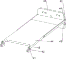
Fig. 1 is a schematic perspective view of the present invention.
Fig. 2 is a schematic perspective view of the transmission mechanism of the present invention.
Fig. 3 is a schematic perspective view of the rotary deformation mechanism of the present invention.
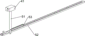
Fig. 4 is a schematic perspective view of the pushing mechanism of the present invention.
Fig. 5 is a schematic perspective view of the lift drive reciprocating mechanism of the present invention.
Fig. 6 is a schematic perspective view of a first embodiment of the present invention.
Fig. 7 is a perspective view of a second embodiment of the present invention.
Wherein the figures include the following reference numerals: 1-a bottom plate, 2-a support frame, 3-a transmission mechanism, 31-a first support seat, 32-a first fixing plate, 33-a second support seat, 34-a servo motor, 35-a sprocket, 36-a transmission chain, 37-a clamping plate, 38-a threaded rod, 4-a rotary deformation mechanism, 41-a clamping sleeve, 42-a second fixing plate, 43-a first rotating rod, 44-a carrying plate, 45-a fixing seat, 46-a second rotating rod, 47-a first connecting plate, 48-a third fixing plate, 5-a pushing mechanism, 51-a first connecting rod, 52-a sliding rail, 53-a rack, 6-an ascending driving reciprocating mechanism, 61-a third support seat, 62-a third rotating rod, 63-a second connecting plate, 64-a circular gear, 65-fixed rod, 66-second connecting rod, 67-top block, 68-carrying frame, 7-supporting plate, 8-top rod, 9-baffle, 10-hinged plate and 11-fourth rotating rod.
Detailed Description
The invention will be further described with reference to examples of embodiments shown in the drawings to which the invention is attached.
Example 1
A clothes placement protection student bed is shown in figures 1-5 and comprises a bottom plate 1, a support frame 2, a transmission mechanism 3, a rotary deformation mechanism 4, a pushing mechanism 5 and a lifting driving reciprocating mechanism 6, wherein the support frame 2 is arranged on the bottom plate 1, the transmission mechanism 3 is arranged on the rear side of the bottom plate 1, the rotary deformation mechanism 4 is arranged on the transmission mechanism 3, the pushing mechanism 5 is arranged between the bottom plate 1 and the rotary deformation mechanism 4, and the lifting driving reciprocating mechanism 6 is arranged on the bottom plate 1.
When the student need preserve or take out the clothing, alright control drive mechanism 3 moves, thereby make rotary deformation mechanism 4 move, in the time of rotary deformation mechanism 4 motion, can drive pushing mechanism 5 and remove, thereby make the motion of rise drive reciprocating mechanism 6, the user alright place the clothing in rise drive reciprocating mechanism 6 afterwards, perhaps take out the clothing, after the clothing access finishes, alright through 3 control rotary deformation mechanisms 4 of drive mechanism, pushing mechanism 5 and 6 resets of rise drive reciprocating mechanism, the student can have a rest on rotary deformation mechanism 4.
Drive mechanism 3 is including first supporting seat 31, first fixed plate 32, second supporting seat 33, servo motor 34, sprocket 35, drive chain 36, cardboard 37 and threaded rod 38, 1 rear side of bottom plate has first supporting seat 31 through the bolt rigid coupling, first supporting seat 31 front side is connected with first fixed plate 32, first fixed plate 32 upper portion is connected with second supporting seat 33, second supporting seat 33 upper portion has servo motor 34 through the bolt rigid coupling, both sides all are connected with sprocket 35 around the servo motor 34 output shaft, 2 rear portion left and right sides of support frame all are connected with cardboard 37, equal rotary type threaded rod 38 is equipped with on the cardboard 37, 38 rear end of threaded rod also is connected with sprocket 35, be connected with drive chain 36 between the sprocket 35 of homonymy.
When the student need preserve or take out the clothing, alright control servo motor 34 begins work, servo motor 34 can drive threaded rod 38 through driving sprocket 35 and drive chain 36 and rotate, thereby make rotatory texturing machine construct 4, pushing mechanism 5 and rise and drive reciprocating mechanism 6 and move, after the clothing access finishes, alright drive threaded rod 38 counter-rotation through servo motor 34, sprocket 35 and drive chain 36, thereby make rotatory texturing machine construct 4, pushing mechanism 5 and rise and drive reciprocating mechanism 6 and reset.
Rotatory deformation mechanism 4 is including cutting ferrule 41, second fixed plate 42, first bull stick 43, carry thing board 44, fixing base 45, second bull stick 46, first connecting plate 47 and third fixed plate 48, all there is cutting ferrule 41 through threaded connection on the threaded rod 38, all be connected with second fixed plate 42 on the cutting ferrule 41, equal rotary type is connected with first bull stick 43 on the second fixed plate 42, be connected with between the first bull stick 43 and carry thing board 44, be connected with fixing base 45 on the first supporting seat 31, 45 upper portion rotary types of fixing base are connected with second bull stick 46, the second bull stick 46 left and right sides all is connected with first connecting plate 47, first connecting plate 47 is connected with year thing board 44 rotary type, be connected with third fixed plate 48 between the first connecting plate 47.
When the threaded rod 38 rotates, the ferrule 41, the second fixing plate 42 and the first rotating rod 43 are driven to move to the rear side, so that the carrier plate 44 is rotated upward while moving to the rear side, and at the same time the first connection plate 47 and the third fixing plate 48 are also rotated upward, so that the object carrying plate 44 no longer blocks the upper part of the lifting driving reciprocating mechanism 6, and simultaneously, the cutting sleeve 41 can drive the pushing mechanism 5 to move when moving, thereby leading the lifting driving reciprocating mechanism 6 to move, being convenient for students to store and take clothes, when the clothes are stored and taken completely, the control threaded rod 38 rotates reversely, the cutting sleeve 41, the second fixing plate 42 and the first rotating rod 43 reset, the carrying plate 44, the second rotating rod 46, the first connecting plate 47 and the third fixing plate 48 reset accordingly, at the same time, the pushing mechanism 5 and the lifting driving reciprocating mechanism 6 are reset, so that the clothes in the lifting driving reciprocating mechanism 6 are protected.
The pushing mechanism 5 comprises a first connecting rod 51, a sliding rail 52 and a rack 53, the lower part of the cutting sleeve 41 is connected with the first connecting rod 51, the left side and the right side of the bottom plate 1 are fixedly connected with the sliding rail 52 through bolts, the sliding rail 52 is provided with the rack 53 in a sliding manner, and the rack 53 is connected with the first connecting rod 51.
When the cutting sleeve 41 moves towards the rear side, the first connecting rod 51 and the rack 53 are driven to move backwards, the ascending driving reciprocating mechanism 6 can move after the rack 53 moves backwards for a certain distance, and when the cutting sleeve 41 resets, the first connecting rod 51 and the rack 53 reset along with the movement, so that the ascending driving reciprocating mechanism 6 is driven to reset.
The ascending driving reciprocating mechanism 6 comprises a third supporting seat 61, a third rotating rod 62, a second connecting plate 63, a circular gear 64, a fixing rod 65, a second connecting rod 66, a top block 67 and a carrying frame 68, the left side and the right side of the bottom plate 1 are both connected with the third supporting seat 61, the upper part of the third supporting seat 61 is rotatably connected with the third rotating rod 62, the inner side of the third rotating rod 62 is connected with the second connecting plate 63, the outer side of the third rotating rod 62 is connected with the circular gear 64, the circular gear 64 is meshed with the rack 53, the rear part of the inner side of the second connecting plate 63 is connected with the fixing rod 65, the fixing rod 65 is rotatably connected with the second connecting rod 66, the second connecting rod 66 is rotatably connected with the top block 67, the upper part of the top block 67 is connected with the carrying frame 68.
When rack 53 backward move to with the circular gear 64 meshing after, just can drive circular gear 64, third bull stick 62 and second connecting plate 63 rotate, can drive kicking block 67 and year thing frame 68 rebound through dead lever 65 and second connecting rod 66 when second connecting plate 63 is rotatory, the student of being convenient for accesses the clothing, when rack 53 resets, just can make circular gear 64, third bull stick 62 and second connecting plate 63 counter-rotation, thereby make dead lever 65, second connecting rod 66, kicking block 67 and year thing frame 68 reset.
Example 2
On the basis of the embodiment 1, as shown in fig. 6 to 7, the device further comprises a supporting plate 7 and a push rod 8, the supporting plate 7 is connected to the middle of the bottom plate 1, the push rod 8 is connected to the upper portion of the supporting plate 7, and the push rod 8 is matched with the push block 67.
When the top block 67 is in a normal state, the top rod 8 can support the top block 67, and the fixing rod 65 and the second connecting rod 66 are prevented from being damaged by the gravity of the top block 67 and the carrying frame 68.
Still including baffle 9, articulated slab 10 and fourth bull stick 11, the equal rotary type in support frame 2 upper portion left and right sides is connected with fourth bull stick 11, is connected with articulated slab 10 on the fourth bull stick 11, is connected with baffle 9 between the articulated slab 10, baffle 9 with carry the cooperation of thing frame 68.
When accessing a small amount of clothes which are commonly used, the baffle plate 9 can be directly upwards screwed up, so that the baffle plate 9 can not block the front part of the loading frame 68 any more, then a student can access the clothes, and the student can access the clothes conveniently at ordinary times.
Finally, it should be noted that the above embodiments are only used for illustrating the technical solutions of the present invention and not for limiting the protection scope of the present invention, and although the present invention is described in detail with reference to the preferred embodiments, it should be understood by those skilled in the art that modifications or equivalent substitutions can be made on the technical solutions of the present invention without departing from the spirit and scope of the technical solutions of the present invention.
Claims (8)
1. The utility model provides a protection student bed is placed to clothing, characterized by, including:
a base plate (1);
the support frame (2) is arranged on the bottom plate (1);
the transmission mechanism (3) is arranged on the bottom plate (1);
the rotary deformation mechanism (4) is arranged on the transmission mechanism (3);
the pushing mechanism (5) is arranged between the bottom plate (1) and the rotary deformation mechanism (4);
and the lifting driving reciprocating mechanism (6) is arranged on the bottom plate (1).
2. A clothing placement protection student bed as claimed in claim 1 wherein the transmission mechanism (3) comprises:
a first support base (31) mounted on the base plate (1);
a first fixing plate (32) mounted on the first support base (31);
a second support base (33) mounted on the first fixing plate (32);
a servo motor (34) mounted on the second support base (33);
chain gears (35) mounted on both sides of an output shaft of the servo motor (34);
the clamping plates (37) are arranged on two sides of the support frame (2);
the threaded rod (38) is rotatably arranged on the clamping plate (37), and the threaded rod (38) is also connected with a chain gear (35);
and the transmission chain (36) is arranged between the chain gears (35) on the same side.
3. A clothing placement protection student bed as claimed in claim 2 wherein the rotary deformation mechanism (4) comprises:
the cutting sleeve (41) is arranged on the threaded rod (38) through threads;
the second fixing plate (42) is arranged on the clamping sleeve (41);
a first rotating rod (43) rotatably mounted on the second fixing plate (42);
a loading plate (44) installed between the first rotating rods (43);
a fixed seat (45) mounted on the first support seat (31);
the second rotating rod (46) is rotatably arranged on the fixed seat (45);
the first connecting plates (47) are arranged on two sides of the second rotating rod (46), and the first connecting plates (47) are rotatably connected with the object carrying plate (44);
and a third fixing plate (48) installed between the first connection plates (47).
4. A clothing placement protection student bed as claimed in claim 3 wherein the pushing mechanism (5) comprises:
the first connecting rod (51) is arranged on the clamping sleeve (41);
the sliding rails (52) are arranged on two sides of the bottom plate (1);
and the rack (53) is arranged on the sliding rail (52) in a sliding manner, and the rack (53) is connected with the first connecting rod (51).
5. A clothing placement safety student bed as claimed in claim 4 wherein the lifting drive reciprocating mechanism (6) comprises:
the third supporting seats (61) are arranged on two sides of the bottom plate (1);
a third rotating rod (62) rotatably mounted on the third support base (61);
a second connecting plate (63) mounted on one side of the third rotating rod (62);
the circular gear (64) is arranged on the other side of the third rotating rod (62), and the circular gear (64) is meshed with the rack (53);
a fixing rod (65) mounted on the second connecting plate (63);
a second connecting rod (66) rotatably mounted on the fixing rod (65);
the ejector block (67) is rotatably arranged between the second connecting rods (66);
and the carrying frame (68) is arranged on the top block (67), and the carrying frame (68) is in sliding fit with the support frame (2).
6. The clothes placement protection student bed as claimed in claim 5, further comprising:
a support plate (7) mounted on the base plate (1);
and the ejector rod (8) is arranged on the supporting plate (7), and the ejector rod (8) is matched with the ejector block (67).
7. The clothes placement protection student bed as claimed in claim 6, further comprising:
the fourth rotating rods (11) are rotatably arranged on two sides of the supporting frame (2);
the hinged plate (10) is arranged on the fourth rotating rod (11);
and the baffle (9) is arranged on the fourth rotating rod (11), and the baffle (9) is matched with the carrying frame (68).
8. A clothing placement protection student bed as claimed in claim 6 wherein the surface of the top bar (8) is rubber.
Priority Applications (1)
| Application Number | Priority Date | Filing Date | Title |
|---|---|---|---|
| CN202011464340.1A CN112336113B (en) | 2020-12-14 | 2020-12-14 | Clothes placement protection student bed |
Applications Claiming Priority (1)
| Application Number | Priority Date | Filing Date | Title |
|---|---|---|---|
| CN202011464340.1A CN112336113B (en) | 2020-12-14 | 2020-12-14 | Clothes placement protection student bed |
Publications (2)
| Publication Number | Publication Date |
|---|---|
| CN112336113A true CN112336113A (en) | 2021-02-09 |
| CN112336113B CN112336113B (en) | 2023-07-07 |
Family
ID=74427822
Family Applications (1)
| Application Number | Title | Priority Date | Filing Date |
|---|---|---|---|
| CN202011464340.1A Active CN112336113B (en) | 2020-12-14 | 2020-12-14 | Clothes placement protection student bed |
Country Status (1)
| Country | Link |
|---|---|
| CN (1) | CN112336113B (en) |
Citations (8)
| Publication number | Priority date | Publication date | Assignee | Title |
|---|---|---|---|---|
| CN201938858U (en) * | 2011-01-13 | 2011-08-24 | 张雪琪 | Bed |
| CN201958318U (en) * | 2010-11-17 | 2011-09-07 | 东莞市金柄源实业有限公司 | Storage bed frame opened and closed through remote control |
| CN104510213A (en) * | 2013-09-30 | 2015-04-15 | 金亚东 | Inflatable shockproof bed |
| CN106820743A (en) * | 2017-03-08 | 2017-06-13 | 王春霖 | A kind of anti-terrorism Antiseismic bed |
| CN206777124U (en) * | 2017-01-21 | 2017-12-22 | 陈继山 | A kind of intelligent bed |
| CN110464157A (en) * | 2019-09-06 | 2019-11-19 | 深圳厚积福鑫智能家居有限公司 | A kind of article-storable bed |
| CN211021797U (en) * | 2019-07-17 | 2020-07-17 | 麒盛科技股份有限公司 | Bed body structure |
| CN111920253A (en) * | 2020-07-03 | 2020-11-13 | 陈书琦 | Student bed with storage box |
-
2020
- 2020-12-14 CN CN202011464340.1A patent/CN112336113B/en active Active
Patent Citations (8)
| Publication number | Priority date | Publication date | Assignee | Title |
|---|---|---|---|---|
| CN201958318U (en) * | 2010-11-17 | 2011-09-07 | 东莞市金柄源实业有限公司 | Storage bed frame opened and closed through remote control |
| CN201938858U (en) * | 2011-01-13 | 2011-08-24 | 张雪琪 | Bed |
| CN104510213A (en) * | 2013-09-30 | 2015-04-15 | 金亚东 | Inflatable shockproof bed |
| CN206777124U (en) * | 2017-01-21 | 2017-12-22 | 陈继山 | A kind of intelligent bed |
| CN106820743A (en) * | 2017-03-08 | 2017-06-13 | 王春霖 | A kind of anti-terrorism Antiseismic bed |
| CN211021797U (en) * | 2019-07-17 | 2020-07-17 | 麒盛科技股份有限公司 | Bed body structure |
| CN110464157A (en) * | 2019-09-06 | 2019-11-19 | 深圳厚积福鑫智能家居有限公司 | A kind of article-storable bed |
| CN111920253A (en) * | 2020-07-03 | 2020-11-13 | 陈书琦 | Student bed with storage box |
Also Published As
| Publication number | Publication date |
|---|---|
| CN112336113B (en) | 2023-07-07 |
Similar Documents
| Publication | Publication Date | Title |
|---|---|---|
| CN111248628B (en) | Combined workbench for mechanical design | |
| CN112336113A (en) | Clothing is placed and is protected student's bed | |
| CN111843957A (en) | High-rise hidden recyclable warehouse material storage management mechanism | |
| CN214016533U (en) | Adjustable anti-collision tea table | |
| CN215126748U (en) | Works display device for art design | |
| CN212830070U (en) | Medical record management data storage device | |
| US1532728A (en) | Combination workstand and turntable | |
| CN105686416B (en) | A kind of multifunctional intellectual furniture | |
| CN211574638U (en) | Electric automatization processing equipment | |
| CN207674467U (en) | Submerged slag conveyor stopping device | |
| CN220656040U (en) | Medical cabinet body convenient to move | |
| CN214341301U (en) | High-box bed convenient to move and bed tail stool combined furniture | |
| CN219719221U (en) | Vegetable planting frame | |
| CN212489143U (en) | Logistics rack convenient to use | |
| CN216932486U (en) | Bed with can accomodate bed tail bench | |
| CN210462258U (en) | Notebook computer support with safeguard function | |
| CN217090062U (en) | Chair with storage function | |
| CN220815679U (en) | Fixing mechanism of tunnel waterproof board | |
| CN220484304U (en) | Logistics storage rack with adjustable height | |
| CN215724492U (en) | Adjustable foot margin assembly for refrigerator | |
| CN213958367U (en) | Hyperboloid teaching demonstration toolbox that possesses convenient storage | |
| CN212754951U (en) | Sofa | |
| CN218010787U (en) | Protection guardrail folded cascade trampoline | |
| CN216823941U (en) | Portable nursing bed | |
| CN216093809U (en) | Portable mechatronic laboratory bench |
Legal Events
| Date | Code | Title | Description |
|---|---|---|---|
| PB01 | Publication | ||
| PB01 | Publication | ||
| SE01 | Entry into force of request for substantive examination | ||
| SE01 | Entry into force of request for substantive examination | ||
| TA01 | Transfer of patent application right | ||
| TA01 | Transfer of patent application right |
Effective date of registration: 20230613 Address after: 528400 Tongmao Industrial Park, Xiaolan Town, Zhongshan City, Guangdong Province Applicant after: Guangdong Huasheng Furniture Group Co.,Ltd. Address before: Room 1025, Building 1, No. 368 Xuyuan, Xuyao Village, Zhonggu Town, Qingpu District, Shanghai 201700 Applicant before: Yu Wencheng |
|
| GR01 | Patent grant | ||
| GR01 | Patent grant |