CN112335294B - Emergency call method and user terminal - Google Patents
Emergency call method and user terminal Download PDFInfo
- Publication number
- CN112335294B CN112335294B CN201980043323.XA CN201980043323A CN112335294B CN 112335294 B CN112335294 B CN 112335294B CN 201980043323 A CN201980043323 A CN 201980043323A CN 112335294 B CN112335294 B CN 112335294B
- Authority
- CN
- China
- Prior art keywords
- plmn
- user terminal
- emergency call
- plmn list
- eplmn
- Prior art date
- Legal status (The legal status is an assumption and is not a legal conclusion. Google has not performed a legal analysis and makes no representation as to the accuracy of the status listed.)
- Active
Links
Images


Classifications
-
- H—ELECTRICITY
- H04—ELECTRIC COMMUNICATION TECHNIQUE
- H04W—WIRELESS COMMUNICATION NETWORKS
- H04W76/00—Connection management
- H04W76/50—Connection management for emergency connections
-
- H—ELECTRICITY
- H04—ELECTRIC COMMUNICATION TECHNIQUE
- H04W—WIRELESS COMMUNICATION NETWORKS
- H04W4/00—Services specially adapted for wireless communication networks; Facilities therefor
- H04W4/90—Services for handling of emergency or hazardous situations, e.g. earthquake and tsunami warning systems [ETWS]
-
- H—ELECTRICITY
- H04—ELECTRIC COMMUNICATION TECHNIQUE
- H04W—WIRELESS COMMUNICATION NETWORKS
- H04W4/00—Services specially adapted for wireless communication networks; Facilities therefor
- H04W4/02—Services making use of location information
- H04W4/029—Location-based management or tracking services
-
- H—ELECTRICITY
- H04—ELECTRIC COMMUNICATION TECHNIQUE
- H04W—WIRELESS COMMUNICATION NETWORKS
- H04W48/00—Access restriction; Network selection; Access point selection
- H04W48/18—Selecting a network or a communication service
-
- H—ELECTRICITY
- H04—ELECTRIC COMMUNICATION TECHNIQUE
- H04W—WIRELESS COMMUNICATION NETWORKS
- H04W8/00—Network data management
- H04W8/18—Processing of user or subscriber data, e.g. subscribed services, user preferences or user profiles; Transfer of user or subscriber data
- H04W8/20—Transfer of user or subscriber data
-
- H—ELECTRICITY
- H04—ELECTRIC COMMUNICATION TECHNIQUE
- H04W—WIRELESS COMMUNICATION NETWORKS
- H04W84/00—Network topologies
- H04W84/02—Hierarchically pre-organised networks, e.g. paging networks, cellular networks, WLAN [Wireless Local Area Network] or WLL [Wireless Local Loop]
- H04W84/04—Large scale networks; Deep hierarchical networks
- H04W84/042—Public Land Mobile systems, e.g. cellular systems
Abstract
The embodiment of the invention discloses an emergency call method and a user terminal, wherein the method comprises the following steps: acquiring an HPLMN and an EHPLMN from a user identity identification SIM card of a user terminal; receiving an emergency call operation of a user; responding to the emergency call operation of the user, receiving a Public Land Mobile Network (PLMN) list broadcasted by access network equipment, wherein the access network equipment is access network equipment under a multi-operator core network (MOCN), and the PLMN list comprises a plurality of PLMNs sharing the access network equipment; when the HPLMN or the EHPLMN exists in the PLMN list, determining the HPLMN or the EHPLMN in the PLMN list as an optimal PLMN; and carrying out emergency call through the core network of the optimal PLMN. Based on the method described in the first aspect, the emergency call center can successfully acquire the telephone number of the user terminal.
Description
Technical Field
The present invention relates to the field of terminal technologies, and in particular, to an emergency call method and a user terminal.
Background
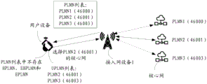
An emergency call (emergency call) refers to dialing an alarm or distress number such as 112, 110, 119, 120 with a cell phone. The urgency of these numbers has led countries to specify that they can use any network available at the time. Fig. 1 is a schematic diagram of a user terminal placing an emergency call through a MOCN (multi-operator network) network. A MOCN network refers to a set of core network nodes that a wireless network can simultaneously connect to multiple operators. As shown in fig. 1, PLMN1 of operator 1, PLMN2 of operator 2, and PLMN3 of operator 3 are MOCN networks, and PLMN1 of operator 1, PLMN2 of operator 2, and PLMN3 of operator 3 share one base station, but their core networks are independent of each other.
As shown in fig. 1, the subscriber terminal makes an emergency call using a Subscriber Identity Module (SIM) of an operator 1. During the emergency call of the user terminal, the user terminal may select one of three communication paths a, b and c to communicate with the emergency call center as indicated by the dotted arrow. If the user terminal selects communication path a to make an emergency call to the emergency call center, the core network of PLMN1 can recognize the account opening information of the SIM card used by the user terminal, since the SIM card belongs to the one issued by operator 1. An emergency call is thus made to an emergency call centre via the core network of the PLMN1, which is able to identify the telephone number of the subscriber. If the user terminal selects the communication path b or c to communicate with the emergency call center, the core networks of the PLMN2 and PLMN3 do not have the account opening information of the SIM card because the SIM card used by the user terminal is not the home card of the operator 2 and operator 3, so that the emergency call center cannot identify the mobile phone number of the user. If the user terminal selects the communication path b or c to communicate with the emergency call center when an emergency call is dialed, the number of the user cannot be acquired, which will bring a great obstacle to rescue, for example, a rescue team cannot dial back a help seeking user.
Therefore, how to enable the emergency call center to successfully acquire the telephone number of the help-seeking user is an urgent problem to be solved at present.
Disclosure of Invention
The embodiment of the invention discloses an emergency call method and a user terminal, which are beneficial for an emergency call center to successfully acquire the telephone number of a help-seeking user.
In a first aspect, an embodiment of the present application provides an emergency call method, where the method includes: acquiring PLMN information from a user identity identification SIM card of a user terminal, wherein the PLMN information comprises a Home Public Land Mobile Network (HPLMN) and an Equivalent Home Public Land Mobile Network (EHPLMN); receiving an emergency call operation of a user; responding to the emergency call operation of the user, receiving a Public Land Mobile Network (PLMN) list broadcasted by access network equipment, wherein the access network equipment is access network equipment under a multi-operator core network (MOCN), and the PLMN list comprises a plurality of PLMNs sharing the access network equipment; when the HPLMN or the EHPLMN exists in the PLMN list, determining the HPLMN or the EHPLMN in the PLMN list as an optimal PLMN; and carrying out emergency call through the core network of the optimal PLMN. Specifically, after receiving a PLMN list broadcast by the access network device, it may be determined whether an HPLMN or EHPLMN exists in the PLMN list, and when the HPLMN or EHPLMN exists in the PLMN list, it is determined that the HPLMN or EHPLMN in the PLMN list is the optimal PLMN.
And the PLMN with the highest association degree with the SIM card of the user terminal in the PLMN list is the HPLMN or the EHPLMN. The core networks of the HPLMN and the EHPLMN are provided with account opening information of the SIM card of the user terminal. The account opening information of the SIM card can comprise information such as the telephone number of the SIM card. Therefore, the core network of the HPLMN or the EHPLMN is used for making an emergency call, and the core network of the HPLMN or the EHPLMN can inform the emergency call center of the telephone number of the SIM card, so that the emergency call center can successfully acquire the telephone number of the user terminal. Therefore, the method described in the first aspect is beneficial for the emergency call center to successfully acquire the telephone number of the user terminal.
Optionally, after obtaining the PLMN information from the SIM card of the user terminal, the PLMN information may be stored in the memory of the user terminal, so that the user terminal may obtain the HPLMN or EHPLMN more quickly in the following.
Optionally, after the user terminal receives the emergency call operation of the user, the location information of the user terminal may be obtained; the user terminal can also send the location information of the user terminal to the emergency call center through the core network of the optimal PLMN. Based on the optional implementation mode, the emergency call center can successfully acquire the telephone number of the user terminal, and the position information of the user terminal can be successfully sent to the emergency call center.
Optionally, after receiving the emergency call operation of the user, the user terminal may further obtain personal information of the user, and send the personal information of the user to the emergency call center through the core network of the optimal PLMN. Optionally, the type of the emergency call and the personal information of the user have a corresponding relationship, and the user terminal may obtain the corresponding personal information of the user according to the type of the emergency call. Optionally, after the user terminal acquires the user personal information according to the type of the emergency call, the acquired user personal information may be displayed. Optionally, the user may also modify the displayed personal information of the user. After the modification is completed, the sending instruction can be clicked and confirmed, and the user terminal sends the personal information of the user to the emergency call center through the core network of the optimal PLMN. Or, the user may not modify the displayed user personal information, and after the user terminal displays the acquired user personal information, the user may directly click the confirmation sending button. And after receiving the confirmation sending instruction, the user terminal sends the personal information of the user to the emergency call center through the core network of the optimal PLMN. After the user terminal displays the acquired personal information of each user, the user can click a cancel sending button. And after receiving the command of canceling the transmission, the user terminal does not transmit the personal information of the user to the emergency call center. By implementing the optional mode, the user can preset user personal information corresponding to different types of emergency calls, and the user personal information can be sent to the emergency call center in time during the emergency call, so that the success rate of rescue is improved.
Optionally, after the user terminal performs the emergency call through the HPLMN or EHPLMN core network, if the user terminal detects that the emergency call fails, the user terminal may determine whether an EPLMN exists in the PLMN list, and if the EPLMN exists, perform the emergency call through the EPLMN core network. In this optional manner, if the emergency call through the core network of the HPLMN or EHPLMN fails, the user terminal may automatically make the emergency call again through the core network of the EPLMN without the user performing the emergency call operation again. In practical applications, the signal quality of the HPLMN or EHPLMN may not be good, which may result in failure of the emergency call. Therefore, when the emergency call through the HPLMN or the EHPLMN fails, the core network of other PLMN is selected again to carry out the emergency call, which is beneficial to improving the success rate of the emergency call.
Optionally, if the duration of the emergency call reaches the preset duration or the failure frequency of the emergency call reaches the preset frequency, the user terminal prompts the user that the call is failed.
Optionally, when the HPLMN and the EHPLMN do not exist in the PLMN list and an equivalent public land mobile network EPLMN exists in the PLMN list, determining the EPLMN in the PLMN list as the optimal PLMN. Specifically, when the HPLMN and the EHPLMN do not exist in the PLMN list, it may be determined whether an EPLMN exists in the PLMN list, and when the EPLMN exists in the PLMN list, it may be determined that the EPLMN in the PLMN list is the optimal PLMN. And when the HPLMN or the EHPLMN does not exist in the PLMN list, the EPLMN in the PLMN list is the PLMN with the highest association degree with the SIM card of the user terminal. Therefore, based on the optional implementation mode, the emergency call center can successfully acquire the telephone number of the user terminal.
Optionally, the user terminal may receive the EPLMN list before the user terminal receives the emergency call instruction. Optionally, the user terminal may store the EPLMN in the memory, or in another location.
Optionally, if there are multiple EPLMNs included in the PLMN list, it may be determined that an EPLMN with the best signal quality among the multiple EPLMNs is the optimal PLMN, or the EPLMN with the largest number of times of use among the multiple EPLMNs is the optimal PLMN. Or, the selection priority of each EPLMN during the emergency call may be preset, and the user terminal selects one EPLMN from the plurality of EPLMNs to perform the emergency call according to the preset selection priority of each EPLMN.
Optionally, after the user terminal makes an emergency call through the core network of the EPLMN, if the user terminal detects that the emergency call fails, the user terminal may determine whether the UPLMN list includes the UPLMN, and if the UPLMN list includes the UPLMN, make the emergency call again through the core network of the UPLMN. In this optional manner, if the emergency call through the core network of the EPLMN fails, the user terminal may automatically make the emergency call again through the core network of the UPLMN without the user performing the emergency call operation again. In practical applications, the signal quality of the EPLMN may be poor, possibly resulting in an emergency call failure. Therefore, when the emergency call through the EPLMN fails, the emergency call can be carried out through the core network of other PLMN again, which is beneficial to improving the success rate of the emergency call.
Optionally, when the HPLMN, the EHPLMN, and the EPLMN are not present in the PLMN list and a user controlled public land mobile network UPLMN is present in the PLMN list, determining that the UPLMN in the PLMN list is the optimal PLMN. Specifically, when the HPLMN, the EHPLMN, and the EPLMN are not present in the PLMN list, it may be determined whether the UPLMN is present in the PLMN list, and when the UPLMN is present in the PLMN list, it is determined that the EPLMN in the PLMN list is the optimal PLMN. And when the HPLMN, the EHPLMN and the EPLMN do not exist in the PLMN list, the UPLMN in the PLMN list is the PLMN with the highest association degree with the SIM card of the user terminal. Therefore, the user terminal selects the core network of the UPLMN to carry out emergency call, and the emergency call center can successfully acquire the telephone number of the user terminal.
Optionally, the PLMN information acquired by the user terminal may further include a UPLMN.
Optionally, if the number of the UPLMNs included in the PLMN list is multiple, the UPLMN with the best signal quality in the multiple UPLMNs may be determined as the optimal PLMN, or the UPLMN with the highest number of users in the multiple UPLMNs may be determined as the optimal PLMN. Or, the selection priority of each UPLMN during the emergency call may be preset, and the user terminal selects one UPLMN from the plurality of UPLMNs according to the preset selection priority of each UPLMN to perform the emergency call.
Optionally, after the user terminal performs the emergency call through the core network of the UPLMN, if the user terminal detects that the emergency call fails, the user terminal may determine whether an OPLMN exists in the PLMN list, and if the OPLMN exists, perform the emergency call again through the core network of the OPLMN. In this alternative mode, if the emergency call through the core network of the OPLMN fails, the user terminal may automatically make the emergency call again through the core network of the OPLMN without the user performing the emergency call operation again. In practical applications, the signal quality of the UPLMN may be poor, possibly resulting in failure of the emergency call. Therefore, when the emergency call fails through the UPLMN, the emergency call can be carried out through the core networks of other PLMNs again, and the success rate of the emergency call is improved.
Optionally, when the HPLMN, the EHPLMN, the EPLMN, and the UPLMN are not present in the PLMN list, and an operator-controlled public land mobile network OPLMN is present in the PLMN list, determining that the OPLMN in the PLMN list is the optimal PLMN. Specifically, when the HPLMN, the EHPLMN, the EPLMN, and the UPLMN are not present in the PLMN list, it may be determined whether an OPLMN is present in the PLMN list, and when the OPLMN is present in the PLMN list, it is determined that the OPLMN in the PLMN list is the optimal PLMN. And when the HPLMN, the EHPLMN, the EPLMN and the UPLMN do not exist in the PLMN list, the OPLMN in the PLMN list is the PLMN with the highest association degree with the SIM card of the user terminal. Therefore, the user terminal selects the core network of the OPLMN to carry out emergency call, and the emergency call center can successfully acquire the telephone number of the user terminal.
Optionally, the PLMN information acquired by the user terminal may further include an OPLMN.
Optionally, if the number of OPLMNs included in the PLMN list is multiple, it may be determined that an OPLMN with the best signal quality among the multiple OPLMNs is the optimal PLMN, or it may be determined that a core network of an OPLMN with the largest number of users in the multiple OPLMNs uses the most number of times to perform an emergency call. Or, the selection priority of each OPLMN during the emergency call may be preset, and the user terminal selects one OPLMN from the plurality of OPLMNs to perform the emergency call according to the preset selection priority of each OPLMN.
Optionally, when the HPLMN, EHPLMN, EPLMN, UPLMN, and OPLMN do not exist in the PLMN list, the PLMN with the best signal quality in the PLMN list is determined to be the optimal PLMN. Specifically, when the HPLMN, the EHPLMN, the EPLMN, and the UPLMN are not present in the PLMN list, it may be determined whether an OPLMN is present in the PLMN list, and when the OPLMN is not present in the PLMN list, it is determined that a PLMN with the best signal quality in the PLMN list is the optimal PLMN.
Optionally, if the user terminal determines that the PLMN with the best signal quality in the PLMN list is the optimal PLMN, the user terminal outputs a prompt message, where the prompt message is used to prompt that the emergency call center may not successfully acquire the telephone number of the calling party. By implementing the method, the user can acquire whether the emergency call center can successfully acquire the telephone number of the calling user so as to inform the emergency call center of the telephone number of the calling user in other ways, for example, the user can orally inform the emergency call center of the telephone number when the emergency call center connects an incoming call.
Optionally, after receiving the emergency call operation and the PLMN list, the user terminal may determine the optimal PLMN from the PLMN list according to the following priority order of the optimal PLMN. The priority order of the optimal PLMN may be: HPLMN and EHPLMN > EPLMN > UPLMN > OPLMN > PLMN with the best signal quality. Namely, the user terminal firstly determines whether the HPLMN or the EHPLMN exists in the PLMN list, and if the HPLMN or the EHPLMN exists in the PLMN list, the HPLMN or the EHPLMN is determined to be the optimal PLMN. If it is determined that no HPLMN or EHPLMN exists in the PLMN list, it is then determined whether an EPLMN exists in the PLMN list. And if the EPLMN exists in the PLMN list, determining the EPLMN as the optimal PLMN. If it is determined that the EPLMN does not exist in the PLMN list, it is then determined whether the UPLMN exists in the PLMN list. And if the UPLMN exists in the PLMN list, determining the UPLMN as the optimal PLMN. If no UPLMN exists in the PLMN list, determining whether an OPLMN exists in the PLMN list. And if the OPLMN exists in the PLMN list, determining the OPLMN as the optimal PLMN. And if the OPLMN does not exist in the PLMN list, determining the PLMN with the best signal quality in the PLMN list as the optimal PLMN. The optimal PLMN is determined through the priority sequence, and the success rate of the emergency call center for acquiring the telephone number of the user terminal is improved.
In a second aspect, a user terminal is provided, which is capable of executing the method described in the first aspect or the possible implementation manner of the first aspect. The function can be realized by hardware, and can also be realized by executing corresponding software by hardware. The hardware or software includes one or more units corresponding to the above functions. The unit may be software and/or hardware. Based on the same inventive concept, the principle and the beneficial effects of the ue for solving the problem may refer to the principle and the beneficial effects of the first aspect or the possible implementation manner of the first aspect, and repeated details are not repeated.
In a third aspect, a user terminal is provided, which includes: the processor is connected with the memory and the communication interface; the memory for storing instructions; a communication interface for communicating with other devices; the processor is configured to execute the instructions in the memory, so that the user terminal executes the method described in the first aspect or the possible implementation manner of the first aspect, and for the implementation and the beneficial effects of the user terminal for solving the problem, reference may be made to the principle and the beneficial effects of the possible implementation manner of the first aspect or the first aspect, and repeated details are not repeated.
In a fourth aspect, a computer program product is provided, which, when run on a computer, causes the computer to perform the method described in the first aspect or the possible implementation manner of the first aspect.
In a fifth aspect, a chip system is provided, which includes a processor and an interface circuit, the interface circuit being coupled to the processor, the processor being configured to execute a computer program or instructions to implement the method according to the first aspect or the possible implementation manner of the first aspect; the interface circuit is used for communicating with other modules outside the chip system.
A sixth aspect provides a computer-readable storage medium having stored therein instructions, which, when run on a computer, cause the computer to perform the method described in the above first aspect or possible implementation manner of the first aspect.
Drawings
In order to more clearly illustrate the technical solutions in the embodiments of the present invention, the drawings needed to be used in the embodiments will be briefly described below, and it is obvious that the drawings in the following description are only some embodiments of the present invention, and it is obvious for those skilled in the art that other drawings can be obtained according to these drawings without creative efforts.
Fig. 1 is a schematic diagram of an existing emergency call provided by an embodiment of the present invention;
FIG. 2 is a diagram of a system architecture according to an embodiment of the present invention;
fig. 3 is a flowchart illustrating an emergency call method according to an embodiment of the present invention;
fig. 4 is a schematic diagram of an emergency call provided by an embodiment of the present invention;
fig. 5 is a schematic diagram of another emergency call provided by an embodiment of the present invention;
fig. 6 is a flowchart illustrating another emergency call method according to an embodiment of the present invention;
fig. 7 is a flowchart illustrating a further emergency call method according to an embodiment of the present invention;
fig. 8 is a schematic diagram of yet another emergency call provided by an embodiment of the present invention;
fig. 9 is a schematic diagram of yet another emergency call provided by an embodiment of the present invention;
fig. 10 is a schematic diagram of yet another emergency call provided by an embodiment of the present invention;
fig. 11 is a schematic diagram of yet another emergency call provided by an embodiment of the present invention;
fig. 12 is a schematic structural diagram of a user terminal according to an embodiment of the present invention;
fig. 13 is a schematic structural diagram of another user terminal according to an embodiment of the present invention.
Fig. 14 is a schematic diagram of a software system of a user terminal according to an embodiment of the present invention.
Detailed Description
In order to make the objects, technical solutions and advantages of the present invention clearer, the technical solutions of the embodiments of the present invention will be described below with reference to the accompanying drawings.
In order to enable an emergency call center to successfully acquire a telephone number of a help-seeking user, the embodiment of the application provides an emergency call method and a user terminal.
To facilitate an understanding of embodiments of the present invention, the following first presents specific terms used in the practice of the present invention:
public Land Mobile Network (PLMN): refers to a network established and operated by a government or its approved operator for the purpose of providing land mobile communication services to the public. The PLMN is composed of a Mobile Country Code (MCC) and a Mobile Network Code (MNC). For example, one PLMN for china mobile is 46000, where 460 is MCC and 00 is MNC.
Home Public Land Mobile Network (HPLMN): a PLMN to which the end user belongs. That is, the Mobile Country Code (MCC) and the Mobile Network Code (MNC) included in the international mobile subscriber identity number (IMSI) on the USIM card are consistent with the MCC and MNC on the HPLMN. For a certain user, there is only one HPLMN.
Equivalent Home Public Land Mobile Network (EHPLMN): is a PLMN that is co-located with the home PLMN currently selected by the user terminal. Operators corresponding to the HPLMN may have different PLMNs, for example, china mobile has three PLMNs, PLMN (46000), PLMN (46002), and PLMN (46007). The PLMN (46002) and the PLMN (46007) are EHPLMNs relative to the PLMN (46000), and an operator may write the SIM card before the SIM card leaves a factory.
Equivalent PLMN (equivalent public land mobile network, EPLMN): refers to a PLMN which is in the same position as the PLMN currently selected by the user terminal and has the same priority. The EPLMN mainly addresses the user residence and roaming policies of the shared network with the original network. An operator may configure the EPLMN network and communication network resource sharing may be implemented between these networks. From a service perspective, it enables communication network resource sharing between network resources of different operators, or between different PLMNs defined by the same operator.
For example, PLMN (46000) of the mobile operator covers shenzhen and PLMN (46001) of the unicom operator covers hong kong. The mobile operator and the operator of the communication can agree in advance that the PLMN (46000) and the PLMN (46001) are EPLMN. The positions between the PLMN (46000) and the PLMN (46001) are completely equal, and the PLMN (46000) and the PLMN (46001) share account opening information of a user. If the user terminal registers the PLMN (46000) in Shenzhen, after the registration is successful, the user terminal can receive an EPLMN list sent by a core network of the PLMN (46000), wherein the EPLMN list comprises the PLMN (46001). When the user terminal enters hong kong from shenzhen, the user terminal can register the PLMN (46001) in hong kong for communication because the PLMN (46001) is the EPLMN of the PLMN (46000).
User controlled public land mobile network (user controlled PLMN, UPLMN): is a PLMN selection related parameter stored on the USIM card.
Operator controlled public land mobile network (OPLMN): is a PLMN selection related parameter stored on the USIM card.
In order to better understand the embodiments of the present application, the following description is provided for a system architecture to which the embodiments of the present application can be applied:
fig. 2 is a schematic diagram of a system architecture according to an embodiment of the present application. As shown in fig. 2, the system architecture includes a user terminal, an access network device 1, and a core network sharing at least two PLMNs of the access network device 1. In fig. 2, PLMN1(46000), PLMN2(46001), and PLMN3(46003) share the access network device as an example, but in actual application, other PLMNs may share the access network device, or two or more PLMNs may share the access network device. That is, the network in which the user terminal, the access network device 1, the core network of the PLMN1(46000), the core network of the PLMN2(46001), and the core network of the PLMN3(46003) shown in fig. 2 are located is an MOCN network.
As shown in fig. 2, the system architecture further includes an access network device 2. Fig. 2 illustrates an example of the access network device 2 being connected to a core network of the PLMN4 (46002). It should be noted that the wireless communication technology adopted by the access network device 2 is different from the wireless communication technology adopted by the access network device 1, and the wireless communication technology adopted by the access network device 2 does not support the voice call service.
For example, if the 4G network does not support the voice call service and the 3G/2G network can support the voice call service, in this scenario, the wireless communication technology adopted by the access network device 2 may be a 4G wireless communication technology, and the wireless communication technology adopted by the access network device 1 may be a 3G/2G wireless communication technology. If the 5G network does not support the voice call service and the 4G/3G/2G network can support the voice call service, in this scenario, the wireless communication technology adopted by the access network device 2 may be a 5G wireless communication technology, and the wireless communication technology adopted by the access network device 1 may be a 4G/3G/2G wireless communication technology.
If the network currently registered by the user terminal does not support the voice call service, when the user terminal makes a call or has an incoming call, the user terminal automatically disconnects the currently registered network and drops to the network capable of supporting the voice call service to complete the voice call. For example, if the access network device 2 in fig. 2 employs a 4G wireless communication technology, and the access network device 1 employs a 3G wireless communication technology, the 4G wireless communication technology does not support voice call service. If the user equipment has registered the PLMN4(46002), after the user equipment receives the emergency call operation of the user, the user equipment needs to disconnect the PLMN4 of the 4G network (46002), re-register the user equipment to a PLMN of the 3G network, and perform the emergency call through the core network of the re-registered PLMN. In the existing practical application, after receiving an emergency call operation, a user terminal may randomly select a PLMN in an MOCN network to make an emergency call, and since a core network of the randomly selected PLMN may not have SIM card account opening information of a user, the emergency call is made through the core network of the randomly selected PLMN, which may result in that an emergency call center may not successfully acquire a telephone number of a distress user. In the embodiment of the present application, after receiving the emergency call operation, the user terminal may select a core network of a PLMN in the MOCN network with the highest association degree with the SIM card of the user terminal to perform the emergency call. The method and the device have the advantages that the SIM card account opening information of a common user in the core network of the PLMN under the MOCN network with the highest SIM card association degree of the user terminal is beneficial to enabling an emergency call center to successfully acquire the telephone number of the help seeking user by implementing the embodiment of the application.
The access network device may provide communication coverage for a specific geographic area, and may communicate with a terminal device located in the coverage area, and the access network device may support communication protocols of different systems or may support different communication modes. For example, the access network device may be an evolved Node B (eNB or eNodeB) in an LTE system, or a radio network controller in a Cloud Radio Access Network (CRAN), or may be an access network device in a fifth generation (5G) network, such as a new generation Node B (gnnodeb), or may be a small station, a micro station, or a Transmission Reception Point (TRP), or may be an access network device in a relay station, an access point, or a PLMN that is evolved in the future, or the like.
The user terminal may refer to an access terminal, a User Equipment (UE), a subscriber unit, a subscriber station, a mobile station, a remote terminal, a mobile terminal, a user terminal, a wireless communication device, a user agent, or a user equipment. An access terminal may be a cellular phone, a cordless phone, a Session Initiation Protocol (SIP) phone, a Wireless Local Loop (WLL) station, a Personal Digital Assistant (PDA), a handheld device with wireless communication capability, a computing device or other processing device connected to a wireless modem, a vehicle mounted device, a wearable device, a terminal device in the internet of things, a virtual reality device, a terminal device in a future 5G network, a terminal device in a future evolved Public Land Mobile Network (PLMN), or the like.
In order to better understand the embodiment of the present application, the following describes the structure of the user terminal according to the embodiment of the present application:
fig. 1 shows a schematic structural diagram of a user terminal 1300. The user terminal 1300 may include a processor 1310, an external memory interface 1320, an internal memory 1321, a Universal Serial Bus (USB) interface 1330, a charging management module 1340, a power management module 1341, a battery 1342, an antenna 1, an antenna 2, a mobile communication module 1350, a wireless communication module 1360, an audio module 1370, a speaker 1370A, a receiver 1370B, a microphone 1370C, an earphone interface 1370D, a sensor module 1380, keys 1390, a motor 1391, an indicator 1392, a camera 1393, a display 1394, and a Subscriber Identity Module (SIM) card interface 1395, etc. The sensor module 1380 may include a pressure sensor 1380A, a gyro sensor 1380B, an air pressure sensor 1380C, a magnetic sensor 1380D, an acceleration sensor 1380E, a distance sensor 1380F, a proximity light sensor 1380G, a fingerprint sensor 1380H, a temperature sensor 1380J, a touch sensor 1380K, an ambient light sensor 1380L, a bone conduction sensor 1380M, and the like.
It is to be understood that the illustrated structure of the embodiment of the present invention does not specifically limit the user terminal 1300. In other embodiments of the present application, user terminal 1300 may include more or fewer components than shown, or some components may be combined, some components may be split, or a different arrangement of components. The illustrated components may be implemented in hardware, software, or a combination of software and hardware.
The controller can generate an operation control signal according to the instruction operation code and the timing signal to complete the control of instruction fetching and instruction execution.
A memory may also be provided in processor 1310 for storing instructions and data. In some embodiments, the memory in the processor 1310 is a cache memory. The memory may hold instructions or data that have just been used or recycled by the processor 1310. If the processor 1310 needs to reuse the instructions or data, it may call directly from the memory. Avoiding repeated accesses reduces the latency of the processor 1310, thereby increasing the efficiency of the system.
In some embodiments, processor 1310 may include one or more interfaces. The interface may include an integrated circuit (I2C) interface, an integrated circuit built-in audio (I2S) interface, a Pulse Code Modulation (PCM) interface, a universal asynchronous receiver/transmitter (UART) interface, a Mobile Industry Processor Interface (MIPI), a general-purpose input/output (GPIO) interface, a Subscriber Identity Module (SIM) interface, and/or a Universal Serial Bus (USB) interface, etc.
The I2C interface is a bi-directional synchronous serial bus that includes a serial data line (SDA) and a Serial Clock Line (SCL). In some embodiments, processor 1310 may include multiple sets of I2C buses. The processor 1310 may be coupled to the touch sensor 1380K, the charger, the flash, the camera 1393, etc. via different I2C bus interfaces, respectively. For example: the processor 1310 may be coupled to the touch sensor 1380K through an I2C interface, such that the processor 1310 and the touch sensor 1380K communicate through an I2C bus interface to enable touch functionality of the user terminal 1300.
The I2S interface may be used for audio communication. In some embodiments, processor 1310 may include multiple sets of I2S buses. Processor 1310 may be coupled to audio module 1370 via an I2S bus to enable communication between processor 1310 and audio module 1370. In some embodiments, the audio module 1370 may transmit audio signals to the wireless communication module 1360 through the I2S interface, enabling answering calls through bluetooth headsets.
The PCM interface may also be used for audio communication, sampling, quantizing and encoding analog signals. In some embodiments, the audio module 1370 and the wireless communication module 1360 may be coupled through a PCM bus interface. In some embodiments, the audio module 1370 may also transmit audio signals to the wireless communication module 1360 through the PCM interface, so as to receive phone calls through the bluetooth headset. Both the I2S interface and the PCM interface may be used for audio communication.
The UART interface is a universal serial data bus used for asynchronous communications. The bus may be a bidirectional communication bus. It converts the data to be transmitted between serial communication and parallel communication. In some embodiments, a UART interface is generally used to connect the processor 1310 with the wireless communication module 1360. For example: the processor 1310 communicates with a bluetooth module in the wireless communication module 1360 through a UART interface to implement a bluetooth function. In some embodiments, the audio module 1370 may transmit the audio signal to the wireless communication module 1360 through the UART interface, so as to realize the function of playing music through the bluetooth headset.
The MIPI interface can be used to connect the processor 1310 with peripheral devices such as the display 1394 and the camera 1393. The MIPI interface includes a Camera Serial Interface (CSI), a Display Serial Interface (DSI), and the like. In some embodiments, processor 1310 and camera 1393 communicate through a CSI interface, enabling the capture functionality of user terminal 1300. The processor 1310 and the display screen 1394 communicate via the DSI interface, and the display function of the user terminal 1300 is realized.
The GPIO interface may be configured by software. The GPIO interface may be configured as a control signal and may also be configured as a data signal. In some embodiments, a GPIO interface may be used to connect the processor 1310 with the camera 1393, the display 1394, the wireless communication module 1360, the audio module 1370, the sensor module 1380, and so on. The GPIO interface may also be configured as an I2C interface, an I2S interface, a UART interface, a MIPI interface, and the like.
The USB interface 1330 is an interface conforming to the USB standard specification, and may specifically be a Mini USB interface, a Micro USB interface, a USB Type C interface, or the like. The USB interface 1330 may be used to connect a charger to charge the user terminal 1300, or may be used to transmit data between the user terminal 1300 and peripheral devices. And the earphone can also be used for connecting an earphone and playing audio through the earphone. The interface may also be used to connect other user terminals, such as AR devices and the like.
It should be understood that the interface connection relationship between the modules in the embodiment of the present invention is only an exemplary illustration, and does not form a structural limitation on the user terminal 1300. In other embodiments of the present application, the user terminal 1300 may also adopt different interface connection manners or a combination of multiple interface connection manners in the above embodiments.
The charge management module 1340 is used to receive charging input from the charger. The charger may be a wireless charger or a wired charger. In some wired charging embodiments, the charging management module 1340 may receive charging inputs from a wired charger via the USB interface 1330. In some wireless charging embodiments, the charging management module 1340 may receive wireless charging input through a wireless charging coil of the user terminal 1300. The charging management module 1340 can also supply power to the user terminal through the power management module 1341 while charging the battery 1342.
The power management module 1341 is used to connect the battery 1342, the charging management module 1340 and the processor 1310. The power management module 1341 receives input from the battery 1342 and/or the charging management module 1340, and provides power to the processor 1310, the internal memory 1321, the display 1394, the camera 1393, and the wireless communication module 1360. The power management module 1341 may also be used to monitor parameters such as battery capacity, battery cycle count, and battery state of health (leakage, impedance). In some other embodiments, the power management module 1341 may also be disposed in the processor 1310. In other embodiments, the power management module 1341 and the charge management module 1340 can be disposed in the same device.
The wireless communication function of the user terminal 1300 can be implemented by the antenna 1, the antenna 2, the mobile communication module 1350, the wireless communication module 1360, the modem processor, the baseband processor, and the like.
The antennas 1 and 2 are used for transmitting and receiving electromagnetic wave signals. Each antenna in user terminal 1300 may be used to cover a single or multiple communication bands. Different antennas can also be multiplexed to improve the utilization of the antennas. For example: the antenna 1 may be multiplexed as a diversity antenna of a wireless local area network. In other embodiments, the antenna may be used in conjunction with a tuning switch.
The mobile communication module 1350 may provide a solution for wireless communication including 2G/3G/4G/5G, etc. applied to the user terminal 1300. The mobile communication module 1350 may include at least one filter, a switch, a power amplifier, a Low Noise Amplifier (LNA), and the like. The mobile communication module 1350 can receive electromagnetic waves from the antenna 1, filter, amplify, etc. the received electromagnetic waves, and transmit the electromagnetic waves to the modem processor for demodulation. The mobile communication module 1350 can also amplify the signal modulated by the modem processor, and convert the signal into electromagnetic wave through the antenna 1 to radiate the electromagnetic wave. In some embodiments, at least some of the functional modules of the mobile communication module 1350 may be disposed in the processor 1310. In some embodiments, at least some of the functional modules of the mobile communication module 1350 may be disposed in the same device as at least some of the modules of the processor 1310.
The modem processor may include a modulator and a demodulator. The modulator is used for modulating a low-frequency baseband signal to be transmitted into a medium-high frequency signal. The demodulator is used for demodulating the received electromagnetic wave signal into a low-frequency baseband signal. The demodulator then passes the demodulated low frequency baseband signal to a baseband processor for processing. The low frequency baseband signal is processed by the baseband processor and then transferred to the application processor. The application processor outputs a sound signal through an audio device (not limited to the speaker 1370A, the receiver 1370B, and the like), or displays an image or video through the display screen 1394. In some embodiments, the modem processor may be a stand-alone device. In other embodiments, the modem processor may be separate from the processor 1310, and may be located in the same device as the mobile communication module 1350 or other functional modules.
The wireless communication module 1360 may provide solutions for wireless communication applied to the user terminal 1300, including Wireless Local Area Networks (WLANs) (e.g., wireless fidelity (Wi-Fi) networks), bluetooth (bluetooth, BT), Global Navigation Satellite System (GNSS), Frequency Modulation (FM), Near Field Communication (NFC), Infrared (IR), and the like. The wireless communication module 1360 may be one or more devices that integrate at least one communication processing module. The wireless communication module 1360 receives electromagnetic waves via the antenna 2, performs frequency modulation and filtering processing on the electromagnetic wave signal, and transmits the processed signal to the processor 1310. Wireless communication module 1360 may also receive signals to be transmitted from processor 1310, frequency modulate, amplify, and convert to electromagnetic radiation via antenna 2.
In some embodiments, antenna 1 of user terminal 1300 is coupled to mobile communication module 1350 and antenna 2 is coupled to wireless communication module 1360, such that user terminal 1300 may communicate with networks and other devices via wireless communication techniques. The wireless communication technology may include global system for mobile communications (GSM), General Packet Radio Service (GPRS), code division multiple access (code division multiple access, CDMA), Wideband Code Division Multiple Access (WCDMA), time-division code division multiple access (time-division code division multiple access, TD-SCDMA), Long Term Evolution (LTE), LTE, BT, GNSS, WLAN, NFC, FM, and/or IR technologies, etc. The GNSS may include a Global Positioning System (GPS), a global navigation satellite system (GLONASS), a beidou navigation satellite system (BDS), a quasi-zenith satellite system (QZSS), and/or a Satellite Based Augmentation System (SBAS).
The user terminal 1300 implements a display function by the GPU, the display screen 1394, and the application processor, etc. The GPU is a microprocessor for image processing, connected to the display screen 1394 and the application processor. The GPU is used to perform mathematical and geometric calculations for graphics rendering. Processor 1310 may include one or more GPUs that execute program instructions to generate or change display information.
The display screen 1394 is used for displaying images, video, and the like. The display screen 1394 includes a display panel. The display panel may adopt a Liquid Crystal Display (LCD), an organic light-emitting diode (OLED), an active-matrix organic light-emitting diode (active-matrix organic light-emitting diode, AMOLED), a flexible light-emitting diode (FLED), a miniature, a Micro-oeld, a quantum dot light-emitting diode (QLED), and the like. In some embodiments, user terminal 1300 can include 1 or N display screens 1394, with N being a positive integer greater than 1.
The user terminal 1300 can implement a shooting function through the ISP, the camera 1393, the video codec, the GPU, the display screen 1394, the application processor, and the like.
The ISP is used to process data fed back by the camera 1393. For example, when a photo is taken, the shutter is opened, light is transmitted to the camera photosensitive element through the lens, the optical signal is converted into an electrical signal, and the camera photosensitive element transmits the electrical signal to the ISP for processing and converting into an image visible to naked eyes. The ISP can also carry out algorithm optimization on the noise, brightness and skin color of the image. The ISP can also optimize parameters such as exposure, color temperature and the like of a shooting scene. In some embodiments, the ISP may be provided in the camera 1393.
The camera 1393 is used to capture still images or video. The object generates an optical image through the lens and projects the optical image to the photosensitive element. The photosensitive element may be a Charge Coupled Device (CCD) or a complementary metal-oxide-semiconductor (CMOS) phototransistor. The light sensing element converts the optical signal into an electrical signal, which is then passed to the ISP where it is converted into a digital image signal. And the ISP outputs the digital image signal to the DSP for processing. The DSP converts the digital image signal into image signal in standard RGB, YUV and other formats. In some embodiments, user terminal 1300 may include 1 or N cameras 1393, N being a positive integer greater than 1.
The digital signal processor is used for processing digital signals, and can process digital image signals and other digital signals. For example, when the user terminal 1300 selects a frequency bin, the digital signal processor is used to perform fourier transform or the like on the frequency bin energy.
Video codecs are used to compress or decompress digital video. User terminal 1300 may support one or more video codecs. In this way, user terminal 1300 may play or record video in a variety of encoding formats, such as: moving Picture Experts Group (MPEG) 1, MPEG2, MPEG3, MPEG4, and the like.
The NPU is a neural-network (NN) computing processor that processes input information quickly by using a biological neural network structure, for example, by using a transfer mode between neurons of a human brain, and can also learn by itself continuously. The NPU may implement applications such as intelligent recognition of the user terminal 1300, for example: image recognition, face recognition, speech recognition, text understanding, and the like.
The external memory interface 1320 may be used to connect an external memory card, such as a Micro SD card, to extend the memory capability of the user terminal 1300. The external memory card communicates with the processor 1310 through the external memory interface 1320 to implement a data storage function. For example, files such as music, video, etc. are saved in an external memory card.
Internal memory 1321 may be used to store computer-executable program code, including instructions. The internal memory 1321 may include a program storage area and a data storage area. The storage program area may store an operating system, an application program (such as a sound playing function, an image playing function, etc.) required by at least one function, and the like. The storage data area may store data (e.g., audio data, a phonebook, etc.) created during use of the user terminal 1300, and the like. In addition, the internal memory 1321 may include a high-speed random access memory, and may further include a nonvolatile memory such as at least one of a magnetic disk storage device, a flash memory device, a universal flash memory (UFS), and the like. The processor 1310 executes various functional applications of the user terminal 1300 and data processing by executing instructions stored in the internal memory 1321 and/or instructions stored in a memory provided in the processor.
The user terminal 1300 can implement an audio function through the audio module 1370, the speaker 1370A, the receiver 1370B, the microphone 1370C, the earphone interface 1370D, and the application processor. Such as music playing, recording, etc.
The audio module 1370 is used to convert digital audio information into an analog audio signal output and also used to convert an analog audio input into a digital audio signal. The audio module 1370 may also be used to encode and decode audio signals. In some embodiments, the audio module 1370 may be disposed in the processor 1310, or some functional modules of the audio module 1370 may be disposed in the processor 1310.
The speaker 1370A, also called a "horn", is used to convert an audio electrical signal into an acoustic signal. The user terminal 1300 can listen to music through the speaker 1370A or listen to a handsfree call.
The receiver 1370B, also called "earpiece", is used to convert the electrical audio signal into an acoustic signal. When the user terminal 1300 receives a call or voice information, it can receive voice by placing the receiver 1370B close to the human ear.
The microphone 1370C, also called "microphone", converts a sound signal into an electrical signal. When making a call or transmitting voice information, the user can input a voice signal into the microphone 1370C by making a sound near the microphone 1370C by the mouth of the user. The user terminal 1300 may be provided with at least one microphone 1370C. In other embodiments, the user terminal 1300 may be provided with two microphones 1370C, which may implement a noise reduction function in addition to collecting sound signals. In other embodiments, the user terminal 1300 may further include three, four, or more microphones 1370C to collect sound signals, reduce noise, identify sound sources, and implement directional recording functions.
The headphone interface 1370D is used to connect wired headphones. The headset interface 1370D may be the USB interface 1330, or may be a 3.5mm open mobile user terminal platform (OMTP) standard interface, a cellular telecommunications industry association (cellular telecommunications industry association of the USA, CTIA) standard interface.
The pressure sensor 1380A is used to sense a pressure signal and convert the pressure signal into an electrical signal. In some embodiments, pressure sensor 1380A may be disposed on display 1394. The pressure sensors 1380A may be of a wide variety, such as resistive pressure sensors, inductive pressure sensors, capacitive pressure sensors, and the like. The capacitive pressure sensor may be a sensor comprising at least two parallel plates having an electrically conductive material. When a force acts on the pressure sensor 1380A, the capacitance between the electrodes changes. The user terminal 1300 determines the intensity of the pressure according to the change of the capacitance. When a touch operation is applied to the display screen 1394, the user terminal 1300 detects the intensity of the touch operation based on the pressure sensor 1380A. The user terminal 1300 may also calculate the touched position based on the detection signal of the pressure sensor 1380A. In some embodiments, the touch operations that are applied to the same touch position but different touch operation intensities may correspond to different operation instructions. For example: and when the touch operation with the touch operation intensity smaller than the first pressure threshold value acts on the short message application icon, executing an instruction for viewing the short message. And when the touch operation with the touch operation intensity larger than or equal to the first pressure threshold value acts on the short message application icon, executing an instruction of newly building the short message.
Gyroscope sensor 1380B may be used to determine the motion pose of user terminal 1300. In some embodiments, the angular velocity of user terminal 1300 about three axes (i.e., x, y, and z axes) may be determined by gyroscope sensors 1380B. The gyro sensor 1380B may be used for photographing anti-shake. For example, when the shutter is pressed, the gyro sensor 1380B detects a shake angle of the user terminal 1300, calculates a distance to be compensated for the lens module according to the shake angle, and allows the lens to counteract the shake of the user terminal 1300 by a reverse movement, thereby achieving anti-shake. The gyroscope sensor 1380B may also be used for navigation, somatosensory gaming scenes.
The air pressure sensor 1380C is used to measure air pressure. In some embodiments, user terminal 1300 calculates altitude, aiding in positioning and navigation, from barometric pressure values measured by barometric pressure sensor 1380C.
The magnetic sensor 1380D includes a hall sensor. The user terminal 1300 may detect the opening and closing of the flip holster using the magnetic sensor 1380D. In some embodiments, when the user terminal 1300 is a flip phone, the user terminal 1300 may detect the opening and closing of the flip according to the magnetic sensor 1380D. And then according to the opening and closing state of the leather sheath or the opening and closing state of the flip cover, the automatic unlocking of the flip cover is set.
The acceleration sensor 1380E may detect the magnitude of acceleration of the user terminal 1300 in various directions (typically three axes). The magnitude and direction of gravity may be detected when user terminal 1300 is stationary. The method can also be used for identifying the gesture of the user terminal, and is applied to horizontal and vertical screen switching, pedometers and other applications.
A distance sensor 1380F for measuring distance. The user terminal 1300 may measure the distance by infrared or laser. In some embodiments, taking a scene, user terminal 1300 may utilize range sensor 1380F to range for fast focus.
The proximity light sensor 1380G may include, for example, a Light Emitting Diode (LED) and a light detector, such as a photodiode. The light emitting diode may be an infrared light emitting diode. The user terminal 1300 emits infrared light to the outside through the light emitting diode. User terminal 1300 detects infrared reflected light from a nearby object using a photodiode. When sufficient reflected light is detected, it can be determined that there is an object near the user terminal 1300. When insufficient reflected light is detected, user terminal 1300 may determine that there is no object near user terminal 1300. The user terminal 1300 can utilize the proximity light sensor 1380G to detect that the user holds the user terminal 1300 and speaks near the ear, so as to automatically turn off the screen to achieve the purpose of saving power. The proximity light sensor 1380G may also be used in a holster mode, a pocket mode automatically unlocking and locking the screen.
The ambient light sensor 1380L is used to sense ambient light brightness. The user terminal 1300 may adaptively adjust the display 1394 brightness according to the perceived ambient light brightness. The ambient light sensor 1380L may also be used to automatically adjust the white balance when taking a picture. The ambient light sensor 1380L may also cooperate with the proximity light sensor 1380G to detect whether the user terminal 1300 is in a pocket to prevent inadvertent contact.
The fingerprint sensor 1380H is used to collect a fingerprint. The user terminal 1300 may utilize the collected fingerprint characteristics to implement fingerprint unlocking, access to an application lock, fingerprint photographing, fingerprint incoming call answering, and the like.
The temperature sensor 1380J is used to detect temperature. In some embodiments, user terminal 1300 implements a temperature processing strategy using the temperature detected by temperature sensor 1380J. For example, when the temperature reported by the temperature sensor 1380J exceeds a threshold, the user terminal 1300 performs a reduction in the performance of the processor located near the temperature sensor 1380J, so as to reduce power consumption and implement thermal protection. In other embodiments, the user terminal 1300 heats the battery 1342 when the temperature is lower than another threshold value, so as to avoid abnormal shutdown of the user terminal 1300 due to low temperature. In other embodiments, when the temperature is below a further threshold, the user terminal 1300 performs boosting on the output voltage of the battery 1342 to avoid abnormal shutdown due to low temperature.
The touch sensor 1380K is also referred to as a "touch device". The touch sensor 1380K may be disposed on the display screen 1394, and the touch sensor 1380K and the display screen 1394 form a touch screen, which is also referred to as a "touch screen". The touch sensor 1380K is used to detect a touch operation applied thereto or therearound. The touch sensor can communicate the detected touch operation to the application processor to determine the touch event type. Visual output related to the touch operation can be provided through the display screen 1394. In other embodiments, the touch sensor 1380K may be disposed on the surface of the user terminal 1300 at a different location than the display screen 1394.
The bone conduction sensor 1380M may acquire a vibration signal. In some embodiments, the bone conduction transducer 1380M may acquire a vibration signal of the body's voice vibrating bone mass. The bone conduction sensor 1380M may also contact the pulse of the human body to receive the blood pressure pulsation signal. In some embodiments, a bone conduction sensor 1380M may also be provided in the headset, incorporated into a bone conduction headset. The audio module 1370 may analyze a voice signal based on the vibration signal of the bone mass vibrated by the sound part acquired by the bone conduction sensor 1380M, so as to implement a voice function. The application processor can analyze heart rate information based on the blood pressure beating signal acquired by the bone conduction sensor 1380M, so as to realize the heart rate detection function.
The keys 1390 include a power-on key, volume key, etc. The keys 1390 may be mechanical keys. Or may be touch keys. The user terminal 1300 may receive a key input, and generate a key signal input related to user setting and function control of the user terminal 1300.
Motor 1391 may generate a vibration cue. The motor 1391 may be used for both incoming call vibration cues and touch vibration feedback. For example, touch operations applied to different applications (e.g., photographing, audio playing, etc.) may correspond to different vibration feedback effects. The motor 1391 may also respond to different vibration feedback effects in response to touch operations applied to different areas of the display screen 1394. Different application scenes (such as time reminding, receiving information, alarm clock, game and the like) can also correspond to different vibration feedback effects. The touch vibration feedback effect may also support customization.
Indicator 1392 may be an indicator light that may be used to indicate a state of charge, a change in charge, or a message, missed call, notification, etc.
The SIM card interface 1395 is used to connect a SIM card. The SIM card can be attached to and detached from the user terminal 1300 by being inserted into and pulled out of the SIM card interface 1395. The user terminal 1300 may support 1 or N SIM card interfaces, where N is a positive integer greater than 1. The SIM card interface 1395 may support a Nano SIM card, a Micro SIM card, a SIM card, etc. Multiple cards can be inserted into the same SIM card interface 1395 at the same time. The types of the plurality of cards may be the same or different. The SIM card interface 1395 may also be compatible with different types of SIM cards. The SIM card interface 1395 is also compatible with external memory cards. The user terminal 1300 interacts with the network through the SIM card to implement functions such as a call and data communication. In some embodiments, the user terminal 1300 employs eSIM, namely: an embedded SIM card. The eSIM card may be embedded in the user terminal 1300 and may not be separated from the user terminal 1300.
The software system of user terminal 1300 is described in detail below:
the software system of the user terminal 1300 may adopt a layered architecture, an event-driven architecture, a micro-core architecture, a micro-service architecture, or a cloud architecture. The embodiment of the present invention exemplarily illustrates a software structure of the user terminal 1300 by using an Android system with a layered architecture as an example.
As shown in fig. 14, fig. 14 is a block diagram of a software structure of a user terminal 1300 according to an embodiment of the present invention. The layered architecture divides the software into several layers, each layer having a clear role and division of labor. The layers communicate with each other through a software interface. In some embodiments, the Android system is divided into four layers, an application layer, an application framework layer, an Android runtime (Android runtime) and system library, and a kernel layer from top to bottom.
The application layer may include a series of application packages. As shown in fig. 14, the application package may include camera, gallery, calendar, phone call, map, navigation, WLAN, bluetooth, music, video, short message, etc. applications.
The application framework layer provides an Application Programming Interface (API) and a programming framework for the application program of the application layer. The application framework layer includes a number of predefined functions. As shown in FIG. 14, the application framework layers may include a window manager, content provider, view system, phone manager, resource manager, notification manager, and the like.
The window manager is used for managing window programs. The window manager can obtain the size of the display screen, judge whether a status bar exists, lock the screen, intercept the screen and the like.
The content provider is used to store and retrieve data and make it accessible to applications. The data may include video, images, audio, calls made and received, browsing history and bookmarks, phone books, etc.
The view system includes visual controls such as controls to display text, controls to display pictures, and the like. The view system may be used to build applications. The display interface may be composed of one or more views. For example, the display interface including the short message notification icon may include a view for displaying text and a view for displaying pictures.
The phone manager is used to provide a communication function of the user terminal 1300. Such as management of call status (including on, off, etc.).
The resource manager provides various resources for the application, such as localized strings, icons, pictures, layout files, video files, and the like.
The notification manager enables the application to display notification information in the status bar, can be used to convey notification-type messages, can disappear automatically after a short dwell, and does not require user interaction. Such as a notification manager used to inform download completion, message alerts, etc. The notification manager may also be a notification that appears in the form of a chart or scroll bar text at the top status bar of the system, such as a notification of a background running application, or a notification that appears on the screen in the form of a dialog window. For example, text information is prompted in the status bar, a prompt tone is given, the user terminal vibrates, an indicator light flashes, and the like.
The Android Runtime comprises a core library and a virtual machine. The Android runtime is responsible for scheduling and managing an Android system.
The core library comprises two parts: one part is a function which needs to be called by java language, and the other part is a core library of android.
The application layer and the application framework layer run in a virtual machine. And executing java files of the application program layer and the application program framework layer into a binary file by the virtual machine. The virtual machine is used for performing the functions of object life cycle management, stack management, thread management, safety and exception management, garbage collection and the like.
The system library may include a plurality of functional modules. For example: surface managers (surface managers), Media Libraries (Media Libraries), three-dimensional graphics processing Libraries (e.g., OpenGLES), 2D graphics engines (e.g., SGL), and the like.
The surface manager is used to manage the display subsystem and provide fusion of 2D and 3D layers for multiple applications.
The media library supports a variety of commonly used audio, video format playback and recording, and still image files, among others. The media library may support a variety of audio-video encoding formats, such as: MPEG4, H.264, MP3, AAC, AMR, JPG, PNG, etc.
The three-dimensional graphic processing library is used for realizing three-dimensional graphic drawing, image rendering, synthesis, layer processing and the like.
The 2D graphics engine is a drawing engine for 2D drawing.
The kernel layer is a layer between hardware and software. The inner core layer at least comprises a display driver, a camera driver, an audio driver and a sensor driver.
The following describes exemplary software and hardware workflow of the user terminal 1300 in connection with capturing a photo scene.
When the touch sensor 180K receives a touch operation, a corresponding hardware interrupt is issued to the kernel layer. The kernel layer processes the touch operation into an original input event (including touch coordinates, a time stamp of the touch operation, and other information). The raw input events are stored at the kernel layer. And the application program framework layer acquires the original input event from the kernel layer and identifies the control corresponding to the input event. Taking the touch operation as a touch click operation, and taking a control corresponding to the click operation as a control of a camera application icon as an example, the camera application calls an interface of an application framework layer, starts the camera application, further starts a camera drive by calling a kernel layer, and captures a still image or a video through a camera 1393.
The following further describes how the user terminal selects a core network of a PLMN under the MOCN network for the emergency call after receiving the emergency call operation.
Referring to fig. 3, fig. 3 is a diagram illustrating an emergency call method according to an embodiment of the present application. As shown in fig. 3, the emergency call method includes steps 301 to 305, wherein:
301. the user terminal acquires PLMN information from a Subscriber Identity Module (SIM) card of the user terminal.
Wherein the PLMN information comprises the HPLMN and the EHPLMN. For the description of the HPLMN and EHPLMN, reference is made to the related description above, which is not repeated herein. For example, the user terminal may read the HPLMN and EHPLMN from the SIM card immediately after power-on. Optionally, after acquiring the HPLMN and the EHPLMN, the read HPLMN and EHPLMN may be stored in the memory. By storing the HPLMN and the EHPLMN in the memory, the user terminal can acquire the HPLMN or the EHPLMN more quickly in the following.
302. The user terminal receives an emergency call operation of a user.
The emergency call may be a fire alarm emergency call, a traffic accident emergency call, an alarm help emergency call, a medical help emergency call, and the like. The manner of the emergency call operation may be a manner of pressing a physical key of the user terminal or a manner of pressing a virtual key or a manner of voice control. For example, the user may input the emergency call number manually or by voice at the user terminal, and then perform the emergency call operation at the user terminal, such as pressing a physical dialing key or pressing a dialing button on a display screen or instructing the user terminal to make a call by voice.
303. The user terminal receives the PLMN list broadcast by the access network equipment in response to the emergency call operation of the user.
As mentioned above, the access network device is an access network device under a multi-operator core network MOCN. The PLMN list broadcasted by the access network device includes a plurality of PLMNs sharing the access network device. For example, the access network device may be the access network device 1 in fig. 2.
For example, as shown in fig. 2, if the PLMN1(46000), the PLMN2(46001), and the PLMN3(46003) share the access network apparatus 1, the PLMN list broadcasted by the access network apparatus 1 includes the PLMN1(46000), the PLMN2(46001), and the PLMN3 (46003). The user terminal may receive the PLMN list broadcast by the access network apparatus 1 in response to the emergency call operation by the user.
Optionally, a specific implementation manner of the user terminal receiving the PLMN list broadcasted by the access network device is as follows: and the user terminal receives the system message which carries the PLMN list and is broadcasted by the access network equipment. For example, as shown in fig. 2, if the user terminal has registered PLMN4 of the 4G network (46002). If the 4G network does not support the voice call service, after the user terminal receives the emergency call operation of the user, the user terminal needs to disconnect the PLMN4 of the 4G network (46002) first, receive the system messages of the multiple cells broadcast by the access network device 1, and then select a suitable cell under the access network device 1 to camp according to the system messages of the multiple cells. Wherein the system message of each cell broadcasted by the access network device 1 includes the PLMN list. The PLMN list includes PLMN1(46000), PLMN2(46001), and PLMN3 (46003). After the user terminal resides in the cell, an optimal PLMN can be determined from the received PLMN list, and a registration request is sent to the access network device 1, and the access network device 1 sends the registration request to the core network of the optimal PLMN for registration. After the registration is successful, the user terminal makes an emergency call through the core network of the optimal PLMN. Specifically, the user terminal sends an emergency call request to the core network of the optimal PLMN through the access network device 1, and the core network of the optimal PLMN performs an emergency call after receiving the emergency call request.
304. And when the HPLMN or the EHPLMN exists in the PLMN list, the user terminal determines that the HPLMN or the EHPLMN in the PLMN list is the optimal PLMN.
305. And the user terminal carries out emergency call through the core network of the optimal PLMN.
Specifically, the user terminal, after receiving the PLMN list, may determine whether the HPLMN or EHPLMN exists in the PLMN list. And when the HPLMN or the EHPLMN exists in the PLMN list, the user terminal determines that the HPLMN or the EHPLMN is the optimal PLMN. When no HPLMN or EHPLMN exists in the PLMN list, the process ends or other operations are performed as shown in fig. 7. After determining the optimal PLMN, the user terminal sends a registration request to an access network device (e.g., access network device 1 in fig. 2), and the access network device sends the registration request to a core network of the optimal PLMN for registration. After the registration is successful, the user terminal sends an emergency call request to the core network of the optimal PLMN through the access network equipment, and the core network of the optimal PLMN carries out the emergency call after receiving the emergency call request.
For example, as shown in fig. 4, if the PLMN1(46000), PLMN2(46001), and PLMN3(46003) share the access network apparatus 1, the PLMN1(46000), PLMN2(46001), and PLMN3(46003) are included in the PLMN list received by the user terminal. The HPLMN of the user terminal is PLMN1(46000), and the EHPLMN includes PLMN4(46002) and PLMN5 (46007). Since the HPLMN (i.e., PLMN1) exists in the PLMN list, the user terminal determines that PLMN1(46000) is the optimal PLMN, and the user terminal makes an emergency call through the core network of PLMN1 (46000).
As another example, as shown in fig. 5, if the PLMN list received by the user terminal includes PLMN1(46000), PLMN2(46001), and PLMN3 (46003). The HPLMN of the user terminal is PLMN4(46006), and the EHPLMN includes PLMN2(46001) and PLMN5 (46009). Since the EHPLMN (i.e., PLMN2) exists in the PLMN list, the user terminal determines that PLMN2(46001) is the optimal PLMN, and makes an emergency call through the core network of PLMN2 (46001).
And the PLMN with the highest association degree with the SIM card of the user terminal in the PLMN list is the HPLMN or the EHPLMN. The core networks of the HPLMN and the EHPLMN are provided with account opening information of the SIM card of the user terminal. The account opening information of the SIM card can comprise information such as the telephone number of the SIM card. Therefore, the core network of the HPLMN or the EHPLMN is used for making an emergency call, and the core network of the HPLMN or the EHPLMN can inform the emergency call center of the telephone number of the SIM card, so that the emergency call center can successfully acquire the telephone number of the user terminal. Therefore, by implementing the method described in fig. 3, it is beneficial for the emergency call center to successfully acquire the telephone number of the user terminal.
As an alternative embodiment, as shown in fig. 6, after receiving the emergency call operation, the user terminal may further obtain location information of the user terminal. After the user terminal determines the optimal PLMN, the user terminal can also send the position information of the user terminal to the emergency call center through the core network of the optimal PLMN.
Specifically, after determining the optimal PLMN, the user terminal sends a registration request to an access network device (e.g., the access network device 1 in fig. 2), and the access network device sends the registration request to a core network of the optimal PLMN for registration. After the registration is successful, the user terminal sends an emergency call request to the core network of the optimal PLMN through the access network equipment, and the core network of the optimal PLMN carries out the emergency call after receiving the emergency call request. After the registration is successful, the user terminal can also send a location information sending request to a core network of the optimal PLMN through the access network device, wherein the location information sending request is used for requesting to send the location information of the user terminal to the emergency call center, and the location information sending request carries the location information of the user terminal. And after receiving the position information sending request, the core network of the optimal PLMN sends the position information of the user terminal to an emergency call center.
Currently, more and more countries have started an enhanced mobile terminal location information (AML) function. The function can enable the user terminal to automatically start the positioning service in the process of dialing the emergency call by the user, and send the current position information of the user terminal to the emergency call center in a background short message mode. The function can greatly improve the rescue efficiency and the possibility of life-saving rescued people in danger. If the core network of the PLMN registered by the user terminal does not have the account opening information of the SIM card of the user terminal. If the user terminal selects the core network to make the emergency call and sends the location information of the user terminal to the emergency call center in the process of the emergency call, the emergency call center cannot acquire the telephone number of the user terminal, and the core network cannot send the location information of the user terminal to the emergency call center in a short message manner. Therefore, the core network of the optimal PLMN is selected to carry out the emergency call, and the current geographical location information of the user terminal is sent to the emergency call center, so that the emergency call center can successfully acquire the telephone number of the user terminal, and the location information of the user terminal can be successfully sent to the emergency call center.
Optionally, after receiving the emergency call operation of the user, the user terminal may further obtain personal information of the user, and send the personal information of the user to the emergency call center through the core network of the optimal PLMN. Specifically, the user terminal may send a personal information sending request to a core network of the optimal PLMN through an access network device (e.g., the access network device 1 in fig. 2), where the personal information sending request is used to request to send user personal information to the emergency call center, and the personal information sending request carries the user personal information. And after receiving the personal information sending request, the core network of the optimal PLMN sends the personal information of the user to an emergency call center. Optionally, the type of the emergency call and the personal information of the user have a corresponding relationship, and the user terminal may obtain the corresponding personal information of the user according to the type of the emergency call. For example, the user personal information may further include one or more items of user identity information such as name, age, and home address, etc.), family contact information, and medical history. The user can set the personal information of the user corresponding to the fire alarm emergency call as the family address and the family contact way in the user terminal in advance. The personal information of the user corresponding to the alarm help-seeking emergency call is identity information (such as name, age, home address and the like) and family contact information and the like. The personal information of the user corresponding to the emergency call of the medical aid is identity information, medical history and family contact information. Optionally, after the user terminal acquires the user personal information according to the type of the emergency call, the acquired user personal information may be displayed. Optionally, the user may also modify the displayed personal information of the user. After the modification is completed, the sending instruction can be clicked and confirmed, and the user terminal sends the personal information of the user to the emergency call center through the core network of the optimal PLMN. Or, the user may not modify the displayed user personal information, and after the user terminal displays the acquired user personal information, the user may directly click the confirmation sending button. And after receiving the confirmation sending instruction, the user terminal sends the personal information of the user to the emergency call center through the core network of the optimal PLMN. After the user terminal displays the acquired personal information of each user, the user can click a cancel sending button. And after receiving the command of canceling the transmission, the user terminal does not transmit the personal information of the user to the emergency call center. By implementing the optional mode, the user can preset user personal information corresponding to different types of emergency calls, and the user personal information can be sent to the emergency call center in time during the emergency call, so that the success rate of rescue is improved.
Referring to fig. 7, fig. 7 is a diagram illustrating another emergency call method according to an embodiment of the present application. As shown in fig. 7, the emergency call method includes steps 701 to 712, wherein:
701. the user terminal acquires PLMN information from a Subscriber Identity Module (SIM) card of the user terminal. Wherein the PLMN information comprises the HPLMN and the EHPLMN.
Optionally, after obtaining the PLMN information, the PLMN information may also be stored in the memory of the user terminal.
702. The user terminal receives an emergency call operation of a user.
703. The user terminal receives the PLMN list broadcast by the access network equipment in response to the emergency call operation of the user.
704. The user terminal determines whether the HPLMN or EHPLMN exists in the PLMN list. When there is an HPLMN or EHPLMN in the PLMN list, step 705 is performed. When no HPLMN or EHPLMN exists in the PLMN list, step 706 is performed.
705. And the user terminal determines the HPLMN or the EHPLMN in the PLMN list as the optimal PLMN.
For specific implementation of steps 701 to 705, reference may be made to the above-mentioned specific implementation of steps 301 to 304, which is not described herein again.
Optionally, after the user terminal performs the emergency call through the HPLMN or EHPLMN core network, if the user terminal detects that the emergency call fails, the user terminal may determine whether an EPLMN exists in the PLMN list, and if the EPLMN exists, perform the emergency call again through the EPLMN core network. In this optional manner, if the emergency call through the core network of the HPLMN or EHPLMN fails, the user terminal may automatically make the emergency call again through the core network of the EPLMN without the user performing the emergency call operation again. In practical applications, the signal quality of the HPLMN or EHPLMN may be poor, possibly resulting in failure of the emergency call. Therefore, when the emergency call through the HPLMN or the EHPLMN fails, the emergency call can be carried out through the core network of other PLMN again, which is favorable for improving the success rate of the emergency call.
Optionally, if the duration of the emergency call reaches the preset duration or the failure frequency of the emergency call reaches the preset frequency, the user terminal prompts the user that the call is failed.
706. The user terminal determines whether an EPLMN exists in the PLMN list. When an EPLMN is present in the PLMN list, step 707 is executed. When no EPLMN is present in the PLMN list, step 708 is performed. That is, when the HPLMN and the EHPLMN do not exist in the PLMN list and the EPLMN exists, step 707 is performed. When the HPLMN, EHPLMN and EPLMN are not present in the PLMN list, step 708 is performed.
In the embodiments of the present application, reference may be made to the foregoing description for the description of EPLMN, which is not repeated herein. Optionally, the EPLMN list may be received before the user terminal receives the emergency call instruction. And after receiving the EPLMN list, the user terminal stores the EPLMN list so as to obtain the stored EPLMN list when receiving an emergency call instruction in the following process and determine whether the EPLMN in the EPLMN list exists in the PLMN list. Specifically, the user terminal may receive an EPLMN list sent by a core network of the registered PLMN after registering the PLMN. For example, as shown in fig. 2, after the user terminal is registered on the PLMN4, the core network of the PLMN4 may send an EPLMN list to the access network device 2, where the EPLMN list includes equivalent PLMNs as PLMN 4. After receiving the EPLMN list, the access network device 2 sends the EPLMN list to the user terminal. After the user terminal receives the EPLMN, the EPLMN is stored. Optionally, the user terminal may store the EPLMN in the memory, or store the EPLMN in another place, which is not limited in this embodiment.
When the HPLMN or EHPLMN does not exist in the PLMN list, the user terminal may also not determine whether the PLMN list includes the EPLMN, and the user terminal may determine that one PLMN in the PLMN list is the optimal PLMN according to other rules.
707. And the user terminal determines the EPLMN in the PLMN list as the optimal PLMN.
And when the HPLMN and the EHPLMN do not exist in the PLMN list, the EPLMN in the PLMN list is the PLMN with the highest association degree with the SIM card of the user terminal. Therefore, the user terminal carries out emergency call through the core network of the EPLMN, and the emergency call center can successfully acquire the telephone number of the user terminal.
For example, as shown in fig. 8, if the PLMN list received by the user terminal includes PLMN1(46000), PLMN2(46001), and PLMN3 (46003). And if the PLMN list does not contain the HPLMN or the EHPLMN, the user terminal determines whether the EPLMN exists in the PLMN list. For example, if the EPLMN list includes PLMN2(46001) and PLMN3(46003), the user terminal determines that an EPLMN exists in the PLMN list. The user terminal determines the PLMN2(46001) or PLMN3(46003) as the optimal PLMN. The user terminal makes an emergency call through a core network of PLMN2(46001) or PLMN3 (46003). Fig. 8 illustrates an example where the user terminal makes an emergency call through the core network of PLMN2 (46001).
Optionally, if there are multiple EPLMNs included in the PLMN list, it may be determined that an EPLMN with the best signal quality among the multiple EPLMNs is the optimal PLMN, or the EPLMN with the largest number of times of use among the multiple EPLMNs is the optimal PLMN. Or, the selection priority of each EPLMN during the emergency call may be preset, and the user terminal selects one EPLMN from the plurality of EPLMNs to perform the emergency call according to the preset selection priority of each EPLMN. For example, the EPLMN list includes PLMNs 2(46001) and 3(46003), and the selection priority of the PLMN2(46001) may be set in advance to be greater than the selection priority of the PLMN3 (46003). If both PLMN2(46001) and PLMN3(46003) are present in the PLMN list, the user terminal may preferentially select the core network of PLMN2 for the emergency call.
Optionally, after the user terminal makes an emergency call through the core network of the EPLMN, if the user terminal detects that the emergency call fails, the user terminal may determine whether the UPLMN list includes the UPLMN, and if the UPLMN list includes the UPLMN, make the emergency call again through the core network of the UPLMN. In this optional manner, if the emergency call through the core network of the EPLMN fails, the user terminal may automatically make the emergency call again through the core network of the UPLMN without the user performing the emergency call operation again. In practical applications, the signal quality of the EPLMN may be poor, possibly resulting in an emergency call failure. Therefore, when the emergency call through the EPLMN fails, the emergency call can be carried out through the core network of other PLMN again, which is beneficial to improving the success rate of the emergency call.
708. The user terminal determines whether a UPLMN exists in the PLMN list. When a UPLMN exists in the PLMN list, step 709 is performed. When the UPLMN does not exist in the PLMN list, step 710 is performed. That is, when the HPLMN, EHPLMN and EPLMN are not present in the PLMN list and the UPLMN is present, step 709 is performed. When the HPLMN, EHPLMN, EPLMN, and UPLMN are not present in the PLMN list, step 710 is performed.
In the embodiments of the present application, reference may be made to the foregoing related description for a description of the UPLMN, which is not described herein again. When the PLMN list does not include the EPLMN, the user terminal may also not determine whether the PLMN list includes the UPLMN, and the user terminal may determine that one PLMN in the PLMN list is the optimal PLMN according to other rules.
Optionally, the PLMN information obtained by the ue in step 701 may further include UPLMN. After the user terminal acquires the PLMN information, the PLMN information can be stored in the memory, and the UPLMN can be acquired by the user terminal more quickly in the follow-up process by storing the UPLMN in the memory.
709. And the user terminal determines the UPLMN in the PLMN list as the optimal PLMN.
And when the HPLMN, the EHPLMN and the EPLMN do not exist in the PLMN list, the UPLMN in the PLMN list is the PLMN with the highest association degree with the SIM card of the user terminal. Therefore, the user terminal carries out emergency call through the core network of the UPLMN, and the emergency call center can successfully acquire the telephone number of the user terminal.
For example, as shown in fig. 9, if the PLMN list received by the user terminal includes PLMN1(46000), PLMN2(46001), and PLMN3 (46003). And if the PLMN list does not contain the HPLMN, the EHPLMN and the EPLMN, the user terminal determines whether the UPLMN exists in the PLMN list. If the UPLMN includes PLMN2(46001) and PLMN3(46003), the user terminal may determine that the UPLMN exists in the PLMN list. The user terminal determines the PLMN2(46001) or PLMN3(46003) as the optimal PLMN. The user terminal may make an emergency call through a core network of PLMN2(46001) or PLMN3 (46003). Fig. 9 illustrates an example where the user terminal makes an emergency call through the core network of PLMN2 (46001).
Optionally, if the number of the UPLMNs included in the PLMN list is multiple, the UPLMN with the best signal quality in the multiple UPLMNs may be determined as the optimal PLMN, or the UPLMN with the highest number of users in the multiple UPLMNs may be determined as the optimal PLMN. Or, the selection priority of each UPLMN during the emergency call may be preset, and the user terminal selects one UPLMN from the plurality of UPLMNs according to the preset selection priority of each UPLMN to perform the emergency call. For example, the UPLMN includes PLMNs 2(46001) and 3(46003), and the selection priority of the PLMN2(46001) may be set in advance to be greater than the selection priority of the PLMN3 (46003). If the PLMN2(46001) and the PLMN3(46003) coexist in the PLMN list, the user terminal may preferentially select the core network of the PLMN2(46001) for the emergency call.
Optionally, after the user terminal performs the emergency call through the core network of the UPLMN, if the user terminal detects that the emergency call fails, the user terminal may determine whether an OPLMN exists in the PLMN list, and if the OPLMN exists, perform the emergency call again through the core network of the OPLMN. In this alternative mode, if the emergency call through the core network of the UPLMN fails, the user terminal may automatically make the emergency call again through the core network of the OPLMN without the user performing the emergency call operation again. In practical applications, the signal quality of the UPLMN may be poor, possibly resulting in failure of the emergency call. Therefore, when the emergency call fails through the UPLMN, the emergency call can be carried out through the core networks of other PLMNs again, and the success rate of the emergency call is improved.
710. The user terminal determines whether an OPLMN exists in the PLMN list. When an OPLMN exists in the PLMN list, step 710 is performed. When the OPLMN does not exist in the PLMN list, step 711 is performed. That is, when the HPLMN, EHPLMN, EPLMN, and UPLMN are not present in the PLMN list and the OPLMN is present, step 711 is performed. When the HPLMN, EHPLMN, EPLMN, UPLMN, and OPLMN are not present in the PLMN list, step 712 is performed.
In the embodiments of the present application, reference may be made to the foregoing description for explanation of OPLMN, which is not repeated herein. When the PLMN list does not include the UPLMN, the user terminal may also not determine whether the PLMN list includes the UPLMN, or the user terminal may also determine that one PLMN in the PLMN list is the optimal PLMN according to other rules.
Optionally, the PLMN information obtained by the ue in step 701 may further include an OPLMN. After the user terminal acquires the PLMN information, the PLMN information can be stored in the memory, and the OPLMN can be conveniently acquired by the user terminal more quickly in the follow-up process by storing the OPLMN in the memory.
711. And the user terminal determines the OPLMN in the PLMN list as the optimal PLMN.
And when the HPLMN, the EHPLMN, the EPLMN and the UPLMN do not exist in the PLMN list, the OPLMN in the PLMN list is the PLMN with the highest association degree with the SIM card of the user terminal. Therefore, the user terminal carries out emergency call through the core network of the OPLMN, and the emergency call center can successfully acquire the telephone number of the user terminal.
For example, as shown in fig. 10, if the PLMN list received by the user terminal includes PLMN1(46000), PLMN2(46001), and PLMN3 (46003). And if the PLMN list does not contain the HPLMN, the EHPLMN, the EPLMN and the UPLMN, the user terminal determines whether the OPLMN exists in the PLMN list. If the OPLMN includes PLMN2(46001) and PLMN3(46003), the user terminal may determine that an OPLMN exists in the PLMN list. The user terminal determines the PLMN2(46001) or PLMN3(46003) as the optimal PLMN. The user terminal may make an emergency call through a core network of PLMN2(46001) or PLMN3 (46003). Fig. 10 illustrates an example where the user terminal makes an emergency call through the core network of PLMN2 (46001).
Optionally, if the number of OPLMNs included in the PLMN list is multiple, it may be determined that an OPLMN with the best signal quality among the multiple OPLMNs is the optimal PLMN, or it may be determined that a core network of an OPLMN with the largest number of users in the multiple OPLMNs uses the most number of times to perform an emergency call. Or, the selection priority of each OPLMN during the emergency call may be preset, and the user terminal selects one OPLMN from the plurality of OPLMNs to perform the emergency call according to the preset selection priority of each OPLMN. For example, the OPLMN includes PLMN2(46001) or PLMN3(46003), and the selection priority of PLMN2(46001) may be set in advance to be greater than the selection priority of PLMN3 (46003). If the PLMN2(46001) or the PLMN3(46003) is simultaneously present in the PLMN list, the user terminal may preferentially select the core network of the PLMN2(46001) for the emergency call.
712. And the user terminal determines the PLMN with the best signal quality in the PLMN list as the optimal PLMN.
When the OPLMN does not exist in the PLMN list, the user terminal may also not determine that the PLMN with the best signal quality in the PLMN list is the optimal PLMN, and the user terminal may also determine that one PLMN in the PLMN list is the optimal PLMN according to other rules.
For example, as shown in fig. 11, if the PLMN list received by the user terminal includes PLMN1(46000), PLMN2(46001), and PLMN3 (46003). And if the PLMN list does not contain the HPLMN, the EHPLMN, the EPLMN, the UPLMN and the OPLMN, the user terminal sorts the PLMNs in the PLMN list according to the signal quality. For example, if the signal quality of the PLMN1(46000) is greater than that of the PLMN2(46001), and the signal quality of the PLMN2(46001) is greater than that of the PLMN3(46003), the user terminal determines that the PLMN1(46000) is the optimal PLMN. The user terminal makes an emergency call through the core network of PLMN1 (46000).
Optionally, if the user terminal determines that the PLMN with the best signal quality in the PLMN list is the optimal PLMN, the user terminal outputs a prompt message, where the prompt message is used to prompt that the emergency call center may not successfully acquire the telephone number of the calling party. By implementing the method, the user can acquire whether the emergency call center can successfully acquire the telephone number of the calling user so as to inform the emergency call center of the telephone number of the calling user in other ways, for example, the user can orally inform the emergency call center of the telephone number when the emergency call center connects an incoming call.
713. And the user terminal carries out emergency call through the core network of the optimal PLMN.
For a specific implementation of step 713, reference may be specifically made to the description corresponding to step 305 above, which is not described herein again.
To summarize, after the user terminal receives the emergency call operation and the PLMN list, the optimal PLMN can be determined from the PLMN list according to the following priority order of the optimal PLMN. The priority order of the optimal PLMN may be: HPLMN and EHPLMN > EPLMN > UPLMN > OPLMN > PLMN with the best signal quality. Namely, the user terminal firstly determines whether the HPLMN or the EHPLMN exists in the PLMN list, and if the HPLMN or the EHPLMN exists in the PLMN list, the HPLMN or the EHPLMN is determined to be the optimal PLMN. If it is determined that no HPLMN or EHPLMN exists in the PLMN list, it is then determined whether an EPLMN exists in the PLMN list. And if the EPLMN exists in the PLMN list, determining the EPLMN as the optimal PLMN. If it is determined that the EPLMN does not exist in the PLMN list, it is then determined whether the UPLMN exists in the PLMN list. And if the UPLMN exists in the PLMN list, determining the UPLMN as the optimal PLMN. If no UPLMN exists in the PLMN list, determining whether an OPLMN exists in the PLMN list. And if the OPLMN exists in the PLMN list, determining the OPLMN as the optimal PLMN. And if the OPLMN does not exist in the PLMN list, determining the PLMN with the best signal quality in the PLMN list as the optimal PLMN. The optimal PLMN is determined through the priority sequence, and the success rate of the emergency call center for acquiring the telephone number of the user terminal is improved.
The embodiment of the present invention may perform the division of the functional modules for the user terminal according to the method example, for example, each functional module may be divided corresponding to each function, or two or more functions may be integrated into one module. The integrated module can be realized in a hardware mode, and can also be realized in a software functional module mode. It should be noted that, the division of the modules in the embodiment of the present invention is schematic, and is only a logic function division, and there may be another division manner in actual implementation.
Referring to fig. 12, fig. 12 is a schematic structural diagram of a user terminal according to an embodiment of the present application. The user terminal of the embodiment of the application can be used for executing part or all of the functions of the user terminal in the embodiment of the method. The user terminal may include an obtaining module 1201, a receiving module 1202, a determining module 1203, and a calling module 1204. Wherein:
an obtaining module 1201, configured to obtain PLMN information from a subscriber identity module SIM card of a user terminal, where the PLMN information includes a home public land mobile network HPLMN and an equivalent home public land mobile network EHPLMN; a receiving module 1202, configured to receive an emergency call operation of a user; a receiving module 1202, further configured to receive, in response to an emergency call operation of the user, a public land mobile network PLMN list broadcasted by an access network device, where the access network device is an access network device under a multi-operator core network MOCN, and the PLMN list includes multiple PLMNs sharing the access network device; a determining module 1203, configured to determine that an HPLMN or EHPLMN in the PLMN list is an optimal PLMN when the HPLMN or EHPLMN exists in the PLMN list; a calling module 1204, configured to make an emergency call through a core network of the optimal PLMN.
Optionally, after the obtaining module 1201 obtains PLMN information from the SIM card of the user terminal, the PLMN information may also be stored in the memory of the user terminal.
Optionally, the user terminal further includes a sending module, wherein: an obtaining module 1201, further configured to obtain location information of the user terminal after the receiving module 1202 receives the emergency call operation of the user; and the sending module is used for sending the position information of the user terminal to the emergency call center through the core network of the optimal PLMN.
Optionally, the user terminal further includes a sending module, wherein: the obtaining module 1201 is further configured to obtain the personal information of the user after the receiving module 1202 receives the emergency call operation of the user. And the sending module is used for sending the personal information of the user to the emergency call center through the core network of the optimal PLMN. Optionally, the type of the emergency call and the personal information of the user have a corresponding relationship, and the obtaining module 1201 may obtain the corresponding personal information of the user according to the type of the emergency call.
Optionally, the determining module 1203 is further configured to determine, when the HPLMN and the EHPLMN do not exist in the PLMN list and an equivalent public land mobile network EPLMN exists in the PLMN list, that the EPLMN in the PLMN list is the optimal PLMN.
Optionally, the mode of determining that the EPLMN in the PLMN list is the optimal PLMN by the determining module 1203 specifically is: and determining the EPLMN with the best signal quality in the PLMN list as the optimal PLMN.
Optionally, the determining module 1203 is further configured to determine that a public land mobile network UPLMN in the PLMN list is an optimal PLMN when the HPLMN, the EHPLMN, and the EPLMN are not present in the PLMN list and a user control UPLMN is present in the PLMN list.
Optionally, the determining module 1203 is further configured to determine that an operator controlled public land mobile network OPLMN in the PLMN list is an optimal PLMN when the HPLMN, EHPLMN, EPLMN, and UPLMN are not present in the PLMN list and the operator controlled public land mobile network OPLMN is present in the PLMN list.
Optionally, the determining module 1203 is further configured to determine, when the HPLMN, EHPLMN, EPLMN, UPLMN, and OPLMN do not exist in the PLMN list, that the PLMN with the best signal quality in the PLMN list is the optimal PLMN.
Optionally, the user terminal further includes an output module, where the output module is configured to output a prompt message if the determining module 1203 determines that the PLMN with the best signal quality in the PLMN list is the optimal PLMN, where the prompt message is used to prompt that the emergency call center may not successfully acquire the telephone number of the calling party.
Optionally, the PLMN information further includes UPLMN and OPLMN.
Optionally, the receiving module 1202 is further configured to receive an EPLMN list.
Optionally, the optimal PLMN is an HPLMN or EHPLMN in the PLMN list, and the calling module 1204 is further configured to perform the emergency call through a core network of the EPLMN if the emergency call fails through the core network of the optimal PLMN and the PLMN list has the EPLMN.
Optionally, the optimal PLMN is an EPLMN in the PLMN list, and the calling module 1204 is further configured to perform an emergency call through a core network of a UPLMN if the emergency call fails through the core network of the optimal PLMN and the UPLMN exists in the PLMN list.
Optionally, the optimal PLMN is a UPLMN in the PLMN list, and the calling module 1204 is further configured to perform an emergency call through a core network of an OPLMN if the emergency call fails through the core network of the optimal PLMN and the PLMN list has the OPLMN.
Optionally, the user terminal further includes: and the prompting module is used for prompting the user that the call fails if the time length of the emergency call reaches the preset time length or the failure frequency of the emergency call reaches the preset frequency.
Based on the same inventive concept, the above principle and beneficial effects of the user terminal to solve the problem may refer to the implementation and beneficial effects of the above method embodiments, and repeated details are not repeated.
It should be noted that, in the foregoing embodiments, the descriptions of the respective embodiments have respective emphasis, and reference may be made to relevant descriptions of other embodiments for parts that are not described in detail in a certain embodiment.
The steps in the method of the embodiment of the invention can be sequentially adjusted, combined and deleted according to actual needs.
The modules in the user terminal of the embodiment of the invention can be merged, divided and deleted according to actual needs.
In the above embodiments, the implementation may be wholly or partially realized by software, hardware, firmware, or any combination thereof. When implemented in software, may be implemented in whole or in part in the form of a computer program product. The computer program product includes one or more computer instructions. When loaded and executed on a computer, cause the processes or functions described in accordance with the embodiments of the application to occur, in whole or in part. The computer may be a general purpose computer, a special purpose computer, a network of computers, or other programmable device. The computer instructions may be stored in a computer readable storage medium or transmitted from one computer readable storage medium to another, for example, the computer instructions may be transmitted from one website, computer, server, or data center to another website, computer, server, or data center by wire (e.g., coaxial cable, fiber optic, digital subscriber line) or wirelessly (e.g., infrared, wireless, microwave, etc.). The computer-readable storage medium can be any available medium that can be accessed by a computer or a data storage device, such as a server, a data center, etc., that incorporates one or more of the available media. The usable medium may be a magnetic medium (e.g., floppy Disk, memory Disk, magnetic tape), an optical medium (e.g., DVD), or a semiconductor medium (e.g., Solid State Disk (SSD)), among others.
Finally, it should be noted that: the above embodiments are only used for illustrating the technical solutions of the present application, and not for limiting the same; although the present application has been described in detail with reference to the foregoing embodiments, it should be understood by those of ordinary skill in the art that: the technical solutions described in the foregoing embodiments may still be modified, or some or all of the technical features may be equivalently replaced; and the modifications or the substitutions do not make the essence of the corresponding technical solutions depart from the scope of the technical solutions of the embodiments of the present application.
Claims (24)
1. An emergency call method, comprising:
acquiring PLMN information from a user identity identification SIM card of a user terminal, wherein the PLMN information comprises a Home Public Land Mobile Network (HPLMN) and an Equivalent Home Public Land Mobile Network (EHPLMN);
receiving an emergency call operation of a user;
responding to the emergency call operation of the user, receiving a Public Land Mobile Network (PLMN) list broadcasted by access network equipment, wherein the access network equipment is access network equipment under a multi-operator core network (MOCN), and the PLMN list comprises a plurality of PLMNs sharing the access network equipment;
determining the HPLMN or the EHPLMN in the PLMN list as an optimal PLMN when the HPLMN or the EHPLMN exists in the PLMN list;
and carrying out emergency call through the core network of the optimal PLMN.
2. The method of claim 1, wherein after receiving the emergency call operation of the user, the method further comprises:
acquiring the position information of the user terminal;
the method further comprises the following steps:
and sending the position information of the user terminal to an emergency call center through the core network of the optimal PLMN.
3. The method of claim 1, further comprising:
when the HPLMN and the EHPLMN do not exist in the PLMN list and an Equivalent Public Land Mobile Network (EPLMN) exists in the PLMN list, determining the EPLMN in the PLMN list as an optimal PLMN.
4. The method of claim 3, wherein the determining that the EPLMN in the PLMN list is the optimal PLMN comprises: and determining the EPLMN with the best signal quality in the PLMN list as the optimal PLMN.
5. The method of claim 3, further comprising:
determining that a user controlled public land mobile network (UPLMN) in the PLMN list is an optimal PLMN when the HPLMN, the EHPLMN and the EPLMN are not present in the PLMN list and the UPLMN is present in the PLMN list.
6. The method of claim 5, further comprising:
determining that an operator controlled public land mobile network (OPLMN) in the PLMN list is an optimal PLMN when the HPLMN, the EHPLMN, the EPLMN, and the UPLMN are not present in the PLMN list and the OPLMN is present in the PLMN list.
7. The method of claim 6, further comprising:
and when the HPLMN, the EHPLMN, the EPLMN, the UPLMN and the OPLMN do not exist in the PLMN list, determining the PLMN with the best signal quality in the PLMN list as the optimal PLMN.
8. The method of claim 7, wherein the PLMN information further comprises the UPLMN and the OPLMN.
9. The method according to any one of claims 3 to 8, wherein before the receiving of the emergency call operation of the user, the method further comprises:
an EPLMN list is received.
10. The method according to any of claims 1-8, wherein the optimal PLMN is a HPLMN or an EHPLMN in the PLMN list, and wherein after the emergency call is made through a core network of the optimal PLMN, the method further comprises:
and if the emergency call through the core network of the optimal PLMN fails and the EPLMN exists in the PLMN list, the emergency call is carried out through the core network of the EPLMN.
11. The method of claim 10, further comprising:
and if the time length of the emergency call reaches the preset time length or the failure frequency of the emergency call reaches the preset frequency, prompting the user that the call fails.
12. A user terminal, characterized in that the user terminal comprises:
the system comprises an acquisition module, a processing module and a processing module, wherein the acquisition module is used for acquiring PLMN information from a user identity identification SIM card of a user terminal, and the PLMN information comprises a Home Public Land Mobile Network (HPLMN) and an Equivalent Home Public Land Mobile Network (EHPLMN);
the receiving module is used for receiving the emergency call operation of the user;
the receiving module is further configured to receive a public land mobile network PLMN list broadcasted by an access network device in response to an emergency call operation of the user, where the access network device is an access network device under a multi-operator core network MOCN, and the PLMN list includes multiple PLMNs sharing the access network device;
a determining module, configured to determine that the HPLMN or EHPLMN in the PLMN list is an optimal PLMN when the HPLMN or EHPLMN exists in the PLMN list;
and the calling module is used for carrying out emergency calling through the core network of the optimal PLMN.
13. The user terminal of claim 12, wherein the user terminal further comprises a sending module, wherein:
the obtaining module is further configured to obtain location information of the user terminal after the receiving module receives an emergency call operation of a user;
and the sending module is used for sending the position information of the user terminal to an emergency call center through the core network of the optimal PLMN.
14. The user terminal of claim 12,
the determining module is further configured to determine, when the HPLMN and the EHPLMN do not exist in the PLMN list and an equivalent public land mobile network EPLMN exists in the PLMN list, that the EPLMN in the PLMN list is an optimal PLMN.
15. The ue of claim 14, wherein the determining module determines that the EPLMN in the PLMN list is the optimal PLMN specifically by: and determining the EPLMN with the best signal quality in the PLMN list as the optimal PLMN.
16. The user terminal of claim 14,
the determining module is further configured to determine that a user controlled public land mobile network (UPLMN) in the PLMN list is an optimal PLMN when the HPLMN, the EHPLMN and the EPLMN are not present in the PLMN list and the UPLMN is present in the PLMN list.
17. The user terminal of claim 16,
the determining module is further configured to determine that an operator controlled public land mobile network OPLMN in the PLMN list is an optimal PLMN when the HPLMN, the EHPLMN, the EPLMN, and the UPLMN are not present in the PLMN list and the OPLMN is present in the PLMN list.
18. The user terminal of claim 17,
the determining module is further configured to determine, when the HPLMN, the EHPLMN, the EPLMN, the UPLMN, and the OPLMN do not exist in the PLMN list, a PLMN with a best signal quality in the PLMN list as an optimal PLMN.
19. The user terminal of claim 18, wherein the PLMN information further comprises the UPLMN and the OPLMN.
20. The user terminal according to any of claims 14-19,
the receiving module is further configured to receive an EPLMN list.
21. The user terminal according to any of claims 12-19, wherein the optimal PLMN is a HPLMN or an EHPLMN from the PLMN list,
the call module is further configured to perform an emergency call through the core network of the EPLMN if the emergency call through the core network of the optimal PLMN fails and the EPLMN exists in the PLMN list.
22. The ue of claim 21, wherein the ue further comprises:
and the prompting module is used for prompting the user that the call fails if the time length of the emergency call reaches the preset time length or the failure frequency of the emergency call reaches the preset frequency.
23. A user terminal comprising a processor, a memory and a communication interface, the processor being connected to the memory and to the communication interface,
the memory to store instructions;
the communication interface is used for communicating with other equipment;
the processor configured to execute the instructions in the memory to cause the user terminal to perform the method of any one of claims 1-11.
24. A chip system, comprising a processor and interface circuitry, the interface circuitry coupled with the processor,
the processor is for executing a computer program or instructions to perform the method of any one of claims 1-11;
the interface circuit is used for communicating with other modules outside the chip system.
Applications Claiming Priority (1)
| Application Number | Priority Date | Filing Date | Title |
|---|---|---|---|
| PCT/CN2019/074167 WO2020155013A1 (en) | 2019-01-31 | 2019-01-31 | Emergency calling method and user terminal |
Publications (2)
| Publication Number | Publication Date |
|---|---|
| CN112335294A CN112335294A (en) | 2021-02-05 |
| CN112335294B true CN112335294B (en) | 2022-04-22 |
Family
ID=71840656
Family Applications (1)
| Application Number | Title | Priority Date | Filing Date |
|---|---|---|---|
| CN201980043323.XA Active CN112335294B (en) | 2019-01-31 | 2019-01-31 | Emergency call method and user terminal |
Country Status (4)
| Country | Link |
|---|---|
| US (1) | US11792631B2 (en) |
| EP (1) | EP3893557A4 (en) |
| CN (1) | CN112335294B (en) |
| WO (1) | WO2020155013A1 (en) |
Families Citing this family (2)
| Publication number | Priority date | Publication date | Assignee | Title |
|---|---|---|---|---|
| CN114765768A (en) * | 2021-01-14 | 2022-07-19 | 华为技术有限公司 | Network selection method and equipment |
| CN113365234B (en) * | 2021-05-25 | 2022-12-13 | 维沃移动通信有限公司 | Calling method and device and electronic equipment |
Citations (14)
| Publication number | Priority date | Publication date | Assignee | Title |
|---|---|---|---|---|
| CN101312421A (en) * | 2007-03-07 | 2008-11-26 | 捷讯研究有限公司 | Apparatus, and associated method, for facilitating i-wlan plmn selection |
| CN102118721A (en) * | 2010-01-04 | 2011-07-06 | 中兴通讯股份有限公司 | Evolved packet system and attachment processing method of emergency call thereof |
| CN102204177A (en) * | 2009-04-27 | 2011-09-28 | 华为技术有限公司 | Method, apparatus and system for supporting multilevel limited modes emergency call |
| CN102934487A (en) * | 2010-01-12 | 2013-02-13 | 捷讯研究有限公司 | Selective support and establishment of emergency services in home cells |
| CN102960024A (en) * | 2010-01-11 | 2013-03-06 | 日本电气株式会社 | Network selection |
| CN103222309A (en) * | 2010-11-16 | 2013-07-24 | 诺基亚公司 | Method and apparatus for providing emergency call cell selection |
| WO2016085647A1 (en) * | 2014-11-24 | 2016-06-02 | Qualcomm Incorporated | Methods of supporting location and emergency calls for an over-the-top service provider |
| CN105933882A (en) * | 2016-04-08 | 2016-09-07 | 努比亚技术有限公司 | Emergency call device and method |
| CN107431885A (en) * | 2015-04-03 | 2017-12-01 | 高通股份有限公司 | Support the technology of emergency services |
| CN107734489A (en) * | 2017-12-01 | 2018-02-23 | 广东欧珀移动通信有限公司 | Dial the method, apparatus, storage medium and electronic equipment of emergency numbers |
| CN107852578A (en) * | 2015-07-28 | 2018-03-27 | 高通股份有限公司 | Reduce the call failure rate in the equipment that can support multi-user's mark module |
| WO2018170697A1 (en) * | 2017-03-20 | 2018-09-27 | 华为技术有限公司 | Network access method and device |
| CN108924809A (en) * | 2017-03-20 | 2018-11-30 | 中兴通讯股份有限公司 | A kind of method and device for realizing VoWiFi urgent call |
| CN109155908A (en) * | 2016-05-16 | 2019-01-04 | 苹果公司 | The emergency services of non-cellular wireless access are supported |
Family Cites Families (16)
| Publication number | Priority date | Publication date | Assignee | Title |
|---|---|---|---|---|
| AU747302B2 (en) | 1998-04-17 | 2002-05-16 | Swisscom Mobile Ag | Roaming method and devices appropriate therefor |
| WO2006094024A2 (en) | 2005-03-02 | 2006-09-08 | Roamware, Inc. | Inbound roamer call control system |
| EP2384060B1 (en) | 2010-04-26 | 2016-12-21 | BlackBerry Limited | Apparatus and method for searching for and reporting public land mobile networks "PLMNS" in a mobile telecommunications system |
| KR102122895B1 (en) | 2013-02-14 | 2020-06-15 | 엘지전자 주식회사 | Method for reporting mbms information in wireless communication system and device for supporting same |
| CN104247517B (en) * | 2013-04-01 | 2018-07-31 | 华为技术有限公司 | The method and apparatus of network is selected in visited place |
| US20150079979A1 (en) | 2013-09-16 | 2015-03-19 | Qualcomm Incorporated | Seamless and resource efficient roaming for group call services on broadcast/multicast networks |
| US9503997B2 (en) * | 2013-09-27 | 2016-11-22 | Broadcom Corporation | Method and apparatus for registering with a public land mobile network |
| US9584995B2 (en) | 2015-05-20 | 2017-02-28 | Apple Inc. | Emergency calling for multi-SIM devices |
| US10243839B2 (en) * | 2015-07-05 | 2019-03-26 | Qualcomm Incorporated | System and method for selection of an evolved packet data gateway for wireless local area network access to an evolved packet system |
| EP3758327B1 (en) | 2015-08-07 | 2023-05-10 | Apple Inc. | Ims emergency call routing techniques |
| US20170055141A1 (en) * | 2015-08-23 | 2017-02-23 | Lg Electronics Inc. | Method of transmitting and receiving emergency pdn connection-related signal in wireless communication system and apparatus therefor |
| BR112019003293A2 (en) | 2016-08-22 | 2019-06-04 | Huawei Tech Co Ltd | network slice selection method and apparatus, and computer readable media |
| US20180063774A1 (en) | 2016-09-01 | 2018-03-01 | Qualcomm Incorporated | Utilizing Network Coverage Information to Perform Public Land Mobile Network Searches |
| WO2018093948A1 (en) | 2016-11-18 | 2018-05-24 | Intel IP Corporation | Systems and methods to handle emergency calls in multi core operator network environment |
| CN109964510B (en) | 2017-02-17 | 2020-10-16 | 华为技术有限公司 | Method for selecting PLMN and IVS |
| CN108601017B (en) | 2018-04-04 | 2021-10-01 | 广东小天才科技有限公司 | Network searching control method based on user terminal and user terminal |
-
2019
- 2019-01-31 US US17/427,508 patent/US11792631B2/en active Active
- 2019-01-31 WO PCT/CN2019/074167 patent/WO2020155013A1/en unknown
- 2019-01-31 EP EP19913906.4A patent/EP3893557A4/en active Pending
- 2019-01-31 CN CN201980043323.XA patent/CN112335294B/en active Active
Patent Citations (14)
| Publication number | Priority date | Publication date | Assignee | Title |
|---|---|---|---|---|
| CN101312421A (en) * | 2007-03-07 | 2008-11-26 | 捷讯研究有限公司 | Apparatus, and associated method, for facilitating i-wlan plmn selection |
| CN102204177A (en) * | 2009-04-27 | 2011-09-28 | 华为技术有限公司 | Method, apparatus and system for supporting multilevel limited modes emergency call |
| CN102118721A (en) * | 2010-01-04 | 2011-07-06 | 中兴通讯股份有限公司 | Evolved packet system and attachment processing method of emergency call thereof |
| CN102960024A (en) * | 2010-01-11 | 2013-03-06 | 日本电气株式会社 | Network selection |
| CN102934487A (en) * | 2010-01-12 | 2013-02-13 | 捷讯研究有限公司 | Selective support and establishment of emergency services in home cells |
| CN103222309A (en) * | 2010-11-16 | 2013-07-24 | 诺基亚公司 | Method and apparatus for providing emergency call cell selection |
| WO2016085647A1 (en) * | 2014-11-24 | 2016-06-02 | Qualcomm Incorporated | Methods of supporting location and emergency calls for an over-the-top service provider |
| CN107431885A (en) * | 2015-04-03 | 2017-12-01 | 高通股份有限公司 | Support the technology of emergency services |
| CN107852578A (en) * | 2015-07-28 | 2018-03-27 | 高通股份有限公司 | Reduce the call failure rate in the equipment that can support multi-user's mark module |
| CN105933882A (en) * | 2016-04-08 | 2016-09-07 | 努比亚技术有限公司 | Emergency call device and method |
| CN109155908A (en) * | 2016-05-16 | 2019-01-04 | 苹果公司 | The emergency services of non-cellular wireless access are supported |
| WO2018170697A1 (en) * | 2017-03-20 | 2018-09-27 | 华为技术有限公司 | Network access method and device |
| CN108924809A (en) * | 2017-03-20 | 2018-11-30 | 中兴通讯股份有限公司 | A kind of method and device for realizing VoWiFi urgent call |
| CN107734489A (en) * | 2017-12-01 | 2018-02-23 | 广东欧珀移动通信有限公司 | Dial the method, apparatus, storage medium and electronic equipment of emergency numbers |
Non-Patent Citations (2)
| Title |
|---|
| "Additional condition for responding Emergency Service Support Indicator during EPS procedure at MME.";NTT DOCOMO;《《SA WG2 Meeting #106 S2-144481》》;20141114;全文 * |
| "NAS function related to Mobile Station (MS) in idle mode";3GPP;《《3GPP TS 23.122》》;20160929;全文 * |
Also Published As
| Publication number | Publication date |
|---|---|
| EP3893557A4 (en) | 2022-01-12 |
| US20220141636A1 (en) | 2022-05-05 |
| US11792631B2 (en) | 2023-10-17 |
| CN112335294A (en) | 2021-02-05 |
| EP3893557A1 (en) | 2021-10-13 |
| WO2020155013A1 (en) | 2020-08-06 |
Similar Documents
| Publication | Publication Date | Title |
|---|---|---|
| CN115599566A (en) | Notification message processing method, device, system and computer readable storage medium | |
| CN112492193B (en) | Method and equipment for processing callback stream | |
| EP3902328A1 (en) | Network searching method, and terminal device | |
| CN112543447A (en) | Device discovery method based on address list, audio and video communication method and electronic device | |
| CN112887926B (en) | Calling method and device | |
| CN114079892A (en) | Bluetooth communication method, wearable device and system | |
| CN114390337A (en) | Screen projection method and system and electronic equipment | |
| CN114268402B (en) | Cell sorting method and device and user equipment | |
| US20230125956A1 (en) | Wireless Communication System and Method | |
| CN111343326A (en) | Method and related device for acquiring test log | |
| CN111556479B (en) | Information sharing method and related device | |
| CN114258671A (en) | Call method and device | |
| CN113973398A (en) | Wireless network connection method, electronic equipment and chip system | |
| CN112335294B (en) | Emergency call method and user terminal | |
| CN114338913B (en) | Fault diagnosis method, electronic device and readable storage medium | |
| WO2022152167A1 (en) | Network selection method and device | |
| CN114554012B (en) | Incoming call answering method, electronic equipment and storage medium | |
| WO2020062308A1 (en) | Location information processing method and related device | |
| CN114125805B (en) | Bluetooth reconnection method and terminal equipment | |
| CN111801931B (en) | Method for switching on and hanging up telephone when call occurs SRVCC switch | |
| CN114697438B (en) | Method, device, equipment and storage medium for carrying out call by utilizing intelligent equipment | |
| CN116405594B (en) | Voice communication method and device | |
| CN116938950A (en) | Data transmission method, electronic equipment and storage medium | |
| CN115515112A (en) | Bluetooth communication method and system | |
| CN114980238A (en) | Wi-Fi access method and related equipment |
Legal Events
| Date | Code | Title | Description |
|---|---|---|---|
| PB01 | Publication | ||
| PB01 | Publication | ||
| SE01 | Entry into force of request for substantive examination | ||
| SE01 | Entry into force of request for substantive examination | ||
| GR01 | Patent grant | ||
| GR01 | Patent grant |