Detailed Description
Exemplary embodiments of the present disclosure will be described in more detail below with reference to the accompanying drawings. While exemplary embodiments of the present disclosure are shown in the drawings, it should be understood that the present disclosure may be embodied in various forms and should not be limited to the embodiments set forth herein. Rather, these embodiments are provided so that this disclosure will be thorough and complete, and will fully convey the scope of the disclosure to those skilled in the art.
Example 1
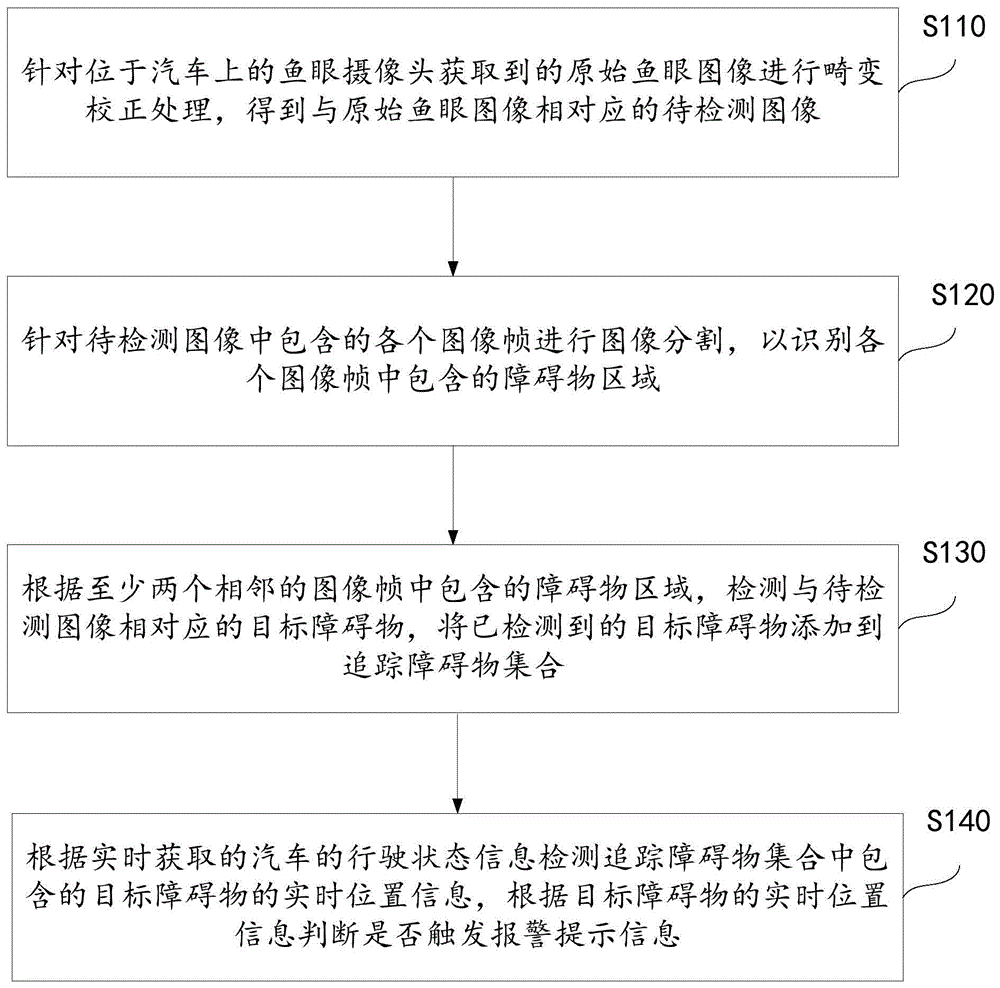
Fig. 1 shows a flowchart of an obstacle detection method based on an automobile according to an embodiment of the invention. As shown in fig. 1, the method includes:
step S110: and carrying out distortion correction processing on an original fisheye image acquired by a fisheye camera positioned on the automobile to obtain an image to be detected corresponding to the original fisheye image.
Specifically, the fisheye camera may be a front view camera installed in front of the automobile, or may be a rear view camera installed in rear of the automobile. Since the original fisheye image acquired by the fisheye camera is distorted, distortion correction processing needs to be performed, so as to obtain a corrected image to be detected.
Step S120: image segmentation is performed for each image frame contained in the image to be detected to identify obstacle regions contained in each image frame.
Specifically, image segmentation is performed on the corrected image to be detected, and the image to be detected is segmented into a plurality of areas through image segmentation processing. Generally, the image to be detected includes a plurality of areas such as a ground area, an object area located on the ground, and a background area. Correspondingly, after the background area is removed, the object area adjacent to the ground area is extracted, so that the obstacle area is identified according to the extracted object area.
Step S130: detecting a target obstacle corresponding to an image to be detected according to obstacle regions contained in at least two adjacent image frames, and adding the detected target obstacle to a tracking obstacle set.
Specifically, in order to prevent erroneous judgment due to a problem of unclear pixels or the like of a single image frame, in the present embodiment, a target obstacle corresponding to an image to be detected is detected from obstacle regions included in at least two adjacent image frames. The adjacent image frames generally contain the same obstacle, and the displacement of the obstacle in the adjacent image frames is not large, so that the reasonable displacement range of the obstacle can be verified by combining two or more adjacent image frames, whether the recognition result of the obstacle is accurate or not is assisted to be verified, and the problem of false recognition is further prevented. Correspondingly, if the target obstacle is determined by combining a plurality of image frames, the determined target obstacle is added into the obstacle tracking set so as to realize real-time obstacle tracking in the subsequent process.
Step S140: detecting real-time position information of a target obstacle contained in a tracked obstacle set according to real-time acquired running state information of the automobile, and judging whether to trigger alarm prompt information according to the real-time position information of the target obstacle.
Specifically, in the process of realizing real-time tracking of the obstacle, considering that the obstacle may temporarily disappear from the view field of the camera, in order to ensure reliable identification of the obstacle, the driving state information of the automobile is further acquired, so that the current position of the obstacle is reversely estimated according to the driving state information acquired in real time, further continuous tracking of the obstacle is realized, and whether an alarm prompt message needs to be sent or not is judged according to the tracking result, so that a driver is reminded of avoiding the obstacle.
Therefore, in the method for detecting the obstacle based on the automobile, the obstacle around the automobile can be detected by the fisheye camera, the obstacle around the automobile can be comprehensively detected due to the large detection range of the fisheye camera, and the problem of image distortion of the fisheye camera can be reduced by means of distortion correction processing and the like. In addition, the target obstacle is detected through the obstacle regions contained in at least two adjacent image frames, so that the problem of misjudgment caused by lower resolution of a single image frame can be avoided, and the accuracy of obstacle detection is improved. And the real-time position information of the target obstacle contained in the tracked obstacle set is detected by combining the real-time acquired running state information of the automobile, and the real-time position of the obstacle can be reversely pushed according to the shape state of the automobile, so that continuous tracking of the obstacle is realized when the obstacle temporarily leaves the view range of the camera, and the running safety is ensured.
Example two
Fig. 2 shows a flowchart of an obstacle detection method based on an automobile according to a second embodiment of the present invention. As shown in fig. 2, the method includes:
step S210: and carrying out distortion correction processing on an original fisheye image acquired by a fisheye camera positioned on the automobile to obtain an image to be detected corresponding to the original fisheye image.
Specifically, the fisheye camera may be a front view camera installed in front of the automobile, or may be a rear view camera installed in rear of the automobile. Since the original fisheye image acquired by the fisheye camera is distorted, distortion correction processing needs to be performed, so as to obtain a corrected image to be detected. In specific implementation, correction models based on plane projection or cylindrical projection can be used for correction, and specific implementation details are not limited by the invention.
Step S220: image segmentation is performed for each image frame contained in the image to be detected to identify obstacle regions contained in each image frame.
Specifically, image segmentation is performed on the corrected image to be detected, and the image to be detected is segmented into a plurality of areas through image segmentation processing. Generally, the image to be detected includes a plurality of areas such as a ground area, an object area located on the ground, and a background area. Correspondingly, after the background area is removed, the object area adjacent to the ground area is extracted, so that the obstacle area is identified according to the extracted object area. In specific implementation, the obstacle detection by using the image segmentation technology can separate the independent low obstacle from the ground and other backgrounds so as to obtain the drivable area of the automobile.
Step S230: and detecting a target obstacle corresponding to the image to be detected according to the obstacle regions contained in at least two adjacent image frames.
Specifically, in order to prevent erroneous judgment due to unclear pixels of a single image frame or the like, in the present embodiment, a target obstacle corresponding to an image to be detected is detected from obstacle regions included in at least two adjacent image frames. The adjacent image frames generally contain the same obstacle, and the displacement of the obstacle in the adjacent image frames is not large, so that the reasonable displacement range of the obstacle can be verified by combining two or more adjacent image frames, whether the recognition result of the obstacle is accurate or not is assisted to be verified, and the problem of false recognition is further prevented.
In the implementation, according to the obstacle region contained in the Mth image frame and the running state information of the automobile acquired in real time, predicting the obstacle prediction region contained in the M+N th image frame; determining an actual obstacle region contained in an M+N image frame, judging whether the actual obstacle region is matched with a predicted obstacle region, and detecting a target obstacle corresponding to an image to be detected according to a judging result; wherein, each image frame is ordered according to the time sequence of acquisition, and M, N is a natural number. For example, when N is equal to 1, an obstacle prediction area included in the current image frame is predicted from an obstacle area included in the previous image frame. As another example, when N is greater than 1, the obstacle prediction region included in the following image frame (abbreviated as lower frame or following frame) may be predicted in combination with the obstacle region included in the preceding image frames (abbreviated as upper frame or preceding frame). It can be seen that, when N is a natural number greater than 1, the obstacle prediction area included in the m+n-th image frame is predicted from the obstacle area included in the M-th image frame and the driving state information of the vehicle acquired in real time, specifically, the obstacle prediction area included in the m+n-th image frame is predicted from the obstacle area included in the M-th to m+n-1-th image frames and the driving state information of the vehicle acquired in real time. Accordingly, combining a plurality of previous image frames can improve accuracy of obstacle prediction.
Wherein, the actual area of the obstacle means: and detecting the image frame to be detected to obtain an obstacle region contained in the image frame. The obstacle prediction area means: the position of the obtained obstacle in the following image frame is predicted by the position of the actual area of the obstacle contained in the preceding image frame and in combination with the real-time running state information of the vehicle. It follows that, unlike the obstacle actual area, the obstacle prediction area is the position of the obstacle in the subsequent image frame predicted from the preceding image frame and the running state information of the vehicle, which is predicted by an algorithm, not actually obtained by image detection, and thus there may be an error.
Specifically, when judging whether the actual obstacle area is matched with the predicted obstacle area, and detecting a target obstacle corresponding to an image to be detected according to a judgment result, the method is realized by the following steps: firstly, extracting actual characteristic information corresponding to an actual obstacle region and predicted characteristic information corresponding to a predicted obstacle region; then, carrying out feature matching processing on the actual feature information and the predicted feature information; if the feature matching is successful, determining a target obstacle corresponding to the image to be detected according to the actual area of the obstacle. Otherwise, if the feature matching fails, prompting that the false judgment exists in the actual obstacle area or the predicted obstacle area, and needing to be verified by combining with the subsequent image frames. When the number of the current frames is multiple, the obstacle prediction areas corresponding to the previous frames are respectively matched with the obstacle actual areas of the current frames, so that a final detection result is comprehensively determined by combining multiple matching results.
Step S240: the detected target obstacle is added to the set of tracked obstacles.
Correspondingly, if the target obstacle is determined by combining a plurality of image frames, the determined target obstacle is added into the obstacle tracking set so as to realize real-time obstacle tracking in the subsequent process. Wherein an obstacle is determined as a target obstacle only when the same obstacle appears in both the obstacle prediction area determined by the preceding image frame and the obstacle actual area determined by the following image frame. It can be seen that the mutual verification can be performed by a plurality of adjacent image frames, thereby preventing erroneous recognition. The target obstacle included in the tracked obstacle set is required to be tracked continuously during traveling.
Step S250: and detecting real-time position information of the target obstacle contained in the tracked obstacle set according to the real-time acquired running state information of the automobile.
Specifically, in the process of realizing real-time tracking of the obstacle, considering that the obstacle may temporarily disappear from the view field of the camera, in order to ensure reliable identification of the obstacle, the driving state information of the automobile is further acquired, so that the current position of the obstacle is reversely estimated according to the driving state information acquired in real time, further continuous tracking of the obstacle is realized, and whether an alarm prompt message needs to be sent or not is judged according to the tracking result, so that a driver is reminded of avoiding the obstacle.
The inventor finds that continuous and low obstacles similar to road teeth or roadside fences and the like can appear in the driving process, and the obstacles are difficult to effectively detect in a common detection scheme because of low height and continuous length. In order to solve the above-described problem, in the present embodiment, identification features are set in advance for such continuous and low obstacles, and a preset height threshold value and a length threshold value are specifically defined so as to quickly and accurately determine such obstacles. In particular, when the detected target obstacle is lower than the preset height threshold and the length is greater than the preset length threshold, the target obstacle is determined to be a continuous obstacle. Accordingly, the undetected portion contained in the continuity obstacle can be predicted from the detected portion contained in the continuity obstacle, depending on the shape characteristics of the continuity obstacle. For example, since an obstacle such as a curb or a fence has a fixed height and a length extending in the road direction, the height, length, shape, and the like of an undetected portion included in a continuity obstacle can be predicted from the characteristics such as the height, length, shape, and the like of the detected portion included in the continuity obstacle, and further, an obstacle region that may continuously appear around the vehicle can be predicted in advance before the undetected portion enters the detection range of the camera. In specific prediction, a continuous obstacle prediction model may be preset, and accordingly, feature information such as a height, a length, a shape, and the like of a detected portion included in the continuous obstacle obtained in real time is input into the continuous obstacle prediction model, so that content such as a height, a length, a shape, and the like of an undetected portion included in the continuous obstacle is predicted according to a model output result. The continuous obstacle prediction model can be trained by means of machine learning and the like. Therefore, according to the characteristic that the continuous short obstacles are arranged continuously along the road direction, the continuous obstacles which do not enter the visual field of the automobile can be predicted in advance, and risks can be avoided conveniently. Accordingly, when real-time position information of the target obstacle contained in the tracked obstacle set is detected according to the real-time acquired driving state information of the automobile, if the target obstacle is not contained in the current image frame, the current position of the undetected portion contained in the target obstacle is predicted according to the real-time acquired driving state information of the automobile. For example, the current position of the undetected portion included in the target obstacle can be predicted from information such as the running speed of the automobile and the steering wheel rotation speed. In this embodiment, the fisheye camera located on the automobile is typically a front view fisheye camera located in front of the automobile to facilitate early detection of an obstacle before the vehicle collides with the obstacle. Of course, during the reverse of the vehicle, the detection can also be performed by a rearview fish-eye camera positioned at the rear of the vehicle.
Step S260: and judging whether to trigger alarm prompt information according to the real-time position information of the target obstacle.
Specifically, when the real-time position information of the target obstacle is judged to be close to the vehicle, the alarm prompt information is triggered to remind the driver of avoiding the obstacle. The alarm prompt information can be various types such as voice prompt information, steering wheel vibration information and the like, and the invention is not limited to the voice prompt information.
For easy understanding, the following details of implementation of the second embodiment of the present invention are described in detail by taking a specific example as an example:
first, for easy understanding, the technical background of this example is briefly described: in order to achieve intelligent driving, detection and tracking of obstacles outside the vehicle are required. Currently, there are many solutions for detecting external obstacles (such as isolation posts, people, vehicles, etc.), and there are many difficulties for detecting short, continuous obstacles (such as road teeth, etc.). Existing algorithms for off-board obstacle detection include radar-based and forward-looking camera-based solutions or a combination of both, often requiring a combination of radar and vision sensors for continuous obstacle detection. The radar-based detection technology has limited visual field range, single sensors have blind areas, and the development difficulty of software and hardware for multi-sensor fusion is high. In addition, the field of view scope of fish-eye camera is big, and the fish-eye camera of front, left, back, right installation can cover 360 degrees fields of view around the car, and can observe the barrier that the nearly car department of low department appears. However, the distortion of the fisheye camera increases a great difficulty in detecting the obstacle, and missed detection and false detection often exist; on the other hand, when using four-way fisheye cameras, the pictures acquired by the four cameras every second occupy most of the bandwidth and computing resources of the intelligent system on the vehicle, so that the real-time detection is difficult to ensure.
In order to solve the above-mentioned problems, the present example proposes a method for detecting and tracking a short obstacle according to a vehicle motion state and a fisheye camera in front of a vehicle, and aims to overcome the following technical problems in the existing vehicle-mounted visual obstacle detection scheme: the problem that a common forward-looking camera cannot detect short obstacles near the vehicle; the contour and the position of the continuous low obstacle are difficult to detect by a visual method; the four-way fisheye camera signal occupies too high bandwidth and computational resources, but the single camera has limited visual field. This example can solve the above-described problem, detect an independent/continuous low obstacle outside the vehicle by a front-view fisheye camera, and alarm against an obstacle coming into the alert range. This example mainly includes: distortion correction, obstacle detection based on image segmentation, obstacle world coordinate calculation, previous frame information fusion, obstacle tracking, obstacle alarming, display and other processes. First, distortion correction is performed on a fisheye image, and pixel segmentation is performed on the corrected image to obtain an image contour of an obstacle. And calculating the position of the obstacle on the ground according to the contour line of the obstacle contacted with the ground pixels. And combining the detection result of the previous frame to optimize the detection result of the current frame. When the obstacle leaves the field of view of the forward-looking fisheye camera, the obstacle is continuously tracked by utilizing the vehicle motion information. And if the nearest distance from the obstacle to the vehicle or the running track line is smaller than the preset guard distance, giving an alarm and displaying to the user. Specifically, the present example proposes a method for detecting and tracking a low-level obstacle based on a forward-looking fisheye camera during low-speed driving, and the detection of the low-level obstacle is completed by means of a deep learning image segmentation technique, so that especially a continuous low-level obstacle which is difficult to detect in the conventional obstacle detection process can be detected, and a more reliable detection result can be provided through front-back frame information fusion. In addition, the example can be realized by only using a front-view fisheye camera and matching with vehicle motion information acquisition, has low hardware cost, and has real-time performance compared with a visual detection system based on four paths of fisheyes.
In particular, the present example may be implemented by an intelligent system in a vehicle, which is further divided into a plurality of modules such as distortion correction, obstacle detection based on image segmentation, obstacle world coordinate calculation, previous frame information fusion, obstacle tracking, and obstacle warning and display. The following detailed description is made with respect to specific implementation principles of each module:
(1) And a distortion correction module: the fisheye image I is acquired by a forward looking fisheye camera. In order to make the image segmentation effect enough to perform feature extraction, the scheme firstly performs distortion correction on the acquired fisheye image. The scheme can adopt a correction model based on plane projection or cylindrical projection, wherein the correction model can better eliminate radial distortion of the fisheye camera, and the correction model can keep the image of the fisheye center position in original horizontal and vertical forms. With the correction model MR described above, a corrected image IR can be obtained.
(2) Obstacle detection module based on image segmentation: the scheme trains the image segmentation model M based on deep learning s The obstacle detection by using the image segmentation technology can separate the independent low obstacle from the ground and other backgrounds to obtain the drivable area, and can solve the problem that the traditional scheme can not identify the continuous low obstacle. For the ith frame image I R i Edge extraction is carried out on the segmented obstacle to obtain the outline C of the obstacle i Contour line C of contact with the ground G i The latter can be used for subsequent distance calculation and previous frame information fusion.
(3) Obstacle world coordinate calculation module: obstacle ground contact contour line C acquired by combining obstacle detection module G i Image distortion correction model M R And camera calibration parameters H, the ground contour line C of the obstacle is calculated G i Projected onto the ground and calculated to obtain the world coordinate L of the obstacle ground outline i . All detected obstacles form a set { L ] i }。
(4) And a previous frame information fusion module. In order to ensure the real-time performance of detection, a smaller resolution image may be used for detection, so that the outline of the obstacle detected each time may be incomplete or inaccurate, and meanwhile, a condition of detection omission and false detection may exist. The scheme optimizes the detection result by adopting a mode of fusion of the previous frame information, so that the detected outline and position of the obstacle are more reliable. The previous frame information fusion step is shown in fig. 6, and specifically includes the following steps:
firstly, the obstacle ground coordinate set { L ] of the last frame calculated in the obstacle world coordinate calculation module is utilized
i-l Predicting the position L of the obstacle contour line in the next frame by combining the vehicle motion information (acquiring the wheel speed and steering information by the vehicle OBD)
P i And form a prediction set
Calculating the detection result of the frame to obtain a set { L } of the contour coordinates of the obstacle in the frame
i }。
Then, for { L ]
i Each of the present frame detection results L
i Traversing the obstacle prediction set of the previous frame
Is predicted for each of the obstacle positions L
P i . If there are single or multiple predicted obstacles L that satisfy feature matching (which can be simply matched by distance or IOU)
P i Confirm that the current frame detects obstacle L
i Non-false detection, will L
i And L
P i Is weighted and fused from +.>
Delete predicted obstacle L
P Will L
i Adding a set { T } of obstacles to be tracked; if the predicted obstacle meeting the feature matching is not met, the detected obstacle L
i Tentatively as a false detection obstacle, if the number of times of non-matching exceeds a preset threshold value, confirming L
i For false detection, it is derived from { L }
i Delete in }. By blocking the preceding frameThe obstacle prediction result and the coordinates of the obstacle detection result of the frame are subjected to weighted fusion, so that the problem of inaccurate identification caused by low resolution can be solved, and the detection accuracy of the obstacle can be improved by combining a plurality of image frames.
(5) Obstacle tracking module: for { L i And (3) when the obstacle leaves the field of view of the front-view fisheye camera, calculating the ground displacement of the obstacle reversely by using the vehicle motion information so as to track the obstacle.
(6) Obstacle alarm and display module: and calculating a vehicle running track line through vehicle motion information, then calculating the nearest distance between the obstacle and the vehicle or the track line, and if the nearest distance is smaller than a preset guard distance, projecting the obstacle to a specific display plane through perspective transformation, and displaying the obstacle to a user on a vehicle.
In order to facilitate understanding of the above-described process, fig. 5 shows a flow chart of an obstacle tracking method in the present example, in which, as shown in fig. 5, on the one hand, coordinates of an obstacle are acquired by a fisheye image; on the other hand, the vehicle motion state is acquired through the information such as the rotation speed or the steering of the wheels, and thus the obstacle tracking is realized by combining the vehicle motion state, the vehicle running track and the obstacle coordinate information. Fig. 6 is a schematic flow chart showing the fusion of the previous frame information, and as shown in fig. 6, feature matching is performed according to the detected obstacle of the present frame and the predicted obstacles of the plurality of previous frames, so that the target obstacle is determined according to the feature matching result. Because the number of the upper frames is multiple, the predicted obstacle of each upper frame and the detected obstacle of the present frame can be respectively matched, so that multiple matching results corresponding to each upper frame (also called a previous frame or a previous image frame) are obtained, and whether the target obstacle is finally determined according to the matching times. For example, if the number of times of non-matching reaches a preset threshold, the obstacle is confirmed to be false.
In summary, according to the embodiment of the invention, the detection can be performed by the fisheye camera, and the detection range of the fisheye camera is large, so that the obstacle around the vehicle can be comprehensively detected, and the problem of image distortion of the fisheye camera can be reduced by means of distortion correction processing and the like. In addition, the target obstacle is detected through the obstacle regions contained in at least two adjacent image frames, so that the problem of misjudgment caused by lower resolution of a single image frame can be avoided, and the accuracy of obstacle detection is improved. And the real-time position information of the target obstacle contained in the tracked obstacle set is detected by combining the real-time acquired running state information of the automobile, and the real-time position of the obstacle can be reversely pushed according to the shape state of the automobile, so that continuous tracking of the obstacle is realized when the obstacle temporarily leaves the view range of the camera, and the running safety is ensured. And whether the obstacle detected by the frame is correct or not is comprehensively judged by combining the prediction results of a plurality of upper frames, so that the detection accuracy can be remarkably improved.
Example III
Fig. 3 shows a schematic structural diagram of an obstacle detection device based on an automobile according to a third embodiment of the present invention, which specifically includes:
The correction module 31 is adapted to perform distortion correction processing on an original fisheye image acquired by a fisheye camera positioned on an automobile to obtain an image to be detected corresponding to the original fisheye image;
a segmentation module 32 adapted to perform image segmentation for each image frame contained in the image to be detected to identify an obstacle region contained in each image frame;
a detection module 33 adapted to detect a target obstacle corresponding to the image to be detected from obstacle regions contained in at least two adjacent image frames, adding the detected target obstacle to a set of tracked obstacles;
the tracking module 34 is adapted to detect real-time position information of a target obstacle included in the tracked obstacle set according to real-time acquired driving state information of the vehicle, and determine whether to trigger alarm prompt information according to the real-time position information of the target obstacle.
Optionally, the detection module is specifically adapted to:
predicting an obstacle prediction area contained in the M+N image frames according to the obstacle area contained in the M image frames and the running state information of the automobile acquired in real time;
determining an obstacle actual area contained in an M+N image frame, judging whether the obstacle actual area is matched with the obstacle prediction area, and detecting a target obstacle corresponding to the image to be detected according to a judging result; wherein M, N is a natural number.
Optionally, the detection module is specifically adapted to:
extracting actual characteristic information corresponding to the obstacle actual region and predicted characteristic information corresponding to the obstacle predicted region;
performing feature matching processing on the actual feature information and the predicted feature information;
and if the feature matching is successful, determining a target obstacle corresponding to the image to be detected according to the actual obstacle area.
Optionally, when N is a natural number greater than 1, the detection module is specifically adapted to:
and predicting an obstacle prediction area contained in the M+N image frames according to the obstacle areas contained in the M image frames to the M+N-1 image frames and the running state information of the automobile acquired in real time.
Optionally, when the height of the target obstacle is lower than a preset height threshold value and the length is greater than a preset length threshold value, determining that the target obstacle is a continuous obstacle; wherein the undetected portion contained in the continuity barrier can be predicted from the detected portion contained in the continuity barrier.
Optionally, the tracking module is specifically adapted to:
and if the current image frame does not contain the target obstacle, predicting the current position of an undetected part contained in the target obstacle according to the running state information of the automobile acquired in real time.
Optionally, the fisheye camera on the automobile is a front view fisheye camera.
The specific implementation principle of each module may refer to the description of the corresponding part in the method embodiment, which is not repeated here.
Example IV
A fourth embodiment of the present application provides a non-volatile computer storage medium storing at least one executable instruction that can perform the method for detecting an obstacle based on an automobile in any of the above method embodiments. The executable instructions may be particularly useful for causing a processor to perform the operations corresponding to the method embodiments described above.
Example five
Fig. 4 shows a schematic structural diagram of an electronic device according to a fifth embodiment of the present invention, and the specific embodiment of the present invention is not limited to the specific implementation of the electronic device.
As shown in fig. 4, the electronic device may include: a processor 402, a communication interface (Communications Interface) 406, a memory 404, and a communication bus 408.
Wherein:
processor 402, communication interface 406, and memory 404 communicate with each other via communication bus 408.
A communication interface 406 for communicating with network elements of other devices, such as clients or other servers.
The processor 402 is configured to execute the program 410, and may specifically perform relevant steps in the above-described embodiment of the method for detecting an obstacle based on an automobile.
In particular, program 410 may include program code including computer-operating instructions.
The processor 402 may be a central processing unit CPU, or an Application specific integrated circuit ASIC (if ic Integrated Circuit), or one or more integrated circuits configured to implement embodiments of the present invention. The one or more processors included in the electronic device may be the same type of processor, such as one or more CPUs; but may also be different types of processors such as one or more CPUs and one or more ASICs.
Memory 404 for storing program 410. Memory 404 may comprise high-speed RAM memory or may further comprise non-volatile memory (non-volatile memory), such as at least one disk memory.
The program 510 may be specifically configured to cause the processor 502 to perform the respective operations corresponding to the above-described method embodiments.
The algorithms and displays presented herein are not inherently related to any particular computer, virtual system, or other apparatus. Various general-purpose systems may also be used with the teachings herein. The required structure for a construction of such a system is apparent from the description above. In addition, the present invention is not directed to any particular programming language. It will be appreciated that the teachings of the present invention described herein may be implemented in a variety of programming languages, and the above description of specific languages is provided for disclosure of enablement and best mode of the present invention.
In the description provided herein, numerous specific details are set forth. However, it is understood that embodiments of the invention may be practiced without these specific details. In some instances, well-known methods, structures and techniques have not been shown in detail in order not to obscure an understanding of this description.
Similarly, it should be appreciated that in the foregoing description of exemplary embodiments of the invention, various features of the invention are sometimes grouped together in a single embodiment, figure, or description thereof for the purpose of streamlining the disclosure and aiding in the understanding of one or more of the various inventive aspects. However, the disclosed method should not be construed as reflecting the intention that: i.e., the claimed invention requires more features than are expressly recited in each claim. Rather, as the following claims reflect, inventive aspects lie in all features of a single foregoing disclosed embodiment. Thus, the claims following the detailed description are hereby expressly incorporated into this detailed description, with each claim standing on its own as a separate embodiment of this invention.
Those skilled in the art will appreciate that the modules in the apparatus of the embodiments may be adaptively changed and disposed in one or more apparatuses different from the embodiments. The modules or units or components of the embodiments may be combined into one module or unit or component and, furthermore, they may be divided into a plurality of sub-modules or sub-units or sub-components. Any combination of all features disclosed in this specification (including any accompanying claims, abstract and drawings), and all of the processes or units of any method or apparatus so disclosed, may be used in combination, except insofar as at least some of such features and/or processes or units are mutually exclusive. Each feature disclosed in this specification (including any accompanying claims, abstract and drawings), may be replaced by alternative features serving the same, equivalent or similar purpose, unless expressly stated otherwise.
Furthermore, those skilled in the art will appreciate that while some embodiments described herein include some features but not others included in other embodiments, combinations of features of different embodiments are meant to be within the scope of the invention and form different embodiments. For example, in the following claims, any of the claimed embodiments can be used in any combination.
Various component embodiments of the invention may be implemented in hardware, or in software modules running on one or more processors, or in a combination thereof. Those skilled in the art will appreciate that some or all of the functions of some or all of the components in accordance with embodiments of the present invention may be implemented in practice using a microprocessor or Digital Signal Processor (DSP). The present invention can also be implemented as an apparatus or device program (e.g., a computer program and a computer program product) for performing a portion or all of the methods described herein. Such a program embodying the present invention may be stored on a computer readable medium, or may have the form of one or more signals. Such signals may be downloaded from an internet website, provided on a carrier signal, or provided in any other form.
It should be noted that the above-mentioned embodiments illustrate rather than limit the invention, and that those skilled in the art will be able to design alternative embodiments without departing from the scope of the appended claims. In the claims, any reference signs placed between parentheses shall not be construed as limiting the claim. The word "comprising" does not exclude the presence of elements or steps not listed in a claim. The word "a" or "an" preceding an element does not exclude the presence of a plurality of such elements. The invention may be implemented by means of hardware comprising several distinct elements, and by means of a suitably programmed computer. In the unit claims enumerating several means, several of these means may be embodied by one and the same item of hardware. The use of the words first, second, third, etc. do not denote any order. These words may be interpreted as names.