CN1123189C - Hinge mechanism - Google Patents
Hinge mechanism Download PDFInfo
- Publication number
- CN1123189C CN1123189C CN97197488A CN97197488A CN1123189C CN 1123189 C CN1123189 C CN 1123189C CN 97197488 A CN97197488 A CN 97197488A CN 97197488 A CN97197488 A CN 97197488A CN 1123189 C CN1123189 C CN 1123189C
- Authority
- CN
- China
- Prior art keywords
- articulated elements
- linkwork
- communicator
- transaudient
- mentioned
- Prior art date
- Legal status (The legal status is an assumption and is not a legal conclusion. Google has not performed a legal analysis and makes no representation as to the accuracy of the status listed.)
- Expired - Fee Related
Links
Images


Classifications
-
- H—ELECTRICITY
- H04—ELECTRIC COMMUNICATION TECHNIQUE
- H04M—TELEPHONIC COMMUNICATION
- H04M1/00—Substation equipment, e.g. for use by subscribers
- H04M1/02—Constructional features of telephone sets
- H04M1/0202—Portable telephone sets, e.g. cordless phones, mobile phones or bar type handsets
- H04M1/0206—Portable telephones comprising a plurality of mechanically joined movable body parts, e.g. hinged housings
- H04M1/0208—Portable telephones comprising a plurality of mechanically joined movable body parts, e.g. hinged housings characterized by the relative motions of the body parts
- H04M1/0214—Foldable telephones, i.e. with body parts pivoting to an open position around an axis parallel to the plane they define in closed position
- H04M1/0216—Foldable in one direction, i.e. using a one degree of freedom hinge
-
- H—ELECTRICITY
- H04—ELECTRIC COMMUNICATION TECHNIQUE
- H04M—TELEPHONIC COMMUNICATION
- H04M1/00—Substation equipment, e.g. for use by subscribers
- H04M1/02—Constructional features of telephone sets
- H04M1/03—Constructional features of telephone transmitters or receivers, e.g. telephone hand-sets
- H04M1/035—Improving the acoustic characteristics by means of constructional features of the housing, e.g. ribs, walls, resonating chambers or cavities
Abstract
The present invention relates to a hinge mechanism which provides a tight sound guide joint in a sound guide (13) which is split between a communication unit (11) and a foldable flip part (12). At least two shaft elements (21, 22) pivotally connect the flip part to the communication unit. Each shaft element is arranged in a respective pivot point (26, 27) for the flip part along the pivot axis (25) of the flip part. The sound guide joint is arranged in a first pivot point (26) for the flip part between an opposing surface on the flip part and an opposing surface on the communication unit. The sound guide parts (13a, 13b) are thereby connected to each other irrespective of which pivot position the flip part takes up relative to the communication unit. The hinge mechanism comprises at least one compressive resilient element (32), which, via a shaft element (22) in a second pivot point (27), exerts a force on the two opposing surfaces so that the sound guide joint is pressed together and becomes sound-tight.
Description
Technical field
The present invention relates to the linkwork of hand-hold communication device (for example mobile phone) with flype.More precisely, the present invention relates to possess can be transaudient but the linkwork of soundtight transaudient assembly junction, and transaudient assembly is then respectively on this flype and this communication device.
Technical situation
In the wireless telephonic technical field of exploitation, main trend is that communicator is more and more littler.Minimum at present communicator, its length is less than the distance between ear and the mouth.So send words ends can not be fully near mouth to obtain the good sound quality.Also be received from interfering noise on every side.So so little communicator can install can from communicator send that words ends opens renovate (being that so-called passive type is renovated) to receive speech.
In order to obtain sound quality preferably, collapsible renovating can have transaudient of air flue type that the sound that receives is reached microphone in the communicator fuselage.Such foldable lid is called semi-movable and renovates.Usually make with rigid material for transaudient, therefore transaudient assembly must by renovate with the communicator fuselage on two transaudient combine.Transaudient assembly has been arranged, just can pull down if desired renovating from the communicator fuselage.
The communicator that also has in order to make microphone more near mouth, thoroughly is placed on microphone and renovates, promptly so-called movable renovating.The shortcoming of this communication apparatus structure is that susceptibility that disturbs and vulnerability of structure are increased.More complicated with movable communication apparatus structure of renovating even manufacturing, so price is higher.
The communicator renovated of band semi-movable has transaudient assembly, for will from around interference sound not reach microphone, and for speech is unnecessarily passed from transaudient assembly, it is important making transaudient combination of components place sound-proof.
The communication device (for example mobile phone) that patent application SE9601701-7 describes has semi-movable to be renovated, and its designed transaudient be a single-piece, and transaudient by renovating and passing through the microphone of communicator fuselage in the communicator fuselage.Make with certain flexible material for this transaudient, for example silicon, fabric or cloth.Owing to make with single-piece for transaudient, just do not have the junction that noise can import into or speech can appear.Therefore, this to renovate be non-removable.
With the linkwork that the collapsible communicator of renovating has certain form, this linkwork will be renovated and be connected on the communicator, make to renovate with respect to the communicator fuselage and can pivot.
Typical linkwork is formed by three at least, and wherein two articulated elementss are on this device part wherein, and an articulated elements is on another part of this device.The jointed shaft of certain form runs through each articulated elements, thereby makes two parts of this device relative to each other to rotate with the jointed shaft as pivot.
On the communicator that the band semi-movable is renovated, preferably renovate and to be positioned at special opening stop position and close up stop position.When renovating between two stop positions, also preferably renovate and attempt to be positioned at stop position, therefore renovating towards the motion of stop position will be steadily uniformly.
The linkwork that United States Patent (USP) 5274882 is described, it makes articulated elements relative to each other remain on preposition.Its designed articulated elements has the convex concave connector, between two articulated elementss spring is arranged, and spring is pressed to the spill connector with the convex connector.Be positioned at when opening the position when renovating, the convex concave connector is connected to each other.
What European patent application EP 0275996B1 described is the communicator that the band semi-movable is renovated.Microphone is contained in the communicator fuselage near the linkwork place.Renovate transaudient will reach microphone from the sound of renovating transaudient in the communicator fuselage.Transaudient junction is between the shell and communicator fuselage of linkwork.Be in maximumly when opening the position when renovating, the aperture between transaudient in renovate transaudient and the communicator fuselage makes two transaudient to be connected to each other directly.Can use encapsulant to make the unlikely microphone that enters of interference sound around transaudient junction.
The shortcoming of this kind structure be have only when renovate be in renovate when maximum is opened the position transaudient could with the communicator fuselage in transaudient be connected.Shift out this position if renovate, transaudient just no longer includes any connection.
Summary of the present invention
A problem that the present invention relates to is how to design linkwork and make transaudient assembly joint portion and ambient noise isolate the communicator that this linkwork connecting band semi-movable is renovated.
Another problem that the present invention relates to is, how to make to renovate and make it and send the words position to be in special stop position, and should how when stop position changes flip position, the different piece of transaudient assembly be contacted with each other from start to finish the user in closed position.Another problem that the present invention relates to is how to design linkwork and make and can pull down also and can reset renovating to install once more renovating from communicator at an easy rate.
Another problem that the present invention relates to is that linkwork should be made and be contained in easily communicator easily and renovate, and makes cost effectiveness better.
Therefore, an object of the present invention is to design and connect the linkwork that communicator and collapsible semi-movable are renovated, make renovate and communicator between transaudient combination of components place and isolates sound on every side.
Another object of the present invention is that to renovate should be can install with dismountable, renovate to be in and close up and open position, motion between these two positions should be stably, no matter renovates which kind of position that is in the rotation simultaneously, and the different piece of transaudient assembly all should contact with each other.
Another purpose of the present invention is that linkwork should be made and install simply, make cost effectiveness better, and linkwork should satisfy long-term quality requirement.
The problems referred to above are resolved by making transaudient combination of components portion be positioned at the fulcrum place of renovating on communicator, and this communicator is the communicator of renovating with collapsible.Linkwork comprises two axle spares at least, and the axle part will be renovated and be pivotally connected on the communicator.At least axle one of part is exerted pressure to transaudient assembly joint portion, thereby transaudient assembly joint portion forced together and makes it sound-proof.
In more detail, the problems referred to above are resolved by making transaudient combination of components portion be positioned at first fulcrum place of renovating, and this fulcrum is between a surface of surface of renovating and communicator, and these two surfaces are the apparent surface.Therefore no matter renovate to pivot and be in which kind of position and all make two transaudient to be connected to each other together with respect to communicator.Renovate with respect to communicator and rotate around two fulcrums at least, fulcrum is positioned at the direction along pivot.At least locate at one of two fulcrums, the axle part be positioned on the articulated elements and the relative articulated elements of packing on corresponding recesses, make to renovate to be pivotally connected on the communicator.At least one of axle part is subjected to the influence of pivot direction elastic pressure.This part can itself be made compressible elastomeric spare (for example rubber parts), or this part is subjected to the influence of elastic component (for example mechanical spring) directly or indirectly.For example, this part can move vertically and be positioned at and renovate or the articulated elements of communicator.This part can contact with compressible elastomeric spare then, and this compressible elastomeric spare is exerted pressure towards this part in the pivot direction.The influence that elastic pressure applies this part makes this part exert pressure to one of apparent surface again.One of this apparent surface is pressed to another apparent surface then again.No matter renovate to pivot and be in which kind of position, all can obtain soundtight transaudient assembly junction with respect to communicator.
An advantage of the invention is that transaudient combination of components is in renovates when pivoting with respect to communicator sound-proofly, no matter renovates to pivot with respect to communicator and is in which kind of position.Linkwork design of the present invention also can be pulled down renovating from communicator.
Another advantage of the present invention is that linkwork of the present invention is made easily and installed, so cost effectiveness is good.
By means of preferred embodiment and referring to accompanying drawing the present invention is described more carefully now.
The description of accompanying drawing
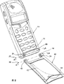
Two perspective views of communicator of being with semi-movable to renovate that are illustrated in figures 1 and 2.It comprises three-member type linkwork of the present invention, renovates among the figure with the communication means fuselage and separates;
Figure 3 shows that the cross-sectional view of three-member type linkwork of the present invention, renovate and be in the position of opening;
Figure 4 shows that pack into perspective view before the communicator of helical spring of the present invention and latch;
Figure 5 shows that the cross-sectional view of three-member type linkwork embodiment of the present invention;
Figure 6 shows that the cross-sectional view of another embodiment of three-member type linkwork of the present invention;
Figure 7 shows that the cross-sectional view of five formula linkworks of the present invention embodiment;
Figure 8 shows that the cross-sectional view of another embodiment of five formula linkworks of the present invention.
Preferred embodiment
Illustrated in figures 1 and 2 is the perspective view of two different directions of the embodiment of the invention, and this communicator 11 is mobile communication means.This communicator has a folding so-called semi-movable to renovate.Transaudient assembly will reach microphone (see figure 3) in the communicator in the open mode of renovating from the sound of sound input component 14 by means of first transaudient 13a and second transaudient 13b.Pull down semi-movable from communicator as depicted in figs. 1 and 2 and renovate 12, the one end has two bossings that form first outer articulated elements 15 and second outer articulated elements 16 (relative with first articulated elements).Interior articulated elements 17 is formed on the bottom of communicator.Should in articulated elements can pack between first outer articulated elements 15 and second the outer articulated elements 16.
Figure 3 shows that the cross-sectional view of linkwork of the present invention, look like facing the front then vertically it being sectioned of communicator.Figure middle section with dashed lines A-A represents.Renovate among the figure and be in the predetermined position of opening.The fixed shaft of first protrusion is arranged in first end 19 of interior articulated elements, and it is a cylinder pivot pin 21, has second movably to protrude the axle part in second end 20 of interior articulated elements, and it is a latch 22.Two axle spares 21 and 22 can not rotate with respect to interior articulated elements 17, but latch 22 can move axially at it.
On first and second outer articulated elements 15 and 16 depression 23 and 24 are arranged respectively, first and second are protruded a part and are respectively charged in depression 23 and 24.Therefore, first can rotate with respect to interior articulated elements around pivotal line 25 with second outer articulated elements 15 and 16, pivotal line 25 passes three articulated elementss 15,16 and 17, by two axle spares 21 and 22, can make and renovate 12 and not only can open but also can close up on communicator 11 from communicator 11.
At fulcrum 26 places of renovating 12, pivotal line 25 intersects with the bottom surface of the depression 23 of first outer articulated elements, and at another fulcrum 27 places, intersect the bottom surface of the depression 24 of pivotal line 25 and second outer articulated elements.
Transaudient 13 will be from the sound of tut input component 14 by renovating the microphone 28 that imports in the communicator.Transaudient 13 is assemblies, is made up of first transaudient the 13a in renovating and second transaudient 13b in the communicator.The above-mentioned pivot pin 21 that the direction of articulated elements 15 is protruded outside first is connected rigidly with first end 19 of interior articulated elements in this case.On the direction of pivotal line, second transaudient 13b begins in the end face of pivot pin 21.For ambient noise is kept off outside, second transaudient among this embodiment is included in the rubber parts 29.The shape of the depression 23 of first outer articulated elements 15 matches with the shape of pivot pin 21, and at the fulcrum of renovating, first transaudient 13a opens wide in the bottom surface of depression 23.The end face of the bottom surface of depression 23 and pivot pin 21 forms two surfaces respect to one another.
Therefore, between the bottom surface of the depression 23 of transaudient assembly binding site articulated elements 15 outside first and the end face of pivot pin 21, fulcrum 26 places of promptly renovating.Rotate with respect to communicator around pivotal line 25 no matter how renovate, two transaudient 13a and 13b can be connected to each other.
On the direction of pivotal line, second end 20 of interior articulated elements 17 has individual hole 30, can enter cavity 31 from this hole.In this cavity, an end of the elastic component 32 (being a mechanical coil spring in the present embodiment) that is positioned on the pivot direction is contacted with the end face of cavity 31.In above-mentioned latch 22 segment insertion holes 30, thereby an end 33 of this latch is stretching out hole 30 and articulated elements 16 outside second on the pivotal line direction.The extension of this latch forms second axle spare.On the pivotal line direction, the other end 34 of this latch forms the pin that stretches out that inserts in the helical spring 32.
Articulated elements 17 in latch 22 shifts out on the pivotal line direction when rotating in order to prevent to renovate, and prevent that latch 22 from rotating with respect to interior articulated elements, has individual latch hook 35 on this latch.Figure 4 shows that the perspective view before latch 22 and spring 32 insert interior hinged member bore 30.Latch hook 35 stretches out to pin 34 directions of stretching out of latch 22, ends to protrude latch hook point 36.With latch hook 35 patchholes 30 time, its otch 37 to latch 22 can be depressed.Fluted 38 on the hole 30, the latch hook 35 of latch 22 this groove of can packing into.Like this, this latch just can not pivot with respect to interior hinge element after latch hook has been packed groove into.
As shown in Figure 3, the cavity 31 on the interior articulated elements is wideer than hole 30, so 30 enter cavity 31 individual edge 39 is arranged from the hole.When latch hook 35 being inserted to such an extent that enough far make the latch hook point in cavity, this latch hook outwards ejects from latch 22.If latch 22 articulated elements direction outside second moves enough far, latch hook point 36 can be hooked on the edge 39 so.Like this, just can prevent to shift out interior articulated elements fully after latch 22 from having inserted interior articulated elements.Like this, with regard to being easy to and with spring 32 and the latch 22 interior articulated elements of packing into by spring 32 and latch 22 are pressed into cavity 31 from the outside.
When with latch 22 patchholes 30 and renovate when being contained on the communicator, spring 32 contacts with latch 22.Like this, the direction of spring 32 articulated elements 16 outside second applies power on latch 22.Therefore, latch 22 applies power with the 16 pivotal line directions of pushing to away from second end 20 of interior articulated elements on the articulated elements 16 outside second.This means whole renovate 12 outside with second the identical direction pressurized of articulated elements 16, therefore first outer articulated elements 15 is pushed to the direction of interior first end 19 of articulated elements.Then, the pivot pin 21 of interior articulated elements 17 is pressed to the bottom surface in the hole 23 of first outer articulated elements 15, thereby two apparent surfaces of transaudient assembly junction are forced together makes that transaudient assembly junction is sound-proof.Be in any pivot location because no matter at the fulcrum place, renovate with respect to communicator transaudient assembly junction, transaudient assembly junction all is soundtight.
In the present embodiment, the protruding end of latch 22 is a V-arrangement, and there is individual v-depression in the hole 24 of second outer articulated elements 16.The V-arrangement end of latch 22 and the v-depression in hole 24 form so-called convex concave connector.This V-arrangement end occupies first and second position, these two positions be separated by 180 ° can with v-depression centering.Only allow to renovate and pivot 180 °.Preventing the continuous motion of renovating, is to contact communicator by the upper end of renovating in closed position on the one hand, is on the other hand to contact the communicator lower end by renovating when closed position is opened about 180 °.Like this, when renovating when it opens the position, can only make above-mentioned V-arrangement end first position and above-mentioned v-depression centering.By pressure, renovate to move to from closed position and open the position from user's hand.
When the V-arrangement end in two centering positions during more near one of them, it attempts to realize centering.When renovating when closing up, it more approaches second position of V-arrangement end and v-depression centering.Renovate with regard to prevention like this and be in the position that needs and renovate and attempt to arrive this position, be fixed on the appropriate location that contacts with communicator so renovate.Attempt voluntarily the V-arrangement end and v-depression centering makes to renovate opening between position and the closed position reposefully and moves.
The present invention is in order to realize that the convex concave connector is used in motion stably between many stop positions, and relevant this more detailed description is seen above-mentioned US Patent specification No. 5274882.Obviously as can be known, the shape of convex concave connector can be different, for example U-shaped from above-mentioned patent document.More if desired stop position, the spill connector, promptly the depression on second articulated elements can comprise several grooves.The shape of convex connector is not must be corresponding with the shape of spill connector.U-shaped point in the v-depression also can be realized pivoting corresponding to accurate stop position.
When articulated elements 16 pushed latch 22 outside second to by spring 32, outside second end 20 of interior articulated elements and second, form space 40 between the articulated elements 16.If second outer articulated elements bears enough pressure, for example in user's hand, can space 40 is compressed together, so that the compression spring.When space 40 is compressed in a time-out, first outer articulated elements 15 can be pivoted from pivot pin 21 to unload, second outer articulated elements 16 can be drawn back from the V-arrangement end 33 of latch 22 afterwards.Like this, can pull down from communicator 11 renovating 12.
Therefore, this can be renovated and change another into and renovate, for example another kind of outward appearance renovates.At first, by second outer articulated elements 16 is through on the latch 22, afterwards this latch is pressed to spring 32 so that compression space 40 is fixed on the communicator newly renovating.After this, first outer articulated elements 15 is rotated around pivot pin 21.
Figure 5 shows that another embodiment of three-member type linkwork of the present invention, it has first and second outer articulated elements and an interior articulated elements, the fulcrum place that is renovating transaudient assembly junction.Identical reference numerals part was used in Fig. 3.As previous embodiment, two outer articulated elementss 15 and 16 are being renovated on 12, and interior articulated elements is on communicator 11.First fixed shaft 51, its end face is a V-arrangement, from first end 19 of interior articulated elements 17 stretch out and this with outside articulated elements be connected.First part V-arrangement hole 52 on first outer articulated elements 15 of packing into.Transaudient assembly junction is at first fulcrum place of renovating 26, and between the bottom surface in the end face of first part 51 and hole 52, these two surfaces form surfaces opposite to each other.From renovating the bottom surface that reaches hole 52, second transaudient 13b reaches microphone 28 in the communicator 11 with sound from the end face of axle spare 51 to first transaudient 13a with sound.
On second outer articulated elements 16 fixedly projecting shaft spare 53 is arranged, its end is a V-arrangement.Second end 20 of interior articulated elements 17 is porose 30, and the hole enters cavity 31 thus.The effect of helical spring 32 is identical with the effect of Fig. 3 noted earlier mechanism medi-spring in this cavity.Can contact with the outer end of helical spring 32 at axially movable latch 54 1 ends.The other end of the latch 54 of articulated elements 16 is contained in the hole 30 and the hole 55 of being with v-depression is arranged outside second.Second axle spare 53 packed in the hole 55 of latch 54.Latch hook 35 is arranged on the latch 54, and it is identical with the shape of latch hook among Fig. 3.
During second end 20 of articulated elements 17, between above-mentioned two articulated elementss, form space 40 in articulated elements 16 is pressed to outside with second.Therefore, can be at an easy rate pull down from communicator 11 renovating 12, and can be at an easy rate with renovate 12 as previously described Fig. 3 mechanism method therefor install to the position.
Figure 6 shows that the another embodiment of three-member type linkwork of the present invention, it has two outer articulated elementss and an interior articulated elements, the fulcrum place that is renovating transaudient assembly junction.Identical reference numerals part was used in Fig. 3.
In the present embodiment, two outer articulated elementss 15 and 16 are in the bottom of communicator 11, and interior articulated elements 17 is being renovated on 12.First part 61 articulated elements 15 outside first of band domed ends stretches out.There is hemispheric first hole 62 first end 19 of interior articulated elements 17, first part 61 this hole of packing into.Therefore, when renovating when rotating with respect to communicator, this linkwork can allow any possible radial-play.
Transaudient assembly junction is positioned at first fulcrum 26 places of renovating, and between the bottom surface in the end face of first part 61 and hole 62, these two surfaces are surfaces opposite to each other.From renovating the bottom surface that reaches hole 62, second transaudient 13b reaches microphone 28 in the communicator 11 with sound from the end face of axle spare 61 to first transaudient 13a with sound.Second outer articulated elements 16 is porose 63, can enter cavity 64 by this hole.Second axle spare 65 is in the pivotal line direction towards second end of interior articulated elements 17, and it is contained in the cavity 64 loosely and part is stretched out hole 63.Second axle spare is to make with certain compressible elastomeric material, for example rubber.In the present embodiment, the external part of second axle spare 65 is U-shapeds.Second axle spare can move axially, and it is too far away to prevent that by protrusion flange section 66 it from shifting out second articulated elements 16.The shape of protruding flange section 66 and cavity 64 makes protrusion flange section 66 can prevent that the part 65 from rotating with respect to second articulated elements 16 around pivotal line.
Elastic shaft spare is pressed to pivotal line direction away from outer articulated elements 16 with second end 20 of interior articulated elements 17.Therefore, first outer articulated elements 15 is pressed in first end 19 of interior articulated elements 17, thereby two apparent surfaces of transaudient assembly junction are forced together mutually, makes that transaudient assembly junction is sound-proof.
Also be in this embodiment, because from the power of elastic shaft spare, make formation space 40 between second end 20 of second outer articulated elements 16 and interior articulated elements 17.By compressing second axle spare 65, available method same as described above is pulled down or is contained on the communicator 11 from communicator 11 renovating 12.
Three-member type linkwork of the present invention also has other embodiment.Obviously as can be known, outmost articulated elements can be positioned to be renovated from the embodiment that has described, and therefore interior articulated elements is positioned on the communicator, or vice versa.First end of articulated elements in first part is pivotally connected to first outer articulated elements, second end of articulated elements in second axle spare is pivotally connected to second outer articulated elements.
First part can stretch out first outer articulated elements or stretch out first end of interior articulated elements, thereby the articulated elements that first part stretches to has this hole of first part of packing into.Transaudient assembly junction is between the bottom surface in the end face of first part and first hole, in the fulcrum of renovating.Like this, no matter renovate with respect to communicator and be in any turned position, two transaudient all is connected to each other together.First part should be fixed with respect to its articulated elements that therefrom stretches out.
Also can expect, allow first part to move, thereby transaudient assembly junction still keeps sound-proof in the pivotal line direction.Produce new problem then, promptly how to guarantee the sealing between second transaudient and the communicator.
For example, first part can be made into straight pin, or has hemisphere, V-arrangement or U-shaped end.If the axle part is V-arrangement or U-shaped, can there be V-arrangement or U-shaped groove in first hole, connects so that realize above-mentioned convex concave.
Second axle spare is compressible elastomeric spare in the pivotal line direction originally, and it contacts with elastic component, or contacts with displaceable member, and this displaceable member bears elastic force again.Elastic component and second axle spare needn't be on same articulated elementss.If elastic component and second axle spare are on same articulated elements, second axle spare, but can not rotate with respect to the articulated elements that it is installed so that it can bear the power from elastic component axially movable.In order to prevent that movable axle spare from rotating with respect to the articulated elements that it is installed, there is certain to pin part, for example flange, latch hook or the shaft shoulder on this part.Also can form and pin part to prevent that this part from shifting out this articulated elements fully.For example, second axle spare can stretch out from second articulated elements, thereby can be just like above-mentioned elastic component or displaceable member in the cavity of interior articulated elements.
The extension of second axle spare can combine with second hole, forms the convex concave connector.Open position and closed position accurately if renovate to be positioned at, second axle spare can have V-arrangement or U-shaped end in the above-mentioned convex concave connector.Needn't be positioned at accurate stop position if renovate, the shape of second axle spare can be the straight pin that stretches out.
Pull down or at an easy rate it is contained on the communicator if will renovate at an easy rate, between second outer articulated elements and the interior articulated elements space must be arranged from communicator.The width in space is by the cavity depth decision on the extension elongation of spring force, second axle spare and second the outer articulated elements.First outer articulated elements is slightly a bit flexible, so the width in space needn't be greater than the degree of depth in hole.The exact value of these numerical value is concrete problems of implementing.
Linkwork of the present invention is not limited only to three articulated elementss and two axle spares.For example, the present invention also can have the linkwork of five articulated elementss and two to four axle spares, and its articulated elements and axle part are installed along renovating the pivot direction.
Figure 7 shows that the embodiment of five formula linkworks of four axle spares of band of the present invention.Identical among some reference numerals and Fig. 3.
First and second outer articulated elements 71 and 72 are arranged on the communicator, and with first interior articulated elementss 73 of first and second end 75 and 76.Renovate 12 second and the 3rd interior articulated elements 74a and 74b are arranged.Second interior articulated elements 74a is contained between first end 75 of first outer articulated elements 71 and first interior articulated elements 73.The 3rd interior articulated elements 74b is contained between second end 76 and second outer articulated elements 72 of articulated elements 73 in first.In the present embodiment, renovating 12 has four fulcrums, and each fulcrum is between the corresponding articulated elements.Transaudient assembly junction is in second end of second interior articulated elements 74a with in first between first end 75 of articulated elements 73.
Shape of articulated elements is similar to the interior articulated elements among Fig. 3 in first.First can move axially the influence that latch 22a is subjected to first spring 32a, and latch 22a stretches out second end 76 of articulated elements in first.First pivot pin 21a stretches out first end 75 of articulated elements 73 in first.Second transaudient 13b passes pivot pin 21a and enters microphone 28.
There is hole 77a second end at second interior articulated elements 74a, and first pivot pin is packed into wherein.There is v-depression 78a first end of the 3rd interior articulated elements 74b, and first latch 22a packs into wherein.
First outer articulated elements 71 has second latch 22b, and it contacts with second spring 32b in the mode that is same as above-mentioned first latch 22a, and there is v-depression 78b first end of second interior articulated elements 74a, and second latch 22b packs into wherein.
Second second pivot pin 21b that outer articulated elements 72 has rigidity to stretch out is among the groove 77b on second end of its 3rd interior articulated elements 74b that pack into.
In order in the mode that is same as an above-mentioned latch transaudient assembly junction to be forced together, two latch 22a and 22b concur.It also is possible having only an axle spare influenced by elastic force, thereby can fix other part.In the embodiment of Fig. 7, to compare during with latch of use, the pressure on the transaudient assembly junction apparent surface increases.
Figure 8 shows that five another embodiment of formula linkwork of two axle spares of band of the present invention.These five formula linkworks have identical reference numerals with last embodiment.
Articulated elements 73 has the cavity 92 that runs through in first.Pivotal line 25 is its center line.The axle part of removable V- arrangement latch 91a and 91b stretches out cavity from first end 75 and second end 76 of interior articulated elements respectively.Between two latch 91a and 91b flexible (helical spring 92), so that in the opposite direction respectively two latches are released articulated elements 73 in first.Flange section 93a on two latches and 93b prevent that respectively corresponding latch from rotating with respect to articulated elements in first and prevent that latch from shifting out articulated elements in first fully.
Second end of first end of interior articulated elements and interior articulated elements has v- depression 94a and 94b respectively, and V- arrangement latch 91a and 91b are respectively charged into wherein.
Transaudient assembly junction is positioned at renovates first fulcrum 95 places, and between first end face of the end face of articulated elements and second interior articulated elements, these two end faces form two surfaces respect to one another outside first.
When two latches were pushed out in first articulated elements 73, it forced together two facing surfaces mutually and forms soundtight transaudient assembly junction.In this embodiment, compare from the power of two latches and when using a latch increase is also arranged.
From above-mentioned three-member type linkwork inference, inside and outside articulated elements both can also can be on communicator on renovating.Having a part in some articulated elements, is fulcrum between these articulated elementss.The shape of axle part and elastic component can with the three-member type linkwork in describe identical.With regard to five formula linkworks, have two, three or four axle spares.
Like this, linkwork can be made of the articulated elements of different numbers and the axle part of different numbers.Basic characteristics of the present invention are to carry out the transmission of sound between a surface of surface of renovating and communicator, and these two surfaces are surfaces opposite to each other, thereby make transaudient assembly junction be positioned at the fulcrum place of renovating with respect to communicator.With renovate the location independent of fulcrum with respect to communicator, two transaudient all is connected to each other together.In addition, linkwork has two axle spares at least, and it will be renovated with communicator and link together with the pivot mode.At least axle one of part itself is resilient, or one of axle part is subjected to influence from the power of elastic component at least.Elastic force influences this part makes it again with two relative surface pressure together, so that no matter renovate to be in the transaudient assembly of which kind of pivot location junction with respect to communicator all sound-proof.
Within the scope of the invention, can change the shape of linkwork.Having those of ordinary skills can understand, linkwork of the present invention has a lot of different embodiment.
Communicator in the invention described above refers to the mobile phone with national basic communication station wireless link.For example, this communicator can be that radio communications set or walking are to communicator equally.The communicator of all these types is all developed and is become more and more littler.
Claims (24)
1. the linkwork of renovating (12) that closes up that is used for communicator (11), renovate and communicator between the transaudient assembly (13a that separates, form soundtight transaudient assembly joint portion 13b), renovate simultaneously and can pivot with respect to communicator, wherein, first transaudient (13a) of sound input component (14) on this is renovated is provided with this transaudient through the microphone (28) that second transaudient (13b) links in the communicator, renovating (12) can be with respect to communicator (11) around at least two fulcrum (26,27,79,95) rotate, those fulcrums are determined pivotal line (25) together, at least two axle parts (21 that stretch out, 22,21a, 21b, 22a, 22b, 51,53,61,65,91a, 91b) be contained in corresponding fulcrum place respectively, so that pivotally this is renovated and is connected to communicator, it is characterized in that, transaudient assembly joint portion is positioned at first fulcrum place (26 of renovating renovating between (11) second apparent surfaces of (12) first apparent surface and communicator, 79,95), above-mentioned at least two axle spares (22,22a, 22b, 53,65,91a, first part at least 91b) is subjected to the effect of pivotal line direction elastic pressure, so that second axle spare (21 at least two axle spares, 53) also generation power on respect to above-mentioned first apparent surface of above-mentioned second apparent surface, thereby above-mentioned first and second transaudient (13a, 13b) closely connect each other, and irrelevant with the pivoted position of renovating.
2. by the linkwork of claim 1, it is characterized in that second axle spare (22b, 91b) in above-mentioned at least two axle spares is subjected to the effect of pivotal line direction elastic pressure.
3. press the linkwork of arbitrary claim in the claim 1 or 2, it is characterized in that above-mentioned two apparent surfaces go up the above-mentioned axle part (22 of generation power, 22a, 22b, 65,91a, 91b) the articulated elements (17 from the communicator (11), 16,71,73) stretch out in, renovate (12) band groove (24 is arranged, 67,78a, 78b, 94a, relative articulated elements (16 94b), 17,74a, 74b), above-mentioned axle part is packed in this groove, thereby second fulcrum (27) of renovating is in the bottom surface of groove and stretching out between the end face of axle part, so that axle part (22,22a, 22b, 65,91a, 91b) press to groove (24,67,78a, 78b, 96a, 96b), and renovate (12) at pivotal line direction pressurized, so that two apparent surfaces are forced together.
4. press the linkwork of claim 1 or 2, the above-mentioned axle part (53) that it is characterized in that the last generation power of above-mentioned two apparent surfaces stretches out from the articulated elements of renovating on (12) (16), and communicator (11) comprises the relative articulated elements (17) of band groove (55), above-mentioned axle part (53) is packed in this groove, second fulcrum renovating is positioned at the bottom surface of groove (55) and stretching out between the end face of axle part (53), so that the axle part (53) by spring force pressure to groove (55), and renovate (12) at pivotal line direction pressurized, so that two apparent surfaces are forced together.
5. by the linkwork of claim 1, it is characterized in that above-mentioned two apparent surfaces go up the above-mentioned axle part (53) that produces pressure and are provided with rigidly, and be enclosed in movably groove (55) of pivotal line direction that groove (55) is subjected to the effect of pivotal line direction elastic pressure.
6. by the linkwork of claim 1, it is characterized in that above-mentioned two apparent surfaces go up the above-mentioned axle part (65) of generation power, itself is at pivotal line direction compressible elastomeric spare movably.
7. by the linkwork of claim 1, it is characterized in that above-mentioned two apparent surfaces go up the above-mentioned axle part that produces pressure (22,22a, 22b, 91a, 91b), removable and contact in the pivotal line direction with compressible elastomeric spare (32,32a, 32b, 92).
8. by the linkwork of claim 7, it is characterized in that a part (22,22a, 22b, 92) is latch.
9. by the linkwork of arbitrary claim in the claim 6 or 7, it is characterized in that compressible elastomeric spare (32,32a, 32b, 92) is mechanical spring.
10. by the linkwork of arbitrary claim in the claim 6 to 8, it is characterized in that compressible elastomeric spare (65) makes with elastomeric material.
11., it is characterized in that above-mentioned axle part (22,22a, 22b, 91a, 91b, 65) has the pinning part that prevents a part and rotate around pivotal line with respect to its articulated elements that therefrom stretches out (35,66,93a, 93b) by the linkwork of claim 2.
12. linkwork by claim 2, it is characterized in that above-mentioned axle part (22,22a, 22b, 91a, 91b, 65) has the part of pinning (35,66,93a, 93b), pin part and prevent that the part from shifting out too far away so that losing with articulated elements from its articulated elements that therefrom stretches out in the pivotal line direction and contact.
13. linkwork by claim 1, it is characterized in that a part (21,51,61,21a) locates to be arranged on rigidly articulated elements (17 on the communicator (11) at first fulcrum of renovating (26,79), 15,75) on, wherein, renovate the opposed articulated elements that (12) have band groove (23,52,62,77a) (15,17,74a), this part is packed in this groove, thereby the bottom surface of stretching out end face and this groove of axle part forms above-mentioned apparent surface.
14. linkwork by claim 1, a part is set on the articulated elements that it is characterized in that renovating rigidly, it is positioned at first fulcrum place of renovating, thereby communicator has the articulated elements of band groove, this part is packed in this groove, and the bottom surface of stretching out end face and groove of axle part forms above-mentioned apparent surface.
15. the linkwork by claim 1 is characterized in that corresponding axis spare can only rotate around pivotal line with respect to the articulated elements that it stretched to.
16. linkwork by claim 1, the groove that the above-mentioned axle part (22,51,53,65,22a, 22b, 91a, 91b) that it is characterized in that at least one of them and this part are packed into (24,52,55,67,78a, 78b, 94a, 94b) combines, and forms the convex concave connection.
17. linkwork by claim 16, the external part that it is characterized in that above-mentioned axle part (22,51,53,22a, 22b, 91a, 91b) is a V-arrangement, and the groove of the above-mentioned axle part of packing into (24,52,55,78a, 78b, 94a, 94b) has at least one V-shaped groove.
18. linkwork by claim 17, it is characterized in that when renovate be positioned at regulation open the position time, the V-arrangement end of above-mentioned axle part (22,51,53,22a, 22b, 91a, 91b) enters the V-shaped groove in the groove (24,52,55,78a, 78b, 94a, 94b).
19., it is characterized in that the above-mentioned axle part (61) of one of them has spherical external part at least, and the groove (62) of the above-mentioned axle part of packing into has corresponding shape by the linkwork of claim 1.
20. linkwork by claim 1, has first part (21,51,61) and second axle spare (22,53,65), it is characterized in that linkwork also has first outer articulated elements (15), second outer articulated elements (16), the both renovate (12) or communicator (11) one of them on, be located at interior articulated elements (17) between two outer articulated elementss then be included in renovate or communicator another among both on, and articulated elements (15,16,17) and the axle part (21,51,61,22,53,65) on the pivotal line direction, be provided with, thereby first and second articulated elements that axle spare is stretched to respectively, first groove (23 is arranged respectively at the corresponding axis spare place of packing into, 52,62) and second groove (24,55,67), so that first part (21,51,61) first end (19) with first outer articulated elements (15) and interior articulated elements (17) pivotally is connected, second axle spare (22,53,65) second end (20) with second outer articulated elements (16) and interior articulated elements (17) pivotally is connected, above-mentioned first fulcrum (26) is positioned between first end (19) of first outer articulated elements (15) and articulated elements, and second fulcrum (27) is positioned between second end (20) of second outer articulated elements (16) and articulated elements.
21. linkwork by claim 20, it is characterized in that interior articulated elements (17) has can be at the elastic component (32) of pivotal line direction compression, this elastic component is exerted pressure at pivotal line direction articulated elements (16) outside second, so that second outer articulated elements released from second end (20) of interior articulated elements, thereby make first outer articulated elements press to first end of interior articulated elements, two apparent surfaces of transaudient assembly joint portion are pressed mutually, so that transaudient assembly joint portion is pressed together and is sound-proof.
22. linkwork by claim 20, it is characterized in that second outer articulated elements (16) has can be at the elastic component (65) of pivotal line direction compression, this elastic component is exerted pressure in second end of the inside articulated elements of pivotal line direction (17), so that the pressure of interior articulated elements (17) articulated elements (16) outside the pivotal line direction is subjected to from second, thereby first outer articulated elements is pressed in first end that makes interior articulated elements (17), two apparent surfaces of transaudient assembly joint portion are pressed mutually, so that transaudient assembly joint portion is pressed together and is sound-proof.
23. linkwork by arbitrary claim in the claim 21 or 22, it is characterized in that when the masterpiece from elastic component (32) is used on second articulated elements, between second articulated elements (16) and the 3rd articulated elements, form space (40), thereby, renovate (12) and can pull down from communicator (11) when space (40) when being compressed.
24. linkwork by claim 1, it is characterized in that linkwork has first outer articulated elements (71) and second outer articulated elements (72) and articulated elements (73) in first, these three all at communicator (11) or renovate on one of them of (12), second interior articulated elements (74a) and the 3rd interior articulated elements (74b) are then at communicator (11) or renovate on (12) among both another, thereby second interior articulated elements (74a) is contained between first end of first outer articulated elements (71) and first interior articulated elements (73), the 3rd interior articulated elements (74b) is contained between first end and second outer articulated elements of interior articulated elements (73), rotate thereby renovate with respect to the fulcrum of communicator between the respective hinge part, transaudient assembly joint portion then is positioned at fulcrum (79,95) one of them place.
Applications Claiming Priority (3)
| Application Number | Priority Date | Filing Date | Title |
|---|---|---|---|
| SE96031356 | 1996-08-29 | ||
| SE9603135A SE507149C2 (en) | 1996-08-29 | 1996-08-29 | Hinge device |
| SE9603135-6 | 1996-08-29 |
Publications (2)
| Publication Number | Publication Date |
|---|---|
| CN1228896A CN1228896A (en) | 1999-09-15 |
| CN1123189C true CN1123189C (en) | 2003-10-01 |
Family
ID=20403697
Family Applications (1)
| Application Number | Title | Priority Date | Filing Date |
|---|---|---|---|
| CN97197488A Expired - Fee Related CN1123189C (en) | 1996-08-29 | 1997-08-20 | Hinge mechanism |
Country Status (16)
| Country | Link |
|---|---|
| US (1) | US5881150A (en) |
| EP (1) | EP0925676B1 (en) |
| JP (1) | JP4005140B2 (en) |
| CN (1) | CN1123189C (en) |
| AR (1) | AR009488A1 (en) |
| AU (1) | AU720457B2 (en) |
| BR (1) | BR9711248A (en) |
| CO (1) | CO4750733A1 (en) |
| DE (1) | DE69734005T2 (en) |
| EE (1) | EE03989B1 (en) |
| HK (1) | HK1021279A1 (en) |
| MY (1) | MY116944A (en) |
| RU (1) | RU2162276C2 (en) |
| SE (1) | SE507149C2 (en) |
| TR (1) | TR199900380T2 (en) |
| WO (1) | WO1998009413A1 (en) |
Families Citing this family (38)
| Publication number | Priority date | Publication date | Assignee | Title |
|---|---|---|---|---|
| KR100228315B1 (en) * | 1997-03-04 | 1999-11-01 | 윤종용 | Flip type microphone device |
| WO1999027694A1 (en) * | 1997-11-25 | 1999-06-03 | Ericsson Ge Mobile Inc | Compressible bulk material spring for a communications device |
| US6229901B1 (en) * | 1998-03-05 | 2001-05-08 | Nils Peter Mickelson | Auditory feedback device |
| SE511860C2 (en) * | 1998-04-07 | 1999-12-06 | Ericsson Telefon Ab L M | Locking mechanism for mechanical interconnection of two devices and portable communication device provided with such locking mechanism |
| US6178085B1 (en) * | 1998-04-27 | 2001-01-23 | Ccl Products Enterprises, Inc. | Calculator lid mechanism |
| US6145224A (en) * | 1998-11-06 | 2000-11-14 | Caterpillar Inc. | Ground engaging tools for earthworking implements and retainer therefor |
| US6510311B1 (en) * | 1999-07-08 | 2003-01-21 | Robert N. Stitt | Phone amplification and privacy device |
| JP3734659B2 (en) * | 1999-12-28 | 2006-01-11 | スガツネ工業株式会社 | Hinge device |
| TW484716U (en) * | 2000-01-28 | 2002-04-21 | Hon Hai Prec Ind Co Ltd | Rotating shaft structure |
| US7111773B1 (en) | 2001-09-07 | 2006-09-26 | Sun Coast Merchandise Corporation | Damped, mechanically driven lid for a handheld device |
| US20030121928A1 (en) * | 2001-12-28 | 2003-07-03 | Ashley Chou | Detachable receiving box for an electronic element |
| US6606762B1 (en) * | 2002-03-04 | 2003-08-19 | Myron Corp. | Hinge for a rotatably connected cover |
| TW577213B (en) * | 2002-03-14 | 2004-02-21 | Benq Corp | Flipper phone having a hinge mechanism with auto-lock function |
| US20040020012A1 (en) * | 2002-08-02 | 2004-02-05 | Gupte Sheel A. | Self-contained hinge for flip-style device |
| US6779434B2 (en) * | 2002-08-12 | 2004-08-24 | Lundar Electric Industrial Co., Ltd. | Structure for warming cups in a coffee maker |
| US7353048B2 (en) | 2002-12-20 | 2008-04-01 | Nokia Corporation | Transformer hinge design |
| WO2005074602A2 (en) * | 2004-02-02 | 2005-08-18 | Amphenol-T & M Antennas | Push-button hinge for handheld devices |
| US20060193469A1 (en) * | 2004-06-08 | 2006-08-31 | Tony Kfoury | Parallel plane rotation hinge for a portable device |
| WO2005122535A2 (en) | 2004-06-08 | 2005-12-22 | Amphenol-T & M Antennas | Parallel plane rotation hinge for a portable device |
| US7580518B2 (en) * | 2004-12-01 | 2009-08-25 | Motorola, Inc. | Dual-axes hinge part for hinged components |
| US7499540B2 (en) * | 2004-12-30 | 2009-03-03 | Motorola, Inc. | Device having pivotable hinges |
| US7832055B2 (en) * | 2004-12-30 | 2010-11-16 | Sony Ericsson Mobile Communications Ab | Hinge |
| US7416093B2 (en) * | 2005-02-07 | 2008-08-26 | Punch Products Usa, Inc. | Container with controlled-opening lid |
| KR200405808Y1 (en) * | 2005-10-10 | 2006-01-11 | 홍순교 | Portable illuminator |
| DE102006037218B4 (en) * | 2006-08-09 | 2008-11-13 | Mekra Lang Gmbh & Co. Kg | Locking joint and outside mirror with such a locking joint |
| KR100849310B1 (en) * | 2006-09-18 | 2008-07-29 | 삼성전자주식회사 | Speaker device for portable terminal |
| TWI402029B (en) * | 2008-04-03 | 2013-07-11 | Fih Hong Kong Ltd | Hinge mechanism of portable electronic device and method of assembling the same |
| US7900323B2 (en) * | 2008-10-02 | 2011-03-08 | Shin Zu Shing Co., Ltd. | Hinge and a lamp with the hinge |
| US8732906B1 (en) * | 2009-02-18 | 2014-05-27 | Jan van Gennep | Locking hinge assembly |
| US20100257759A1 (en) * | 2009-04-14 | 2010-10-14 | Jung-Ching Ko | Replacement and urging device for the bucket teeth of an engineering construction machine |
| KR101676880B1 (en) * | 2010-07-01 | 2016-11-16 | 삼성전자주식회사 | Hinge apparatus for folder-type portable communication device |
| WO2012014411A1 (en) | 2010-07-29 | 2012-02-02 | Necカシオモバイルコミュニケーションズ株式会社 | Portable terminal device |
| TWI517776B (en) * | 2011-10-27 | 2016-01-11 | 鴻海精密工業股份有限公司 | Electronic device and rotating member thereof |
| US9128664B1 (en) * | 2012-01-18 | 2015-09-08 | Google Inc. | Invertible clamshell notebook computer |
| US9015903B2 (en) * | 2013-09-20 | 2015-04-28 | Hewlett-Packard Development Company, L.P. | Pin connector |
| US9188405B2 (en) * | 2014-04-03 | 2015-11-17 | Craig P. Hawley | Ejection port dust gate for automatic weapons |
| US10728752B2 (en) * | 2015-10-13 | 2020-07-28 | Confivox Inc. | Case for a portable device |
| CN105299161A (en) * | 2015-11-23 | 2016-02-03 | 重庆红亿机械有限公司 | Sliding base limiting and guiding device |
Family Cites Families (4)
| Publication number | Priority date | Publication date | Assignee | Title |
|---|---|---|---|---|
| EP0275996B1 (en) * | 1987-01-23 | 1993-08-04 | Siemens Aktiengesellschaft | Handset for a telephone apparatus with a lid covering the keyboard |
| CA2085229C (en) * | 1991-05-06 | 1996-12-10 | James D. Domoleczny | Hinge apparatus having a self-latching hinge shaft for foldable radiotelephones |
| US5274882A (en) * | 1992-03-03 | 1994-01-04 | Ericsson Ge Mobile Communications Inc. | Hinge mechanism |
| SE9601701L (en) * | 1996-05-03 | 1997-11-04 | Ericsson Telefon Ab L M | Audio Conductor for Speech Communicators |
-
1996
- 1996-08-29 SE SE9603135A patent/SE507149C2/en not_active IP Right Cessation
-
1997
- 1997-07-23 MY MYPI97003351A patent/MY116944A/en unknown
- 1997-08-20 WO PCT/SE1997/001372 patent/WO1998009413A1/en active IP Right Grant
- 1997-08-20 DE DE69734005T patent/DE69734005T2/en not_active Expired - Lifetime
- 1997-08-20 EE EEP199900058A patent/EE03989B1/en not_active IP Right Cessation
- 1997-08-20 JP JP51153998A patent/JP4005140B2/en not_active Expired - Lifetime
- 1997-08-20 TR TR1999/00380T patent/TR199900380T2/en unknown
- 1997-08-20 EP EP97935966A patent/EP0925676B1/en not_active Expired - Lifetime
- 1997-08-20 BR BR9711248A patent/BR9711248A/en not_active IP Right Cessation
- 1997-08-20 RU RU99101944/09A patent/RU2162276C2/en not_active IP Right Cessation
- 1997-08-20 CN CN97197488A patent/CN1123189C/en not_active Expired - Fee Related
- 1997-08-20 AU AU38747/97A patent/AU720457B2/en not_active Ceased
- 1997-08-28 US US08/919,365 patent/US5881150A/en not_active Expired - Lifetime
- 1997-08-29 CO CO97050102A patent/CO4750733A1/en unknown
- 1997-08-29 AR ARP970103952A patent/AR009488A1/en unknown
-
1999
- 1999-12-16 HK HK99105696A patent/HK1021279A1/en not_active IP Right Cessation
Also Published As
| Publication number | Publication date |
|---|---|
| EE03989B1 (en) | 2003-02-17 |
| EE9900058A (en) | 1999-08-16 |
| EP0925676B1 (en) | 2005-08-17 |
| JP2000517129A (en) | 2000-12-19 |
| DE69734005T2 (en) | 2006-03-02 |
| AU3874797A (en) | 1998-03-19 |
| AU720457B2 (en) | 2000-06-01 |
| DE69734005D1 (en) | 2005-09-22 |
| US5881150A (en) | 1999-03-09 |
| EP0925676A1 (en) | 1999-06-30 |
| SE507149C2 (en) | 1998-04-06 |
| AR009488A1 (en) | 2000-04-26 |
| RU2162276C2 (en) | 2001-01-20 |
| BR9711248A (en) | 1999-08-17 |
| CN1228896A (en) | 1999-09-15 |
| CO4750733A1 (en) | 1999-03-31 |
| JP4005140B2 (en) | 2007-11-07 |
| HK1021279A1 (en) | 2000-06-02 |
| SE9603135D0 (en) | 1996-08-29 |
| WO1998009413A1 (en) | 1998-03-05 |
| MY116944A (en) | 2004-04-30 |
| TR199900380T2 (en) | 1999-04-21 |
| SE9603135L (en) | 1998-03-01 |
Similar Documents
| Publication | Publication Date | Title |
|---|---|---|
| CN1123189C (en) | Hinge mechanism | |
| CN1068168C (en) | Radiotelephone having self contained hinge | |
| CN1427602A (en) | Wearable electronic device | |
| CN1914888A (en) | Modular hinge for handheld electronic devices | |
| US7034755B2 (en) | Mobile radio communication apparatus | |
| US20100043174A1 (en) | Hinge construction | |
| CN1132396C (en) | Flip hinge arrangement at mobile telephone | |
| CN1625188A (en) | Portable communication apparatus and method thereof | |
| KR100498981B1 (en) | Hinge apparatus for mobile phone | |
| US10306793B2 (en) | Longitudinal radial seal | |
| KR100229870B1 (en) | Plip cover in flip type of portable telephone appartus | |
| KR100476898B1 (en) | Hinge mechanism | |
| KR200387453Y1 (en) | Apparatur for operating bodies of a slide type cellular phone | |
| KR101059221B1 (en) | Slide Hinge Modules for Mobile Phones | |
| KR100690023B1 (en) | Hinge device of clamshell mobile phone terminal | |
| KR100592889B1 (en) | Semiautomatic slide type mobile communication terminal using end-cam | |
| KR200424549Y1 (en) | Swing hinge module of a terminal | |
| CN209952215U (en) | VR handle | |
| CN213238369U (en) | Observation manhole structure of guide chute transmission equipment | |
| CN211112778U (en) | Top-opening drum washing machine | |
| KR200339318Y1 (en) | hinge assembly | |
| CN201866081U (en) | Cell phone hinge structure | |
| KR100608749B1 (en) | Hinge apparatus of mobile phone | |
| KR100639335B1 (en) | antenna fixing device of the folder type mobile communication terminal | |
| KR200296673Y1 (en) | The apparatus of opening and shutting for cellular-phone |
Legal Events
| Date | Code | Title | Description |
|---|---|---|---|
| C06 | Publication | ||
| PB01 | Publication | ||
| C10 | Entry into substantive examination | ||
| SE01 | Entry into force of request for substantive examination | ||
| C14 | Grant of patent or utility model | ||
| GR01 | Patent grant | ||
| CF01 | Termination of patent right due to non-payment of annual fee |
Granted publication date: 20031001 Termination date: 20140820 |
|
| EXPY | Termination of patent right or utility model |