CN112303777A - Aroma humidifier with built-in rotating disc - Google Patents
Aroma humidifier with built-in rotating disc Download PDFInfo
- Publication number
- CN112303777A CN112303777A CN202011318192.2A CN202011318192A CN112303777A CN 112303777 A CN112303777 A CN 112303777A CN 202011318192 A CN202011318192 A CN 202011318192A CN 112303777 A CN112303777 A CN 112303777A
- Authority
- CN
- China
- Prior art keywords
- turbofan
- machine body
- built
- main machine
- rotating disc
- Prior art date
- Legal status (The legal status is an assumption and is not a legal conclusion. Google has not performed a legal analysis and makes no representation as to the accuracy of the status listed.)
- Pending
Links
- 230000007246 mechanism Effects 0.000 claims abstract description 14
- 239000003595 mist Substances 0.000 claims abstract description 13
- 238000009423 ventilation Methods 0.000 claims abstract description 11
- 238000007142 ring opening reaction Methods 0.000 claims abstract description 10
- 238000000889 atomisation Methods 0.000 claims description 26
- 238000001514 detection method Methods 0.000 claims description 14
- 238000005507 spraying Methods 0.000 claims description 13
- 239000007921 spray Substances 0.000 claims description 9
- 238000007789 sealing Methods 0.000 claims description 6
- XLYOFNOQVPJJNP-UHFFFAOYSA-N water Substances O XLYOFNOQVPJJNP-UHFFFAOYSA-N 0.000 claims description 5
- 239000003205 fragrance Substances 0.000 claims 1
- 238000013461 design Methods 0.000 abstract description 7
- 238000000222 aromatherapy Methods 0.000 abstract description 5
- 238000000034 method Methods 0.000 abstract description 4
- 230000008569 process Effects 0.000 abstract description 4
- 238000010276 construction Methods 0.000 description 2
- 238000010586 diagram Methods 0.000 description 2
- 230000000694 effects Effects 0.000 description 2
- 230000006872 improvement Effects 0.000 description 2
- 238000004378 air conditioning Methods 0.000 description 1
- 230000004888 barrier function Effects 0.000 description 1
- 238000011161 development Methods 0.000 description 1
- 238000004880 explosion Methods 0.000 description 1
- 238000001125 extrusion Methods 0.000 description 1
- 230000002349 favourable effect Effects 0.000 description 1
- 230000006698 induction Effects 0.000 description 1
- 230000004048 modification Effects 0.000 description 1
- 238000012986 modification Methods 0.000 description 1
- 238000012827 research and development Methods 0.000 description 1
Images


Classifications
-
- F—MECHANICAL ENGINEERING; LIGHTING; HEATING; WEAPONS; BLASTING
- F24—HEATING; RANGES; VENTILATING
- F24F—AIR-CONDITIONING; AIR-HUMIDIFICATION; VENTILATION; USE OF AIR CURRENTS FOR SCREENING
- F24F6/00—Air-humidification, e.g. cooling by humidification
- F24F6/12—Air-humidification, e.g. cooling by humidification by forming water dispersions in the air
- F24F6/14—Air-humidification, e.g. cooling by humidification by forming water dispersions in the air using nozzles
-
- F—MECHANICAL ENGINEERING; LIGHTING; HEATING; WEAPONS; BLASTING
- F24—HEATING; RANGES; VENTILATING
- F24F—AIR-CONDITIONING; AIR-HUMIDIFICATION; VENTILATION; USE OF AIR CURRENTS FOR SCREENING
- F24F11/00—Control or safety arrangements
- F24F11/89—Arrangement or mounting of control or safety devices
-
- F—MECHANICAL ENGINEERING; LIGHTING; HEATING; WEAPONS; BLASTING
- F24—HEATING; RANGES; VENTILATING
- F24F—AIR-CONDITIONING; AIR-HUMIDIFICATION; VENTILATION; USE OF AIR CURRENTS FOR SCREENING
- F24F13/00—Details common to, or for air-conditioning, air-humidification, ventilation or use of air currents for screening
- F24F13/20—Casings or covers
-
- F—MECHANICAL ENGINEERING; LIGHTING; HEATING; WEAPONS; BLASTING
- F24—HEATING; RANGES; VENTILATING
- F24F—AIR-CONDITIONING; AIR-HUMIDIFICATION; VENTILATION; USE OF AIR CURRENTS FOR SCREENING
- F24F13/00—Details common to, or for air-conditioning, air-humidification, ventilation or use of air currents for screening
- F24F13/24—Means for preventing or suppressing noise
-
- F—MECHANICAL ENGINEERING; LIGHTING; HEATING; WEAPONS; BLASTING
- F24—HEATING; RANGES; VENTILATING
- F24F—AIR-CONDITIONING; AIR-HUMIDIFICATION; VENTILATION; USE OF AIR CURRENTS FOR SCREENING
- F24F6/00—Air-humidification, e.g. cooling by humidification
- F24F6/12—Air-humidification, e.g. cooling by humidification by forming water dispersions in the air
- F24F6/16—Air-humidification, e.g. cooling by humidification by forming water dispersions in the air using rotating elements
-
- F—MECHANICAL ENGINEERING; LIGHTING; HEATING; WEAPONS; BLASTING
- F24—HEATING; RANGES; VENTILATING
- F24F—AIR-CONDITIONING; AIR-HUMIDIFICATION; VENTILATION; USE OF AIR CURRENTS FOR SCREENING
- F24F6/00—Air-humidification, e.g. cooling by humidification
- F24F6/12—Air-humidification, e.g. cooling by humidification by forming water dispersions in the air
- F24F6/14—Air-humidification, e.g. cooling by humidification by forming water dispersions in the air using nozzles
- F24F2006/143—Air-humidification, e.g. cooling by humidification by forming water dispersions in the air using nozzles using pressurised air for spraying
-
- Y—GENERAL TAGGING OF NEW TECHNOLOGICAL DEVELOPMENTS; GENERAL TAGGING OF CROSS-SECTIONAL TECHNOLOGIES SPANNING OVER SEVERAL SECTIONS OF THE IPC; TECHNICAL SUBJECTS COVERED BY FORMER USPC CROSS-REFERENCE ART COLLECTIONS [XRACs] AND DIGESTS
- Y02—TECHNOLOGIES OR APPLICATIONS FOR MITIGATION OR ADAPTATION AGAINST CLIMATE CHANGE
- Y02B—CLIMATE CHANGE MITIGATION TECHNOLOGIES RELATED TO BUILDINGS, e.g. HOUSING, HOUSE APPLIANCES OR RELATED END-USER APPLICATIONS
- Y02B30/00—Energy efficient heating, ventilation or air conditioning [HVAC]
- Y02B30/70—Efficient control or regulation technologies, e.g. for control of refrigerant flow, motor or heating
Abstract
The invention provides an aromatherapy humidifier with a built-in rotating disc, which comprises a main machine body, a turbofan and an atomizing sheet assembly, wherein the turbofan and the atomizing sheet assembly are arranged inside the main machine body; the main machine body is internally provided with an air duct for conveying air fanned by the turbofan to the inner side of the main machine body; the rotary disc mechanism is arranged between one end of the air duct and the turbofan; the rotating disc mechanism comprises a driving motor, a supporting frame used for installing the driving motor and a rotating disc which is arranged on the supporting frame and driven by the driving motor to rotate; in the actual operation process, the rotating disc can be driven by the driving motor to rotate, the air blown by the turbofan can be blocked at intervals by combining the structural design of the vent holes, when the rotating disc rotates to the position where the vent holes coincide with the ventilation channel or the connection position of the ventilation channel and the turbofan, the air is conveyed into the main machine body through the ventilation channel, the mist in the main machine body is pressed and extruded to the position of the nozzle ring opening to form a vortex ring, and the rotating disc is opposite to the gate structure.
Description
[ technical field ]
The invention relates to the technical field of humidifier products, in particular to an aroma humidifier with a built-in rotating disc, which is reasonable in structural design and outstanding in application effect.
[ background art ]
The humidifier is a household appliance for increasing the room humidity, can humidify a designated room, and can also be connected with a boiler or a central air-conditioning system to humidify the whole building.
The development of the humidifier industry in China has a history of nearly 20 years, and through years of air quality concept popularization, product research and development and market cultivation, the function and the function of the humidifier, a relatively strange small household appliance product, are gradually accepted.
The existing humidifier products are generally opened and closed by adopting the interruption of the movable cover, and mist in the extrusion atomization cavity is sprayed out from the opening of the movable cover to form a mist ring, so that the structure has the problems of instability and noise, and is not favorable for better popularization and application of the products.
Based on this, the technical personnel in the field start to improve and improve from the specific construction part of the humidifier product and achieve better performance.
[ summary of the invention ]
In order to solve the problems in the prior art, the invention provides the aromatherapy humidifier with the built-in rotating disc, which is reasonable in structural design and outstanding in application effect.
The invention provides an aromatherapy humidifier with a built-in rotating disc, which comprises a host body, a control circuit board, a turbofan and an atomizing sheet assembly, wherein the control circuit board, the turbofan and the atomizing sheet assembly are arranged in the host body;
the main machine body is internally provided with an air duct for conveying air fanned by the turbofan to the inner side of the main machine body;
the rotary disc mechanism is arranged between one end of the air duct and the turbofan; the rotary disc mechanism comprises a driving motor, a supporting frame used for installing the driving motor and a rotary disc which is arranged on the supporting frame and driven by the driving motor to rotate; the rotating disc is provided with a vent hole matched with the shape of the ventilation channel or the connection part of the ventilation channel and the turbofan;
the upper part of the main machine body is provided with a spray ring opening for spraying mist;
the turbofan, the atomizing sheet assembly, the driving motor and the control circuit board are electrically connected.
Preferably, an atomization cavity for storing water is arranged inside the main machine body; the atomization plate assembly is arranged at the bottom of the atomization cavity; the air duct is communicated with the atomization cavity.
Preferably, the main body further comprises an upper cover, a middle shell and a bottom shell; the atomization cavity is positioned at the inner side part of the middle shell; the upper cover is connected with the middle shell and the upper part of the atomizing cavity in a matching way; the upper part of the bottom shell is connected with the middle shell or the atomizing cavity in a matching way.
Preferably, a detection switch for sensing a rotation state of the rotating disc is further arranged inside the main body; the detection switch is electrically connected with the control circuit board.
Preferably, the atomization plate assembly comprises an atomization plate seat, an atomization plate and an atomization plate pressing plate; the atomizing sheet seat is also sleeved with a sealing ring; the atomizing sheet pressing plate is connected with the bottom of the atomizing cavity, and the atomizing sheet seat, the sealing ring and the atomizing sheet are fixed at the bottom of the atomizing cavity.
Preferably, the detection switch is a photoelectric switch sensor; a notch for enabling light to pass through the rotating disc is formed in the outer edge of the rotating disc; the detection switch is fixedly arranged on the support frame.
Preferably, the air duct and the atomizing cavity are integrally formed; and an air port cover used for controlling the air outflow direction is arranged at the outlet part of the air duct extending into the atomizing cavity.
Preferably, the support frame includes a horizontal mounting plate for mounting the rotary disk and the driving motor and a vertical mounting plate for fixing the turbo fan; the rotating disc axially rotates around a rotating shaft arranged on the horizontal mounting plate; and the horizontal mounting plate is provided with a plate hole matched with the air outlet of the turbofan.
Preferably, the spray ring opening is formed in the upper cover; the upper cover is also provided with a flow limiting cover for adjusting the size of the spray ring opening; and the flow limiting cover is provided with a flow limiting hole matched with the size of the spray ring opening.
Preferably, an exhaust fan is fixedly arranged at the bottom of the bottom shell; the bottom shell is provided with a vent hole; the exhaust fan is arranged close to the vent hole; the switch button and the power supply access port are arranged on the outer side of the bottom shell.
Compared with the prior art, the aroma humidifier with the built-in rotating disc is provided with the main machine body, the control circuit board 19 arranged in the main machine body, the turbofan 171 and the atomizing sheet assembly 18 at the same time; an air duct 123 for conveying the air fanned by the turbofan 171 to the inner side of the main body is arranged in the main body, and a rotating disk mechanism is arranged between one end of the air duct 123 and the turbofan 171; the rotary disc mechanism comprises a driving motor 16, a supporting frame 17 for installing the driving motor 16 and a rotary disc 172 which is arranged on the supporting frame 17 and driven by the driving motor 16 to rotate; the rotary disc 172 is provided with a vent hole 1721 which is matched with the shape of the connection part of the air duct 123 or the air duct 123 and the turbofan 171, the upper part of the main body is provided with a ring spraying opening 111 for spraying mist, in the actual operation process, the rotary disc 172 can be driven by the driving motor 16 to rotate, and the air blown by the turbofan 171 can be blocked at intervals by combining the structural design of the vent hole 1721, when the rotary disc 172 rotates to the position where the vent hole 1721 is overlapped with the air duct 123 or the connection part of the air duct 123 and the turbofan 171, the air is conveyed into the main body through the vent hole 123, the mist in the main body is pressed to be extruded to the ring spraying opening 111 to form a vortex ring, and the rotary disc 172 is opposite to a gate structure.
[ description of the drawings ]
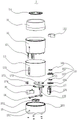
Fig. 1 is a schematic diagram of an explosion state structure of an aromatherapy humidifier with a built-in rotating disk.
Fig. 2 and 3 are schematic structural diagrams of cross-sectional states of the aromatherapy humidifier with a built-in rotating disk.
[ detailed description of the invention ]
For the purpose of making the objects, technical solutions and advantages of the present invention more apparent, the present invention will be further described in detail below with reference to the accompanying drawings and embodiments. It should be understood that the specific embodiments described herein are merely illustrative of the invention and are not intended to limit the invention.
Referring to fig. 1 to 3, an aroma humidifier 1 with a built-in rotating disc according to the present invention includes a main body, a control circuit board 19 disposed inside the main body, a turbo fan 171, and an atomizing plate assembly 18;
an air duct 123 for conveying air fanned by the turbo fan 171 to the inside of the main body is provided inside the main body;
a rotary disk mechanism disposed between one end of the air duct 123 and the turbo fan 171; the rotary disc mechanism comprises a driving motor 16, a supporting frame 17 for installing the driving motor 16 and a rotary disc 172 which is arranged on the supporting frame 17 and driven by the driving motor 16 to rotate; the rotary disc 172 is provided with a vent hole 1721 matched with the shape of the air duct 123 or the connection part of the air duct 123 and the turbofan 171;
the upper part of the main machine body is provided with a spray ring opening 111 for spraying mist;
the turbofan 171, the atomizing plate assembly 18, and the driving motor 16 are electrically connected to the control circuit board 19.
The present application is provided with a main body, a control circuit board 19 arranged inside the main body, a turbofan 171 and an atomizing plate assembly 18; an air duct 123 for conveying the air fanned by the turbofan 171 to the inner side of the main body is arranged in the main body, and a rotating disk mechanism is arranged between one end of the air duct 123 and the turbofan 171; the rotary disc mechanism comprises a driving motor 16, a supporting frame 17 for installing the driving motor 16 and a rotary disc 172 which is arranged on the supporting frame 17 and driven by the driving motor 16 to rotate; the rotary disc 172 is provided with a vent hole 1721 which is matched with the shape of the connection part of the air duct 123 or the air duct 123 and the turbofan 171, the upper part of the main body is provided with a ring spraying opening 111 for spraying mist, in the actual operation process, the rotary disc 172 can be driven by the driving motor 16 to rotate, and the air blown by the turbofan 171 can be blocked at intervals by combining the structural design of the vent hole 1721, when the rotary disc 172 rotates to the position where the vent hole 1721 is overlapped with the air duct 123 or the connection part of the air duct 123 and the turbofan 171, the air is conveyed into the main body through the vent hole 123, the mist in the main body is pressed to be extruded to the ring spraying opening 111 to form a vortex ring, and the rotary disc 172 is opposite to a gate structure.
The application does not relate to the improvement of software or circuit parts, and each functional component is a conventional technical component in the field, and the application mainly protects the integral structural construction of the humidifier.
The structural design that the driving motor 16 drives the rotating disc 172 to rotate can also be a similar waterwheel rotating structure, and the structures that can form a barrier to the air duct 123 are equivalent alternative structures and schemes.
Preferably, an atomizing cavity 12 for storing water is arranged inside the main machine body; and the atomization plate assembly 18 is arranged at the bottom of the atomization cavity 12; the air duct 123 is communicated with the atomizing chamber 12.
The air duct 123 introduces air from the turbo fan 171 into the atomizing chamber 12, so that the mist in the atomizing chamber 12 is unbalanced and is ejected from the ring nozzle 111.
Preferably, the main body further comprises an upper cover 11, a middle shell 13 and a bottom shell 15; the atomizing cavity 12 is positioned at the inner side part of the middle shell 13; the upper cover 11 is connected with the middle shell 13 and the upper part of the atomizing cavity 12 in a matching way; the upper part of the bottom shell 15 is connected with the middle shell 13 or the atomizing cavity 12 in a matching way.
The bottom of the atomizing chamber 12 is integrally formed with a connecting rod 121 for connecting with the bottom shell 15.
Preferably, a detection switch 173 for sensing a rotation state of the rotary disk 172 is further provided inside the main body; the detection switch 173 is electrically connected to the control circuit board 19.
The present application does not limit the specific type of the detection switch 173, but mainly includes any detection elements that can sense the rotation angle or state of the rotating disk 172 and the position of the vent 1721, such as magnetic induction sensors.
The bottom of the bottom shell 15 is also provided with a foot pad.
Preferably, the atomization sheet assembly 18 comprises an atomization sheet seat 182, an atomization sheet 183 and an atomization sheet pressing plate 184; the atomizing sheet seat 182 is also sleeved with a sealing ring 181; the atomizing sheet pressing plate 184 is connected to the bottom of the atomizing chamber 12, and the atomizing sheet seat 182, the sealing ring 181 and the atomizing sheet 183 are fixed to the bottom of the atomizing chamber 12.
Preferably, the detection switch 173 is a photoelectric switch sensor; a notch for allowing light to pass through the rotating disc 172 is formed in the outer edge of the rotating disc 172; the detection switch 173 is fixedly disposed on the supporting frame 17.
Preferably, the air duct 123 is integrally formed with the atomizing chamber; and an air flap 122 for controlling the air flowing-out direction is arranged at the outlet part of the air duct 123 extending into the atomizing chamber 12.
Preferably, the support bracket 17 includes a horizontal mounting plate for installing the rotary disk 172 and the driving motor 16 and a vertical mounting plate 175 for fixing the turbo fan 171; the rotary disk 172 axially rotates about a rotary shaft mounted on the horizontal mounting plate; a plate hole matched with the air outlet of the turbofan 171 is formed on the horizontal mounting plate. Meanwhile, in order to stably mount the sensing switch 173, a sensing switch mounting groove 174 for fixing the sensing switch 173 is further formed at an outer side of the horizontal mounting plate.
Preferably, the nozzle 111 is opened on the upper cover 11; a flow limiting cover 14 for adjusting the size of the nozzle 111 is further arranged on the upper cover 11; the flow-limiting cover 14 is provided with a flow-limiting hole matched with the size of the ring-spraying opening 111.
Preferably, an exhaust fan 152 is further fixedly arranged at the bottom of the bottom shell 15; the bottom shell 15 is provided with a vent hole; the exhaust fan 152 is arranged close to the vent hole; the switch device further comprises a switch button 151 arranged on the outer side of the bottom shell 15 and a power supply inlet 191.
A plurality of ventilation columns 153 at equal intervals are integrally formed and densely distributed on the periphery of the upper end of the bottom shell 15; the lower part of the middle shell 13 is matched, clamped and connected with a plurality of ventilation columns 153 of the bottom shell 15; the outside air introduced by the suction fan 152 is discharged from the gaps between the ventilation duct 123 and the plurality of ventilation columns 153.
The inner side of the upper cover 11 is also integrally formed with a water guard 112 for catching water splash pushed up by the atomizing plate assembly 18.
Compared with the prior art, the aroma humidifier 1 with the built-in rotating disc is provided with the host body, the control circuit board 19 arranged in the host body, the turbofan 171 and the atomizing sheet assembly 18 at the same time; an air duct 123 for conveying the air fanned by the turbofan 171 to the inner side of the main body is arranged in the main body, and a rotating disk mechanism is arranged between one end of the air duct 123 and the turbofan 171; the rotary disc mechanism comprises a driving motor 16, a supporting frame 17 for installing the driving motor 16 and a rotary disc 172 which is arranged on the supporting frame 17 and driven by the driving motor 16 to rotate; the rotary disc 172 is provided with a vent hole 1721 which is matched with the shape of the connection part of the air duct 123 or the air duct 123 and the turbofan 171, the upper part of the main body is provided with a ring spraying opening 111 for spraying mist, in the actual operation process, the rotary disc 172 can be driven by the driving motor 16 to rotate, and the air blown by the turbofan 171 can be blocked at intervals by combining the structural design of the vent hole 1721, when the rotary disc 172 rotates to the position where the vent hole 1721 is overlapped with the air duct 123 or the connection part of the air duct 123 and the turbofan 171, the air is conveyed into the main body through the vent hole 123, the mist in the main body is pressed to be extruded to the ring spraying opening 111 to form a vortex ring, and the rotary disc 172 is opposite to a gate structure.
The above-described embodiments of the present invention do not limit the scope of the present invention. Any modification, equivalent replacement, and improvement made within the spirit and principle of the present invention should be included in the scope of the claims of the present invention.
Claims (10)
1. The utility model provides a fragrance humidifier of built-in rotary disk which characterized in that: the atomizing device comprises a main machine body, a control circuit board arranged in the main machine body, a turbofan and an atomizing sheet assembly;
the main machine body is internally provided with an air duct for conveying air fanned by the turbofan to the inner side of the main machine body;
the rotary disc mechanism is arranged between one end of the air duct and the turbofan; the rotary disc mechanism comprises a driving motor, a supporting frame used for installing the driving motor and a rotary disc which is arranged on the supporting frame and driven by the driving motor to rotate; the rotating disc is provided with a vent hole matched with the shape of the ventilation channel or the connection part of the ventilation channel and the turbofan;
the upper part of the main machine body is provided with a spray ring opening for spraying mist;
the turbofan, the atomizing sheet assembly, the driving motor and the control circuit board are electrically connected.
2. The aroma humidifier with a built-in rotary disk as claimed in claim 1, wherein: an atomization cavity for storing water is arranged in the main machine body; the atomization plate assembly is arranged at the bottom of the atomization cavity; the air duct is communicated with the atomization cavity.
3. The aroma humidifier with a built-in rotary disk as claimed in claim 2, wherein: the main machine body further comprises an upper cover, a middle shell and a bottom shell; the atomization cavity is positioned at the inner side part of the middle shell; the upper cover is connected with the middle shell and the upper part of the atomizing cavity in a matching way; the upper part of the bottom shell is connected with the middle shell or the atomizing cavity in a matching way.
4. The aroma humidifier with a built-in rotary disk as claimed in any one of claims 1 to 3, wherein: a detection switch for sensing the rotating state of the rotating disc is further arranged in the main machine body; the detection switch is electrically connected with the control circuit board.
5. The aroma humidifier with a built-in rotary disk as claimed in claim 3, wherein: the atomization plate assembly comprises an atomization plate seat, an atomization plate and an atomization plate pressing plate; the atomizing sheet seat is also sleeved with a sealing ring; the atomizing sheet pressing plate is connected with the bottom of the atomizing cavity, and the atomizing sheet seat, the sealing ring and the atomizing sheet are fixed at the bottom of the atomizing cavity.
6. The aroma humidifier with a built-in rotary disk as claimed in claim 4, wherein: the detection switch is a photoelectric switch sensor; a notch for enabling light to pass through the rotating disc is formed in the outer edge of the rotating disc; the detection switch is fixedly arranged on the support frame.
7. The aroma humidifier with a built-in rotary disk as claimed in claim 2, wherein: the air duct and the atomization cavity are integrally formed; and an air port cover used for controlling the air outflow direction is arranged at the outlet part of the air duct extending into the atomizing cavity.
8. The aroma humidifier with a built-in rotary disk as claimed in claim 2 or 3, wherein: the support frame comprises a horizontal mounting plate for installing the rotating disc and the driving motor and a vertical mounting plate for fixing the turbofan; the rotating disc axially rotates around a rotating shaft arranged on the horizontal mounting plate; and the horizontal mounting plate is provided with a plate hole matched with the air outlet of the turbofan.
9. The aroma humidifier with a built-in rotary disk as claimed in claim 3, wherein: the spray ring opening is formed in the upper cover; the upper cover is also provided with a flow limiting cover for adjusting the size of the spray ring opening; and the flow limiting cover is provided with a flow limiting hole matched with the size of the spray ring opening.
10. The aroma humidifier with a built-in rotary disk as claimed in claim 3, wherein: an exhaust fan is fixedly arranged at the bottom of the bottom shell; the bottom shell is provided with a vent hole; the exhaust fan is arranged close to the vent hole; the switch button and the power supply access port are arranged on the outer side of the bottom shell.
Priority Applications (2)
| Application Number | Priority Date | Filing Date | Title |
|---|---|---|---|
| CN202011318192.2A CN112303777A (en) | 2020-11-23 | 2020-11-23 | Aroma humidifier with built-in rotating disc |
| PCT/CN2021/120334 WO2022105422A1 (en) | 2020-11-23 | 2021-09-24 | Aroma air humidifier provided with rotating plate therein |
Applications Claiming Priority (1)
| Application Number | Priority Date | Filing Date | Title |
|---|---|---|---|
| CN202011318192.2A CN112303777A (en) | 2020-11-23 | 2020-11-23 | Aroma humidifier with built-in rotating disc |
Publications (1)
| Publication Number | Publication Date |
|---|---|
| CN112303777A true CN112303777A (en) | 2021-02-02 |
Family
ID=74335164
Family Applications (1)
| Application Number | Title | Priority Date | Filing Date |
|---|---|---|---|
| CN202011318192.2A Pending CN112303777A (en) | 2020-11-23 | 2020-11-23 | Aroma humidifier with built-in rotating disc |
Country Status (2)
| Country | Link |
|---|---|
| CN (1) | CN112303777A (en) |
| WO (1) | WO2022105422A1 (en) |
Cited By (2)
| Publication number | Priority date | Publication date | Assignee | Title |
|---|---|---|---|---|
| WO2022105422A1 (en) * | 2020-11-23 | 2022-05-27 | 李春盛 | Aroma air humidifier provided with rotating plate therein |
| WO2022193948A1 (en) * | 2021-03-14 | 2022-09-22 | 李春盛 | Decorative aromatherapy humidifier |
Families Citing this family (1)
| Publication number | Priority date | Publication date | Assignee | Title |
|---|---|---|---|---|
| CN112460717A (en) * | 2020-12-08 | 2021-03-09 | 李春盛 | Solenoid valve control type aromatherapy humidifier |
Citations (3)
| Publication number | Priority date | Publication date | Assignee | Title |
|---|---|---|---|---|
| CN1101117A (en) * | 1993-06-24 | 1995-04-05 | 三星电子株式会社 | An automatic outlet opening/closing apparatus of an air-conditioner |
| JP2015200454A (en) * | 2014-04-08 | 2015-11-12 | 有限会社エフ・アンド・エフ | Vapor generator |
| JP2019211132A (en) * | 2018-06-01 | 2019-12-12 | ダイキン工業株式会社 | Blower device |
Family Cites Families (7)
| Publication number | Priority date | Publication date | Assignee | Title |
|---|---|---|---|---|
| KR20110022848A (en) * | 2009-08-28 | 2011-03-08 | 삼성전자주식회사 | Air cleaning humidifier |
| CN208312613U (en) * | 2018-06-07 | 2019-01-01 | 杨向征 | A kind of humidifier |
| CN210583204U (en) * | 2018-12-21 | 2020-05-22 | 佛山市南海科日超声电子有限公司 | Novel aromatherapy machine |
| CN109529088A (en) * | 2018-12-21 | 2019-03-29 | 佛山市南海科日超声电子有限公司 | One kind gushing mist fumigating machine |
| CN209782901U (en) * | 2019-05-20 | 2019-12-13 | 李�荣 | Spraying structure capable of spraying mist ring humidifier |
| CN112303777A (en) * | 2020-11-23 | 2021-02-02 | 李春盛 | Aroma humidifier with built-in rotating disc |
| CN213687110U (en) * | 2020-11-23 | 2021-07-13 | 李春盛 | Aroma humidifier with built-in rotating disc |
-
2020
- 2020-11-23 CN CN202011318192.2A patent/CN112303777A/en active Pending
-
2021
- 2021-09-24 WO PCT/CN2021/120334 patent/WO2022105422A1/en active Application Filing
Patent Citations (3)
| Publication number | Priority date | Publication date | Assignee | Title |
|---|---|---|---|---|
| CN1101117A (en) * | 1993-06-24 | 1995-04-05 | 三星电子株式会社 | An automatic outlet opening/closing apparatus of an air-conditioner |
| JP2015200454A (en) * | 2014-04-08 | 2015-11-12 | 有限会社エフ・アンド・エフ | Vapor generator |
| JP2019211132A (en) * | 2018-06-01 | 2019-12-12 | ダイキン工業株式会社 | Blower device |
Cited By (2)
| Publication number | Priority date | Publication date | Assignee | Title |
|---|---|---|---|---|
| WO2022105422A1 (en) * | 2020-11-23 | 2022-05-27 | 李春盛 | Aroma air humidifier provided with rotating plate therein |
| WO2022193948A1 (en) * | 2021-03-14 | 2022-09-22 | 李春盛 | Decorative aromatherapy humidifier |
Also Published As
| Publication number | Publication date |
|---|---|
| WO2022105422A1 (en) | 2022-05-27 |
Similar Documents
| Publication | Publication Date | Title |
|---|---|---|
| CN112303777A (en) | Aroma humidifier with built-in rotating disc | |
| CN213687110U (en) | Aroma humidifier with built-in rotating disc | |
| CN202746301U (en) | Fan assembly | |
| CN107940593A (en) | A kind of air purifier | |
| WO2022193948A1 (en) | Decorative aromatherapy humidifier | |
| WO2022242229A1 (en) | Water-washing air apparatus and cabinet air conditioner | |
| CN205505285U (en) | Centrifugation atomizing axial fan | |
| CN208765150U (en) | Single centrifuge disc type humidifier | |
| US11549701B2 (en) | Humidification and air cleaning apparatus | |
| CN213983876U (en) | Solenoid valve control type aromatherapy humidifier | |
| CN215723826U (en) | Aromatherapy humidifier with decorative effect | |
| CN114110856A (en) | Built-in rotary cylinder type aromatherapy humidifier | |
| CN215723827U (en) | Ornament champignon humidifier | |
| CN208765151U (en) | Double centrifuge disc type humidifiers | |
| CN207507196U (en) | A kind of air purifier | |
| CN216644436U (en) | Rotary atomizing type intelligent aromatherapy humidifier | |
| CN205747421U (en) | A kind of noise reduction system of aeration device | |
| CN216977043U (en) | Built-in rotary cylinder type aromatherapy humidifier | |
| CN114165872A (en) | Surrounding spray type aromatherapy humidifier | |
| CN214701071U (en) | High-flexibility spray ring aromatherapy humidifier | |
| CN217031470U (en) | Aromatherapy humidifier capable of flexibly switching modes | |
| CN113959028A (en) | Air pump type spray ring aromatherapy humidifier | |
| CN216953347U (en) | Aroma humidifier | |
| CN108954629B (en) | Single centrifugal disc type humidifier | |
| CN205448109U (en) | Cooling fan |
Legal Events
| Date | Code | Title | Description |
|---|---|---|---|
| PB01 | Publication | ||
| PB01 | Publication | ||
| SE01 | Entry into force of request for substantive examination | ||
| SE01 | Entry into force of request for substantive examination |