CN112298552B - A miniature dual flapping-wing aircraft capable of autonomous stability enhancement and control and its control torque generation method - Google Patents
A miniature dual flapping-wing aircraft capable of autonomous stability enhancement and control and its control torque generation method Download PDFInfo
- Publication number
- CN112298552B CN112298552B CN202010782988.7A CN202010782988A CN112298552B CN 112298552 B CN112298552 B CN 112298552B CN 202010782988 A CN202010782988 A CN 202010782988A CN 112298552 B CN112298552 B CN 112298552B
- Authority
- CN
- China
- Prior art keywords
- wing
- flapping
- control
- aircraft
- rod
- Prior art date
- Legal status (The legal status is an assumption and is not a legal conclusion. Google has not performed a legal analysis and makes no representation as to the accuracy of the status listed.)
- Active
Links
Images


Classifications
-
- B—PERFORMING OPERATIONS; TRANSPORTING
- B64—AIRCRAFT; AVIATION; COSMONAUTICS
- B64C—AEROPLANES; HELICOPTERS
- B64C33/00—Ornithopters
- B64C33/02—Wings; Actuating mechanisms therefor
-
- G—PHYSICS
- G05—CONTROLLING; REGULATING
- G05D—SYSTEMS FOR CONTROLLING OR REGULATING NON-ELECTRIC VARIABLES
- G05D1/00—Control of position, course, altitude or attitude of land, water, air or space vehicles, e.g. using automatic pilots
- G05D1/08—Control of attitude, i.e. control of roll, pitch, or yaw
- G05D1/0808—Control of attitude, i.e. control of roll, pitch, or yaw specially adapted for aircraft
- G05D1/0816—Control of attitude, i.e. control of roll, pitch, or yaw specially adapted for aircraft to ensure stability
-
- Y—GENERAL TAGGING OF NEW TECHNOLOGICAL DEVELOPMENTS; GENERAL TAGGING OF CROSS-SECTIONAL TECHNOLOGIES SPANNING OVER SEVERAL SECTIONS OF THE IPC; TECHNICAL SUBJECTS COVERED BY FORMER USPC CROSS-REFERENCE ART COLLECTIONS [XRACs] AND DIGESTS
- Y02—TECHNOLOGIES OR APPLICATIONS FOR MITIGATION OR ADAPTATION AGAINST CLIMATE CHANGE
- Y02T—CLIMATE CHANGE MITIGATION TECHNOLOGIES RELATED TO TRANSPORTATION
- Y02T50/00—Aeronautics or air transport
- Y02T50/40—Weight reduction
Landscapes
- Engineering & Computer Science (AREA)
- Aviation & Aerospace Engineering (AREA)
- Radar, Positioning & Navigation (AREA)
- Remote Sensing (AREA)
- Physics & Mathematics (AREA)
- General Physics & Mathematics (AREA)
- Automation & Control Theory (AREA)
- Toys (AREA)
Abstract
本发明公开了一种可自主增稳控制的微型双扑翼飞行器及其三自由度控制力矩产生方法,具体包括完全相同的两套驱动系统、升力系统和控制系统,两组驱动系统通过中间连接结构连接,驱动系统带动升力系统产生升力,控制系统改变升力系统产生控制力矩。该飞行器能够高效地产生俯仰、滚转、偏航三轴控制力矩,并通过互补滤波与卡尔曼滤波算法估计飞行器状态信息并做出自主增稳控制。本发明飞行器具有自主增稳飞行能力,着重改善了偏航性能,仅通过改变翼膜张紧程度控制滚转与偏航,避免了对控制不利的重心变化,且减少了增稳控制过程中的升力损失。
The invention discloses a miniature double flapping-wing aircraft capable of autonomous stability enhancement and control and a three-degree-of-freedom control torque generation method, which specifically includes two identical sets of drive systems, lift systems and control systems, and the two sets of drive systems are connected through the middle Structural connection, the drive system drives the lift system to generate lift, and the control system changes the lift system to generate control torque. The aircraft can efficiently generate three-axis control torques of pitch, roll and yaw, and estimates the state information of the aircraft through complementary filtering and Kalman filtering algorithms, and makes autonomous stabilization control. The aircraft of the present invention has the capability of autonomously increasing the stability of the flight, and emphatically improves the yaw performance. The roll and yaw are controlled only by changing the tension degree of the wing membrane, which avoids the change of the center of gravity which is unfavorable for the control, and reduces the time of the stabilization control process. lift loss.
Description
技术领域technical field
本发明涉及微型飞行器领域,具体来说是一种可自主增稳控制的微型双扑翼飞行器及其控制力矩产生方法。The invention relates to the field of micro aircraft, in particular to a miniature dual flapping-wing aircraft capable of autonomous stability enhancement and control and a control torque generating method thereof.
背景技术Background technique
随着上世纪末飞行器设计理念的不断创新和微电子技术的大幅进步,微型飞行器被提出并快速发展。微型飞行器具有体积小、重量轻和机动性强等特征,适用于复杂环境下的侦查、勘探和协助救援等工作,应用前景广泛。仿生微型扑翼飞行器作为微型飞行器的一个重要分支,随着仿生学设计的发展逐渐开始出现。扑翼微型飞行器依靠扑翼的往复拍动产生升力,通过对扑翼拍动过程的细微控制产生控制力矩,其可在低雷诺数下保持较高的气动效率及灵敏的机动性,具备垂直起降、悬停等飞行能力。With the continuous innovation of aircraft design concepts and the great progress of microelectronics technology at the end of the last century, MAVs were proposed and developed rapidly. Micro air vehicles have the characteristics of small size, light weight and strong maneuverability. They are suitable for reconnaissance, exploration and rescue assistance in complex environments, and have broad application prospects. As an important branch of micro air vehicle, bionic micro flapping-wing vehicle gradually began to appear with the development of bionic design. The flapping-wing MAV relies on the reciprocating flapping of the flapping wing to generate lift, and generates control torque through the fine control of the flapping process of the flapping wing. landing, hovering and other flight capabilities.
仿昆虫扑翼飞行器模仿自然界中的蜂、蝇等飞行生物,大多具有一对翅膀,其升力、控制力矩均依靠仅有的一对翼产生,因此这导致这类飞行器普遍存在升力不足、控制舵效较低、控制方案复杂等问题。为解决上述问题,现今提出了微型双扑翼飞行器,此类飞行器有前后两对扑翼,翼数量的增加增大了升力,对前后两对翼的整体控制进行力矩控制和姿态控制,降低了控制舵效和控制设计的难度。上述特征为研制大载荷微型飞行器提供了有效方案。Insect-like flapping-wing aircraft imitates flying creatures such as bees and flies in nature. Most of them have a pair of wings, and their lift and control torque are generated by the only pair of wings. Therefore, this type of aircraft generally suffers from insufficient lift and rudder control. problems such as low efficiency and complex control schemes. In order to solve the above problems, a miniature double flapping-wing aircraft is now proposed. This type of aircraft has two pairs of flapping wings at the front and rear. The increase in the number of wings increases the lift, and performs torque control and attitude control on the overall control of the two pairs of wings. Difficulty in controlling rudder effect and control design. The above features provide an effective solution for the development of large-load MAVs.
微型双扑翼飞行器没有尾翼,其飞行是动不稳定的;此外,微型双扑翼飞行器在扑翼反复扑动时会产生振动,这加剧了飞行的动不稳定性,这也为飞行器运动信息的精确解算带来了困难,因此微型双扑翼飞行器实际稳定飞行需要增稳控制和精确的姿态解算能力。The miniature dual flapping-wing aircraft has no tail, and its flight is dynamically unstable; in addition, the miniature dual-flap-wing aircraft will vibrate when the flapping wings repeatedly flap, which aggravates the dynamic instability of flight, which also provides information for the movement of the aircraft. The precise solution of , brings difficulties, so the actual stable flight of the miniature dual flapping-wing aircraft requires enhanced stability control and accurate attitude calculation capabilities.
实际制造的飞行器传动机构、扑翼在制造和装配时无法保证严格对称,因此其左右扑翼产生的力有差别,因此飞行器无法避免初始偏航力矩的存在,无偏航控制飞行器飞行时会不停绕竖直轴旋转。因此,应着重开发或改进微型双扑翼飞行器的偏航控制。The actual aircraft transmission mechanism and flapping wings cannot be strictly symmetrical during manufacture and assembly, so the forces generated by the left and right flapping wings are different, so the aircraft cannot avoid the existence of the initial yaw moment, and the aircraft without yaw control will not fly when flying. Stop rotating around the vertical axis. Therefore, the development or improvement of the yaw control of the micro twin flapping-wing vehicle should be emphasized.
过往微型扑翼飞行器还存在控制机构响应较慢、舵效不足,控制力矩产生会带来较大的升力损失的问题,如专利“一种微型四扑翼飞行器”(CN 110712751A)公开了一种扑翼飞行器,其利用直线舵机拉动翼根杆的方式进行滚转和偏航控制,直线舵机相较旋转舵机反应速度慢、定位能力差,难以快速地定位翼根杆,因此扑翼难以及时提供足够的气动力,滚转、偏航方向控制舵效也不足。此外,该设计通过每对扑翼系统的整体转动改变气动力产生控制力矩,控制力矩产生的同时合力在竖直方向的分量减小,这导致有效升力不足。In the past, the miniature flapping-wing aircraft also had the problems that the control mechanism was slow to respond, the rudder effect was insufficient, and the generation of the control torque would bring about a large loss of lift. The flapping aircraft uses the linear steering gear to pull the wing root rod for roll and yaw control. Compared with the rotary steering gear, the linear steering gear has a slower response speed and poorer positioning ability, and it is difficult to quickly locate the wing root rod. It is difficult to provide sufficient aerodynamic force in time, and the rudder effect of roll and yaw direction control is also insufficient. In addition, this design changes the aerodynamic force through the overall rotation of each pair of flapping wing systems to generate a control torque, and the control torque is generated while the component of the resultant force in the vertical direction is reduced, which leads to insufficient effective lift.
除上述问题之外,过去微型扑翼飞行器进行姿态控制过程还会伴随飞行器重心的变化。如专利“一种微型四扑翼飞行器”(CN 110712751A)、“一种适用于微型四扑翼飞行器的传动机构”(CN 110525647 A)公布的具有三自由度控制能力的微型双扑翼飞行器大多采用将飞行器机构、扑翼、电机作为整体进行移动的控制力矩产生方式,该种方式会导致飞行器重心的变化,也不利于飞行器的稳定控制。In addition to the above problems, in the past, the attitude control process of the micro flapping-wing aircraft was accompanied by the change of the center of gravity of the aircraft. For example, the patents "A Micro Four-Flopping Aircraft" (CN 110712751A), "A Transmission Mechanism Applicable to a Micro Four-Flopping Aircraft" (CN 110525647 A) are mostly micro-double flapping aircraft with three degrees of freedom control capability. The control torque generation method in which the aircraft mechanism, flapping wing and motor are moved as a whole is adopted, which will cause the change of the center of gravity of the aircraft and is not conducive to the stable control of the aircraft.
总的来看,目前仍有必要发明一种微型双扑翼飞行器,使其具有偏航姿态控制能力,同时在保证控制过程升力少损失、飞行器重心小变化的基础上增强俯仰、滚转及偏航力矩产生舵效。In general, it is still necessary to invent a miniature dual flapping-wing aircraft, which has the ability to control the yaw attitude, and at the same time enhance the pitch, roll and yaw on the basis of ensuring less loss of lift during the control process and small changes in the center of gravity of the aircraft. Navigation moment produces rudder effect.
发明内容SUMMARY OF THE INVENTION
本发明针对现有微型双扑翼飞行器的增稳控制与偏航控制问题,同时为解决飞行器控制舵效低、控制力矩产生过程中飞行器易损失升力、重心位置易改变等问题,发明了一种可自主增稳控制的微型双扑翼飞行器及其控制力矩产生方法。该飞行器采用前后两对扑翼产生升力,具有俯仰、滚转、偏航三轴姿态自主增稳控制能力。该微型双扑翼飞行器借助旋转舵机改变柔性扑翼膜的张紧程度改变翼上的气动力和力矩,而不再通过改变前后两套拍动机构的相对位置来产生控制力矩,实现了舵效增强、升力损失降低以及重心位置不变,增强了控制效果并降低了控制难度。The present invention aims at the problems of stabilization control and yaw control of the existing miniature double flapping-wing aircraft, and at the same time, in order to solve the problems of low control rudder efficiency of the aircraft, easy loss of lift of the aircraft during the generation of control torque, and easy change of the position of the center of gravity, a new method is invented. A miniature dual flapping-wing aircraft capable of autonomous stability augmentation and control and a control torque generation method thereof. The aircraft uses two pairs of flapping wings in the front and rear to generate lift, and has the ability to independently increase the attitude of pitch, roll and yaw. The miniature double flapping-wing aircraft changes the aerodynamic force and torque on the wing by changing the tension of the flexible flapping membrane by rotating the steering gear, instead of generating the control torque by changing the relative positions of the front and rear flapping mechanisms, realizing the rudder Enhanced efficiency, reduced lift loss, and unchanged center of gravity position enhance the control effect and reduce the difficulty of control.
一种可自主增稳控制的微型双扑翼飞行器,包含中间连接结构、前后两套完全相同的扑翼系统以及增稳控制系统,所述中间连接结构将前后两套完全相同的扑翼系统连接为一个整体,所述扑翼系统实现气动力和控制力矩产生,所述增稳控制系统用于飞行过程中的增稳控制,以消除飞行器飞行的动不稳定性。A miniature dual flapping-wing aircraft capable of autonomous stability enhancement and control, comprising an intermediate connection structure, two sets of identical flapping wing systems at the front and rear, and a stability augmentation control system, the intermediate connection structure connecting the front and rear two sets of identical flapping wing systems As a whole, the flapping system realizes the generation of aerodynamic force and control torque, and the stabilization control system is used for stabilization control during flight, so as to eliminate the dynamic instability of the flight of the aircraft.
所述中间连接结构为立体结构,所述立体结构上部前后两端开有两个底座安装孔,用于固定所述前后两套扑翼系统的底座,以将两套扑翼系统组合为一个整体。The intermediate connection structure is a three-dimensional structure, and two base mounting holes are opened at the front and rear ends of the upper part of the three-dimensional structure for fixing the bases of the two sets of flapping wing systems at the front and rear, so as to combine the two sets of flapping wing systems into a whole. .
所述扑翼系统共有两套,每套均包括拍动机构及扑翼。There are two sets of the flapping wing system, and each set includes a flapping mechanism and flapping wings.
所述拍动机构包括空心杯电机、减速齿轮组、拍动角放大机构及底座。所述空心杯电机为大功率有刷电机。所述减速齿轮组为二级直齿减速轮组。所述拍动角放大机构为曲柄-连杆机构。所述底座经3D打印整体成型,为左右对称结构。The flapping mechanism includes a hollow cup motor, a reduction gear set, a flapping angle amplifying mechanism and a base. The hollow cup motor is a high-power brushed motor. The reduction gear set is a secondary straight-tooth reduction gear set. The flapping angle amplifying mechanism is a crank-link mechanism. The base is integrally formed by 3D printing and has a left-right symmetrical structure.
所述扑翼由翼膜、主翼杆、辅翼杆、翼根杆组成。翼膜为柔性薄膜,通常采用聚乙烯材料等做成,呈仿生扑翼状。所述翼膜前缘与所述主翼杆连接,所述辅翼杆与所述主翼杆呈30°粘连在所述翼膜上,所述翼膜平铺状态下所述翼根杆与所述翼膜左侧粘连且与翼膜前缘呈110°-120°,所述扑翼安装之后,所述翼根杆与所述主翼杆垂直,以便使所述翼膜在安装后松弛;拍动过程中,所述主翼杆带动所述辅翼杆和翼膜高频往复拍动,所述辅翼杆和翼膜在惯性力和气动力的作用下发生变形,所述翼膜的最大变形受所述翼根杆位置的约束,使得上下拍中间时刻翼展向面积二阶矩位置处的攻角(定义为翼拍动平面与翼面积二阶矩位置处展向截面的攻角)在25°-35°之间,以维持较高的气动效率。所述扑翼系统在上下拍中间时刻通过改变翼根杆的前后左右位置,可改变翼膜的张紧程度,进而改变上下拍攻角产生不同的气动力和气动力矩。The flapping wing is composed of a wing membrane, a main wing bar, an auxiliary wing bar and a wing root bar. The wing film is a flexible film, usually made of polyethylene materials, etc., in the shape of a bionic flapping wing. The leading edge of the wing film is connected to the main wing rod, the auxiliary wing rod and the main wing rod are adhered to the wing film at a 30° angle, and the wing root rod and the The left side of the wing membrane is adhered and is at 110°-120° with the leading edge of the wing membrane. After the flapping wing is installed, the wing root bar is perpendicular to the main wing bar, so that the wing membrane is relaxed after installation; flapping; During the process, the main wing rod drives the auxiliary wing rod and the wing membrane to flap back and forth at high frequency, the auxiliary wing rod and the wing membrane are deformed under the action of inertial force and aerodynamic force, and the maximum deformation of the wing membrane is affected by The above-mentioned constraints on the position of the wing root rod make the angle of attack at the position of the second moment of the spanwise area at the middle of the up and down beat (defined as the angle of attack of the spanwise section at the position of the wing flap plane and the second moment of the wing area) at 25°. -35° to maintain high aerodynamic efficiency. The flapping wing system can change the tension degree of the wing membrane by changing the front, rear, left and right positions of the wing root rod at the middle moment of the up and down beats, thereby changing the angle of attack of the up and down beats to generate different aerodynamic forces and aerodynamic moments.
所述增稳控制系统包含姿态控制舵机、翼根位置控制机构及飞行控制电路板。The stability augmentation control system includes an attitude control steering gear, a wing root position control mechanism and a flight control circuit board.
所述姿态控制舵机为微小型大扭矩旋转舵机,一前一后分布在底座的正下方,通过所述姿态控制舵机的摇臂驱动所述翼根位置控制机构左右移动,改变所述翼根杆位置调整所述翼膜上下拍时的张紧程度,在上下拍过程中产生非对称的气动力,从而获得气动控制力矩。The attitude control steering gear is a micro-miniature high-torque rotary steering gear, which is distributed in front and back directly under the base. The rocker arm of the attitude control steering gear drives the wing root position control mechanism to move left and right, changing the The position of the wing root rod adjusts the degree of tension of the wing membrane when shooting up and down, so as to generate asymmetric aerodynamic force in the process of shooting up and down, so as to obtain aerodynamic control torque.
所述翼根位置控制机构共有两个,分别控制所述前后一对扑翼的翼根杆位置;所述翼根位置控制机构呈T形,在左右两个端点设孔约束所述翼根杆位置,在中间梁设槽与所述姿态控制舵机的摇臂连接,所述翼根控制机构将所述姿态控制舵机的转动转换为所述翼根位置控制机构的左右移动,带动所述翼根杆左右摆动。There are two wing root position control mechanisms, which respectively control the position of the wing root rods of the front and rear pair of flapping wings; the wing root position control mechanism is T-shaped, and holes are set at the left and right end points to constrain the wing root rods. position, a groove is set in the middle beam to connect with the rocker arm of the attitude control steering gear, the wing root control mechanism converts the rotation of the attitude control steering gear into the left and right movement of the wing root position control mechanism, and drives the The wing root bar swings left and right.
所述飞行控制电路板为采用MEMS工艺制造、微型、轻型的机载电路板,包含主控芯片和机载传感器,其中主控芯片用于运行增稳控制算法;所述机载传感器集成了加速度计、陀螺仪及磁力计,分别测量飞行器的加速度、角速度、磁方位角数据;所述机载传感器测量的数据经低通滤波处理后,在所述主控芯片中通过互补滤波和扩展卡尔曼滤波组成的姿态估计算法计算出飞行器的三轴角速度与三轴姿态角。为准确获取飞行器飞行参数,该飞行控制电路板借助泡沫胶粘接在中间连接结构上并靠近飞行器重心。The flight control circuit board is a miniature, lightweight airborne circuit board manufactured by MEMS technology, including a main control chip and an airborne sensor, wherein the main control chip is used to run the stabilization control algorithm; the airborne sensor integrates the acceleration It measures the acceleration, angular velocity and magnetic azimuth data of the aircraft respectively; after the data measured by the airborne sensor is processed by low-pass filtering, complementary filtering and extended Kalman are passed in the main control chip. The attitude estimation algorithm composed of filtering calculates the triaxial angular velocity and triaxial attitude angle of the aircraft. In order to accurately obtain the flight parameters of the aircraft, the flight control circuit board is bonded to the intermediate connecting structure by means of foam glue and is close to the center of gravity of the aircraft.
由于扑翼扑动时产生的振动对传感器的数据采集造成了严重干扰,加速度计的采集数据尤为不准确。尽管互补滤波算法中利用陀螺仪对加速度计数据进行了一次修正,但仅仅依靠互补滤波解算的飞行姿态信息仍无法直接用于增稳控制。扩展卡尔曼滤波算法利用加速度计与磁力计直接解算出的姿态角作为观测量,在扑翼振动影响下,姿态解算结果也不够精确。单独使用任何一种方法均不能够满足高精度姿态解算要求。因此,本发明的姿态估计算法同时采用了互补滤波和扩展卡尔曼滤波的方式,利用互补滤波算法修正后的姿态角作为扩展卡尔曼滤波的观测变量,然后进行扩展卡尔曼滤波解算飞行器运动数据,能够有效抑制振动噪声,并减小姿态角随振动的漂移。The data collected by the accelerometer is particularly inaccurate because the vibration generated by the flapping wings seriously interferes with the data collection of the sensor. Although the accelerometer data is corrected once by using the gyroscope in the complementary filtering algorithm, the flight attitude information calculated only by the complementary filtering cannot be directly used for stabilization control. The extended Kalman filter algorithm uses the attitude angle directly calculated by the accelerometer and the magnetometer as the observation value. Under the influence of the flapping wing vibration, the attitude calculation result is not accurate enough. Neither method alone can meet the requirements of high-precision attitude calculation. Therefore, the attitude estimation algorithm of the present invention adopts the methods of complementary filtering and extended Kalman filtering at the same time, uses the attitude angle corrected by the complementary filtering algorithm as the observation variable of the extended Kalman filtering, and then performs the extended Kalman filtering to calculate the motion data of the aircraft. , which can effectively suppress vibration noise and reduce the drift of attitude angle with vibration.
一种可自主增稳控制的微型双扑翼飞行器的增稳飞行控制方法是内外两环的PID串级控制,外环控制器为姿态角控制器,内环控制器为角速度控制器;当飞行器受到扰动时,将无扰动理想状态下的三轴姿态角控制指令作为姿态角期望值,姿态角期望值与飞行控制电路板中的滤波算法解算出的三轴姿态角信息做差,差值作为姿态角控制器的输入值,经过外环PID控制,输出值直接作为三轴角速度期望值;之后,角速度期望值与飞行控制电路板中的滤波算法解算出的三轴角速度信息做差,差值作为角速度控制器的输入值,经过内环PID控制,输出为三轴增稳控制期望;最后,三轴增稳控制期望通过预先设置的混控矩阵,转换为两个电机与两个姿态控制舵机这四个通道的PWM波控制信号,通过脉冲宽度的占空比来控制电机转速与姿态控制舵机舵偏量,进而产生三轴控制力矩,使飞行器快速做出相应动作,消除期望姿态与实际姿态间的误差,达到增稳控制的目的。A stabilization flight control method for a miniature dual flapping-wing aircraft capable of autonomous stabilization control is PID cascade control of inner and outer loops, the outer loop controller is an attitude angle controller, and the inner loop controller is an angular velocity controller; When disturbed, the three-axis attitude angle control command in the undisturbed ideal state is used as the attitude angle expected value, the attitude angle expected value and the three-axis attitude angle information calculated by the filtering algorithm in the flight control circuit board are made difference, and the difference is used as the attitude angle. The input value of the controller is controlled by the outer loop PID, and the output value is directly used as the expected value of the three-axis angular velocity; after that, the expected value of the angular velocity and the three-axis angular velocity information calculated by the filtering algorithm in the flight control circuit board are made difference, and the difference is used as the angular velocity controller. After the inner loop PID control, the output is the three-axis stabilization control expectation; finally, the three-axis stabilization control expectation is converted into two motors and two attitude control servos through the preset mixing matrix. The PWM wave control signal of the channel controls the motor speed and the rudder offset of the attitude control servo through the duty cycle of the pulse width, thereby generating the three-axis control torque, so that the aircraft can quickly make corresponding actions, eliminating the difference between the desired attitude and the actual attitude. error, to achieve the purpose of stabilization control.
一种可自主增稳控制的微型双扑翼飞行器控制力矩产生方法包括滚转力矩、俯仰力矩以及偏航力矩产生方法。A method for generating control torque of a miniature dual flapping-wing aircraft capable of autonomous stability enhancement control includes a method for generating roll torque, pitch torque and yaw torque.
一种可自主增稳控制的微型双扑翼飞行器的滚转力矩产生方法为:当飞行器需要右滚转力矩时,前端姿态控制舵机臂顺时针转动,后端姿态控制舵机臂逆时针转动,通过翼根位置控制机构带动两对翼根杆同时向右摆动,从而使左侧前后两个扑翼翼膜的张紧程度同时变紧,攻角变大,升力增大;使右侧前后两个扑翼翼膜的张紧程度同时放松,攻角变小,升力减小。因此产生了两组左右翼的升力差,得到右滚控制力矩,进而完成飞行器的右滚。左滚力矩姿态控制舵机臂旋转方向与右滚转力矩产生过程相反。滚转力矩产生方法只需改变翼根位置,无需将飞行器机构、电机等较重的部分作为整体进行移动,能够保证在产生有效滚转控制力矩的同时,减小升力的损失和重心位置的改变。A method for generating rolling torque of a miniature dual flapping-wing aircraft capable of autonomous stability enhancement control is as follows: when the aircraft needs a right rolling torque, the front-end attitude controls the steering arm to rotate clockwise, and the rear-end attitude controls the steering arm to rotate counterclockwise. , Through the wing root position control mechanism, the two pairs of wing root rods are driven to swing to the right at the same time, so that the tension of the two flapping wing membranes on the left side and the front side becomes tighter at the same time, the angle of attack becomes larger, and the lift force increases; The tension of each flapping wing membrane is relaxed at the same time, the angle of attack becomes smaller, and the lift force decreases. Therefore, the lift difference between the two sets of left and right wings is generated, and the right roll control torque is obtained, thereby completing the right roll of the aircraft. The left roll moment attitude controls the rotation direction of the steering gear arm and the process of right roll moment generation is opposite. The roll torque generation method only needs to change the position of the wing root, and does not need to move the heavier parts such as the aircraft mechanism and motor as a whole, which can ensure that the effective roll control torque is generated while reducing the loss of lift and the change of the position of the center of gravity .
一种可自主增稳控制的微型双扑翼飞行器的俯仰力矩产生方法为:当飞行器需要产生抬头力矩时,前端电机转速上升,后端电机转速下降,前后两电机分别驱动主轴齿轮及减速齿轮组,经过拍动角放大机构驱动扑翼往复拍动,使得前对扑翼拍动频率增高、升力增大,后对扑翼拍动频率降低、升力减小,从而产生俯仰控制力矩,进而完成飞行器的抬头动作;低头力矩前后电机转速的变化与抬头力矩相反。该方法中,前后两组翼相互独立,便于控制,而且能够产生较大的控制力矩,为微型大载荷高机动双扑翼飞行器提供了一个方案。A method for generating pitch torque of a miniature dual flapping-wing aircraft capable of autonomous stability enhancement control is as follows: when the aircraft needs to generate a head-up torque, the rotation speed of the front motor increases, the rotation speed of the rear motor decreases, and the front and rear motors drive the main shaft gear and the reduction gear set respectively. , The flapping wing is driven to and fro by the flap angle amplification mechanism, so that the flapping frequency of the front flapping wing is increased and the lift force is increased, and the flapping frequency of the rear flapping wing is reduced and the lift force is reduced, thereby generating a pitch control torque, and then completing the aircraft. The head-up action; the change of motor speed before and after the head-down torque is opposite to the head-up torque. In this method, the front and rear wings are independent of each other, which is easy to control, and can generate a large control torque, which provides a solution for a miniature large-load high-maneuvering double flapping-wing aircraft.
一种可自主增稳控制的微型双扑翼飞行器的偏航力矩产生方法为:当飞行器需要产生左偏航力矩时,前后两个姿态控制舵机同时顺时针转动,通过翼根位置控制机构带动前端翼根杆向右摆动、后端翼根杆向左摆动:使左侧前后两个扑翼上拍时翼膜张紧程度变松、攻角变小、气动阻力增大,下拍时翼膜张紧程度变紧、攻角变大、气动阻力减小;右侧前后两个扑翼上拍时翼膜的张紧程度变紧、攻角变大、气动阻力减小,下拍时翼膜的张紧程度变松、攻角变小、气动阻力增大,因此在水平面内产生了两对扑翼上下拍的阻力差,从而得到左偏航控制力矩,进而完成飞行器向左偏航。右偏航力矩姿态控制舵机臂旋转方向与左偏航力矩产生过程相反。该方法只需改变翼根位置,无需将飞行器机构、电机等较重的部分作为整体进行移动或旋转,能够保证在产生有效滚转控制力矩的同时,减小升力的损失和重心位置的改变。A method for generating yaw moment of a miniature dual flapping-wing aircraft capable of autonomous stability enhancement control is as follows: when the aircraft needs to generate a left yaw moment, the front and rear attitude control steering gears rotate clockwise at the same time, and are driven by a wing root position control mechanism. The front wing root bar swings to the right, and the rear wing root bar swings to the left: when the two flapping wings on the left, the front and rear flapping wings on the left, the tension of the wing membrane becomes loose, the angle of attack decreases, and the aerodynamic resistance increases. The tension of the membrane becomes tighter, the angle of attack becomes larger, and the aerodynamic resistance decreases; when the two flapping wings on the right side shoot up, the tension of the wing membrane becomes tighter, the angle of attack becomes larger, and the aerodynamic resistance decreases. The tension of the membrane becomes loose, the angle of attack becomes smaller, and the aerodynamic resistance increases, so there is a resistance difference between the two pairs of flapping wings in the horizontal plane, so as to obtain the left yaw control torque, and then complete the left yaw of the aircraft. The right yaw moment attitude controls the rotation direction of the steering gear arm and the process of generating the left yaw moment is opposite. The method only needs to change the position of the wing root, and does not need to move or rotate the heavier parts such as the aircraft mechanism and the motor as a whole, which can ensure that the loss of lift and the change of the position of the center of gravity can be reduced while generating an effective roll control torque.
本发明的优点在于:The advantages of the present invention are:
(1)一种可自主增稳控制的微型双扑翼飞行器及其三自由度控制力矩产生方法,具有俯仰、滚转、偏航三轴姿态增稳控制能力,弥补了先前偏航控制的缺失。通过两个姿态控制舵机分别控制了两对扑翼的翼根位置,相对直线姿态控制舵机和单个姿态控制舵机控制方案,能够产生更高的舵效,使飞行器实现更高的机动性能。(1) A miniature dual flapping-wing aircraft capable of autonomous stabilization control and a three-degree-of-freedom control torque generation method, which has three-axis attitude stabilization control capabilities of pitch, roll and yaw, making up for the lack of previous yaw control . The position of the wing roots of the two pairs of flapping wings is respectively controlled by the two attitude control servos. Compared with the linear attitude control servo and the single attitude control servo control scheme, it can produce higher rudder efficiency and enable the aircraft to achieve higher maneuverability. .
(2)一种可自主增稳控制的微型双扑翼飞行器及其三自由度控制力矩产生方法,该飞行器的控制方式针对之前的双扑翼控制过程中易改变重心的问题,只改变了柔性扑翼的张紧程度,没有整体移动机构与电机位置,也没有直接改变扑翼方向,不仅增大了控制力矩,而且减少了不利于控制的重心位置变动与升力的损失。(2) A miniature dual flapping-wing aircraft capable of autonomous stability enhancement and control and a three-degree-of-freedom control torque generation method. The control method of the aircraft is aimed at the problem of easily changing the center of gravity in the previous dual flapping-wing control process, and only changes the flexibility The tension of the flapping wing has no overall moving mechanism and motor position, nor does it directly change the flapping wing direction, which not only increases the control torque, but also reduces the change of the center of gravity and the loss of lift that are not conducive to control.
(3)一种可自主增稳控制的微型双扑翼飞行器及其三自由度控制力矩产生方法,采用了互补滤波和扩展卡尔曼滤波融合解算的方式,提高了高频振动下双扑翼飞行器运动数据的解算精度,解决了先前双扑翼飞行器姿态估计不准的问题。(3) A miniature dual flapping-wing aircraft capable of autonomous stability enhancement and control and a three-degree-of-freedom control torque generation method. The complementary filtering and extended Kalman filter fusion solution are adopted to improve the performance of dual flapping wings under high-frequency vibration. The calculation accuracy of the aircraft motion data solves the problem of inaccurate attitude estimation of the previous dual flapping-wing aircraft.
(4)一种可自主增稳控制的微型双扑翼飞行器及其三自由度控制力矩产生方法,将两套拍动机构通过固定结构连接在一起后振动更小,更利于飞行器的稳定性。(4) A miniature dual flapping-wing aircraft capable of autonomous stability enhancement and control and a three-degree-of-freedom control torque generation method. After connecting two sets of flapping mechanisms together through a fixed structure, the vibration is smaller, which is more conducive to the stability of the aircraft.
附图说明Description of drawings
图1是本发明一种可自主增稳控制的微型双扑翼飞行器的整体方案示意图;Fig. 1 is a kind of overall scheme schematic diagram of the miniature double flapping-wing aircraft capable of autonomous stabilization control of the present invention;
图2是本发明一种可自主增稳控制的微型双扑翼飞行器的中间连接结构示意图;2 is a schematic diagram of the intermediate connection structure of a miniature dual flapping-wing aircraft capable of autonomous stabilization control of the present invention;
图3是本发明一种可自主增稳控制的微型双扑翼飞行器的减速齿轮组示意图;3 is a schematic diagram of a reduction gear set of a miniature dual flapping-wing aircraft capable of autonomous stability augmentation control of the present invention;
图4是本发明一种可自主增稳控制的微型双扑翼飞行器的拍动角放大机构示意图;4 is a schematic diagram of a flap angle amplifying mechanism of a miniature dual flapping-wing aircraft capable of autonomous stabilization control of the present invention;
图5是本发明一种可自主增稳控制的微型双扑翼飞行器的底座示意图;Fig. 5 is the base schematic diagram of a kind of miniature double flapping-wing aircraft capable of autonomous stability augmentation control of the present invention;
图6是本发明一种可自主增稳控制的微型双扑翼飞行器的扑翼示意图;Fig. 6 is a kind of flapping-wing schematic diagram of a miniature dual flapping-wing aircraft capable of autonomous stabilization control of the present invention;
图7是本发明一种可自主增稳控制的微型双扑翼飞行器的姿态控制舵机固定架示意图;7 is a schematic diagram of the attitude control steering gear fixing frame of a miniature dual flapping-wing aircraft capable of autonomous stability augmentation control according to the present invention;
图8是本发明一种可自主增稳控制的微型双扑翼飞行器的翼根位置控制机构示意图;图中:8 is a schematic diagram of a wing root position control mechanism of a miniature dual flapping-wing aircraft capable of autonomous stabilization control of the present invention; in the figure:
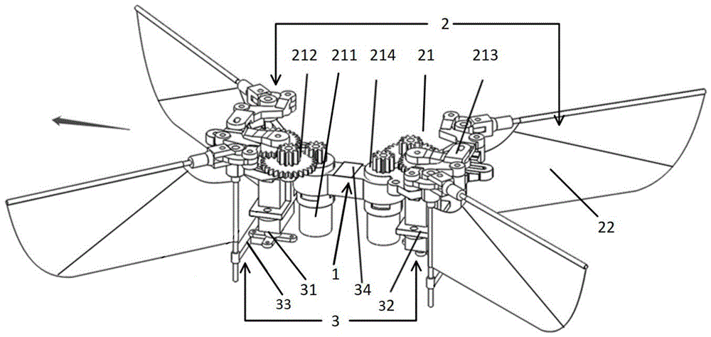
1-中间连接结构;2-扑翼系统;3-增稳控制系统;1-Intermediate connection structure; 2-Flap wing system; 3-Stability augmentation control system;
21-拍动机构;211-空心杯电机;212-减速齿轮组;213-拍动角放大机构;214-底座;21-beating mechanism; 211-hollow cup motor; 212-reduction gear set; 213-beating angle amplification mechanism; 214-base;
2121-主轴齿轮;2122-双层齿轮;2123-大齿轮;2124-驱动连杆安装孔;2121-Main shaft gear; 2122-Double-layer gear; 2123-Large gear; 2124-Drive connecting rod mounting hole;
2131-驱动连杆;2132-Z型连杆;2133-圆弧连杆;2134-摇杆;2131-drive connecting rod; 2132-Z-type connecting rod; 2133-arc connecting rod; 2134-rocker;
2141-电机安装孔;2142-双层齿轮安装孔;2143-大齿轮安装孔;2144-Z型连杆安装孔;2145-摇杆安装孔;2146-槽形凸台;2147-姿态控制舵机固定架安装孔;2141-Motor mounting hole; 2142-Double gear mounting hole; 2143-Large gear mounting hole; 2144-Z-type connecting rod mounting hole; 2145-Rocker mounting hole; 2146-Slotted boss; 2147-Attitude control servo Mounting hole for fixing frame;
22-扑翼;221-翼膜;222-主翼杆;223-辅翼杆;224-翼根杆;22 - flapping wing; 221 - wing membrane; 222 - main wing rod; 223 - auxiliary wing rod; 224 - wing root rod;
31-姿态控制舵机;31 - Attitude control steering gear;
32-姿态控制舵机固定架;321-底座安装孔;322-姿态控制舵机安装孔;32 - Attitude control servo mounting bracket; 321 - Base mounting hole; 322 - Attitude control servo mounting hole;
33-翼根位置控制机构;331-翼根定位孔;332-姿态控制舵机摇臂连接槽;33-wing root position control mechanism; 331-wing root positioning hole; 332-attitude control steering gear rocker arm connecting slot;
34-飞行控制电路板;34 - flight control circuit board;
具体实施方式Detailed ways
下面将结合附图和实施例对本发明作进一步的详细说明。The present invention will be further described in detail below in conjunction with the accompanying drawings and embodiments.
如图1所示,本发明一种可自主增稳控制的微型双扑翼飞行器,包含中间连接结构1、扑翼系统2以及增稳控制系统3。箭头指向前方。As shown in FIG. 1 , a miniature dual flapping-wing aircraft capable of autonomous stabilization control of the present invention includes an intermediate connection structure 1 , a flapping wing system 2 and a stabilization
如图2所示,所述中间连接结构1为立体结构,上部前后两端开有两孔,用于固定前后两套拍动机构21,以将两套拍动机构21组合为一个整体。As shown in FIG. 2 , the intermediate connection structure 1 is a three-dimensional structure, and two holes are opened at the front and rear ends of the upper part for fixing the front and rear two sets of flapping
如图1所示,所述扑翼系统2共有两套,每套均包括拍动机构21及扑翼22。As shown in FIG. 1 , there are two sets of the flapping wing system 2 , and each set includes a
如图1所示,所述拍动机构21包括空心杯电机211、减速齿轮组212、拍动角放大机构213及底座214。所述空心杯电机211为大功率有刷电机。As shown in FIG. 1 , the
如图3所示,所述减速齿轮组212为二级直齿减速轮组,均采用塑料制成,包括主轴齿轮2121,双层齿轮2122和大齿轮2123。主轴齿轮2121安装在电机211的输出轴上,大齿轮2123安装在底座214中间的安装孔上,双层齿轮2122安装在底座两侧的任一安装孔上,分别与大齿轮2123和主轴齿轮2121啮合。空心杯电机211输出的高速旋转运动通过主轴齿轮2121依次带动双层齿轮2122、大齿轮2123实现减速。大齿轮2123上设有驱动连杆安装孔2124,用于安装拍动角放大机构的驱动连杆2131。As shown in FIG. 3 , the reduction gear set 212 is a secondary spur gear reduction gear set, all of which are made of plastic, including a
如图4所示,所述拍动角放大机构213为曲柄-连杆机构,包括驱动连杆2131、Z型连杆2132、圆弧连杆2133、摇杆2134。驱动连杆2131一端通过安装孔与大齿轮2123铰接,另一端在底座顶部的槽形凸台2146约束下滑动。Z型连杆2132两端分别设有一孔一槽,中上部设有一孔;Z型连杆2132通过中部的孔与底座214上缘内测两孔铰接,通过端部的孔与圆弧连杆2133任意端铰接,驱动连杆2131一端在槽内滑动。圆弧连杆2133两端开孔,分别与Z型连杆2132和摇杆2134铰接。摇杆2134中间设有一孔与圆弧连杆2133铰接,一端设有一孔与底座214上缘外侧两孔铰接,另一端沿轴向开孔固连主翼杆222。As shown in FIG. 4 , the flap
如图5所示,所述底座214呈对称布置。底座214最下端设定内径较大的柱形空腔电机安装孔2141,用于安装空心杯电机211;底座214中部设有三个孔及凸台2142、2143,分别用于双层齿轮2122和大齿轮2123的安装定位;底座214的上表面分布四个孔及凸台,用于安拍动角放大机构213;底座214上表面对称轴位置设置一个槽形凸台2146,用于拍动角放大机构213中驱动连杆2131的限位;底座214中部设两姿态控制舵机固定架安装孔2147,将姿态控制舵机固定架32固连在底座214上。As shown in FIG. 5 , the
如图6所示,所述扑翼22由翼膜221、主翼杆222、辅翼杆223、翼根杆224组成。翼膜221为柔性薄膜,通常采用聚乙烯材料等做成,呈仿生扑翼状。翼膜221前缘与主翼杆222连接,辅翼杆223与主翼杆222呈30°粘连在翼膜221上。翼膜221平铺状态下翼根杆224与翼膜221左侧粘连且与翼膜221前缘呈110°-120°,翼安装之后,翼根杆224与主翼杆222垂直,以便使翼膜221在安装后松弛。拍动过程中,主翼杆222带动辅翼杆223和翼膜221高频往复拍动,辅翼杆223和翼膜221在惯性力和气动力的作用下发生变形,膜的最大变形受翼根杆224位置的约束,使得上下拍中间时刻翼展向面积二阶矩位置处的攻角(定义为翼拍动平面与翼面积二阶矩位置处展向截面的夹角)在25°-35°之间,以维持较高的气动效率。所述扑翼系统2在上下拍中间时刻通过改变翼根杆224的前后左右位置,可改变翼膜221的张紧程度,进而改变上下拍攻角产生不同的气动力和气动力矩。As shown in FIG. 6 , the flapping
如图1所示,所述增稳控制系统3包含姿态控制舵机31及姿态控制舵机固定架32、翼根位置控制机构33及飞行控制电路板34。As shown in FIG. 1 , the
如图1所示,所述姿态控制舵机31为微小型大扭矩旋转舵机,一前一后分布在底座的正下方,通过舵机摇臂驱动翼根位置控制机构33左右移动,改变翼根杆224位置调整扑翼膜221上下拍时的张紧程度,在上下拍过程中产生非对称的气动力,从而获得气动控制力矩。As shown in FIG. 1 , the attitude
如图7所示,所述姿态控制舵机固定架32上端设两底座安装孔321,用于将姿态控制舵机固定架32与底座214固连;上端设两姿态控制舵机安装孔322,用于将姿态控制舵机31与姿态控制舵机固定架32固连。As shown in FIG. 7 , the upper end of the attitude control steering
如图8所示,所述翼根位置控制机构33呈T形,左右两个端点设翼根定位孔331孔约束翼根杆224,中间梁设姿态控制舵机摇臂连接槽332与姿态控制舵机31摇臂连接,从而实现将姿态控制舵机31的转动角转换为翼根位置控制机构33的左右移动,带动翼根杆224左右摆动,从而改变左右两侧扑翼翼膜221的张紧程度,产生左右翼不同的气动力,进而产生两组左右翼的升力差,因此两姿态控制舵机31反向转动能够产生滚转控制力矩,同向转动能够产生偏航控制力矩,二者叠加控制了飞行器的滚转和偏航。As shown in FIG. 8 , the wing root
所述飞行控制电路板34为采用MEMS工艺制造、微型、轻型的机载电路板,包含主控芯片和机载传感器,其中主控芯片为采用ARM Cortex-M内核的32位微控制器STM32F405,用于运行增稳控制算法,机载传感器采用微型九轴运动跟踪装置MPU9250,其中集成了加速度计、陀螺仪及磁力计,分别测量飞行器的加速度、角速度、磁方位角数据。机载传感器测量的数据经低通滤波处理后,在主控芯片中通过互补滤波和扩展卡尔曼滤波组成的姿态估计算法计算出飞行器的三轴角速度与三轴姿态角。为准确获取飞行器飞行参数,该飞行控制电路板34借助泡沫胶粘接在中间连接结构1上并靠近飞行器重心。The flight
当飞行器受到扰动时,将无扰动理想状态下的三轴姿态角控制指令作为姿态角期望值,姿态角期望值与飞行控制电路板34中的滤波算法解算出的三轴姿态角信息做差,差值作为姿态角控制器的输入值,经过外环PID控制,输出值直接作为三轴角速度期望值;之后,角速度期望值与飞行控制电路板34中的滤波算法解算出的三轴角速度信息做差,差值作为角速度控制器的输入值,经过内环PID控制,输出为三轴增稳控制期望;最后,三轴增稳控制期望通过预先设置的混控矩阵,转换为两个电机211与两个姿态控制舵机31这四个通道的PWM波控制信号,通过脉冲宽度的占空比来控制电机211的转速与姿态控制舵机31的舵偏量,进而产生三轴控制力矩,使飞行器快速做出相应动作,消除期望姿态与实际姿态间的误差,达到增稳控制的目的。When the aircraft is disturbed, the three-axis attitude angle control command in the undisturbed ideal state is taken as the expected value of the attitude angle, and the expected value of the attitude angle is compared with the three-axis attitude angle information calculated by the filtering algorithm in the flight
当飞行器需要右滚转力矩时,前端姿态控制舵机31摇臂顺时针转动,后端姿态控制舵机31摇臂逆时针转动,通过翼根位置控制机构33带动两对翼根杆224同时向右摆动,从而使左侧前后两个扑翼翼膜221的张紧程度同时变紧,攻角变大,升力增大;使右侧前后两个扑翼翼膜221的张紧程度同时放松,攻角变小,升力减小。因此产生了两组左右翼的升力差,得到右滚控制力矩,进而完成飞行器的右滚。左滚力矩姿态控制舵机31摇臂旋转方向与右滚转力矩产生过程相反。当飞行器需要产生抬头力矩时,前端电机211转速上升,后端电机211转速下降,前后两电机211分别驱动主轴齿轮2121及减速齿轮组212,经过拍动角放大机构213驱动扑翼22往复拍动,使得前对扑翼22拍动频率增高、升力增大,后对扑翼22拍动频率降低、升力减小,从而产生俯仰控制力矩,进而完成飞行器的抬头动作;低头力矩前后电机211转速的变化与抬头力矩相反。当飞行器需要产生左偏航力矩时,前后两个姿态控制舵机31同时顺时针转动,通过翼根位置控制机构33带动前端翼根杆224向右摆动、后端翼根杆224向左摆动:使左侧前后两个扑翼22上拍时翼膜221张紧程度变松、攻角变小、气动阻力增大,下拍时翼膜221张紧程度变紧、攻角变大、气动阻力减小;右侧前后两个扑翼22上拍时翼膜221的张紧程度变紧、攻角变大、气动阻力减小,下拍时翼膜221的张紧程度变松、攻角变小、气动阻力增大,因此在水平面内产生了两对扑翼22上下拍的阻力差,从而得到左偏航控制力矩,进而完成飞行器向左偏航。右偏航力矩姿态控制舵机31摇臂旋转方向与左偏航力矩产生过程相反。When the aircraft needs a right rolling torque, the front-end attitude
Claims (3)
Priority Applications (1)
| Application Number | Priority Date | Filing Date | Title |
|---|---|---|---|
| CN202010782988.7A CN112298552B (en) | 2020-08-06 | 2020-08-06 | A miniature dual flapping-wing aircraft capable of autonomous stability enhancement and control and its control torque generation method |
Applications Claiming Priority (1)
| Application Number | Priority Date | Filing Date | Title |
|---|---|---|---|
| CN202010782988.7A CN112298552B (en) | 2020-08-06 | 2020-08-06 | A miniature dual flapping-wing aircraft capable of autonomous stability enhancement and control and its control torque generation method |
Publications (2)
| Publication Number | Publication Date |
|---|---|
| CN112298552A CN112298552A (en) | 2021-02-02 |
| CN112298552B true CN112298552B (en) | 2022-08-12 |
Family
ID=74483622
Family Applications (1)
| Application Number | Title | Priority Date | Filing Date |
|---|---|---|---|
| CN202010782988.7A Active CN112298552B (en) | 2020-08-06 | 2020-08-06 | A miniature dual flapping-wing aircraft capable of autonomous stability enhancement and control and its control torque generation method |
Country Status (1)
| Country | Link |
|---|---|
| CN (1) | CN112298552B (en) |
Families Citing this family (8)
| Publication number | Priority date | Publication date | Assignee | Title |
|---|---|---|---|---|
| CN113341693B (en) * | 2021-06-08 | 2022-07-26 | 西北工业大学 | Course control method based on asymmetric phase difference and amplitude of flapping wings |
| CN113504722B (en) * | 2021-06-29 | 2022-08-12 | 上海交通大学 | Wing motion tracking control system, method, medium and device for flapping aircraft |
| CN114104283B (en) * | 2021-11-08 | 2024-06-25 | 北京航空航天大学 | Bionic micro flapping wing aircraft lift force and rolling moment control method |
| CN113844652B (en) * | 2021-11-08 | 2024-06-25 | 北京航空航天大学 | A bionic flapping-wing micro aircraft using tail-assisted control |
| CN114180055B (en) * | 2021-12-17 | 2024-08-09 | 北京航天测控技术有限公司 | Piezoelectric driving type miniature ornithopter and flight control method |
| CN114279446B (en) * | 2021-12-22 | 2023-11-03 | 广东汇天航空航天科技有限公司 | Aerocar navigation attitude measurement method and device and aerocar |
| CN114889821B (en) * | 2022-05-24 | 2023-02-24 | 深圳市人工智能与机器人研究院 | Four-wing flapping wing micro water surface aircraft and flight method |
| CN116674746B (en) * | 2023-06-07 | 2025-10-24 | 东南大学 | A simple aircraft device based on wing flapping trajectory attitude stabilization algorithm |
Family Cites Families (6)
| Publication number | Priority date | Publication date | Assignee | Title |
|---|---|---|---|---|
| JP2012529398A (en) * | 2009-06-05 | 2012-11-22 | エアロバイロメント | Aircraft flight mechanism and control method |
| CN106864750B (en) * | 2017-02-27 | 2019-04-26 | 北京航空航天大学 | A miniature link mechanism with controllable flip average position |
| CN109835481B (en) * | 2017-11-29 | 2021-09-28 | 中国科学院沈阳自动化研究所 | Flapping wing aircraft capable of controlling flight through wing surface deformation |
| CN110712751B (en) * | 2019-09-03 | 2020-12-22 | 北京航空航天大学 | Miniature four-flapping-wing aircraft |
| CN110703788A (en) * | 2019-10-16 | 2020-01-17 | 北京航空航天大学 | A Stability Augmentation Control Method for a Micro Flapping-Wing Aircraft and Its Implementation |
| CN111301677A (en) * | 2020-02-29 | 2020-06-19 | 南京航空航天大学 | Eight-wing flapping wing aircraft capable of hovering and flight control method thereof |
-
2020
- 2020-08-06 CN CN202010782988.7A patent/CN112298552B/en active Active
Also Published As
| Publication number | Publication date |
|---|---|
| CN112298552A (en) | 2021-02-02 |
Similar Documents
| Publication | Publication Date | Title |
|---|---|---|
| CN112298552B (en) | A miniature dual flapping-wing aircraft capable of autonomous stability enhancement and control and its control torque generation method | |
| CN112009683B (en) | A miniature double flapping aircraft | |
| CN112009682B (en) | Bionic flapping wing micro aircraft for realizing high control torque generation based on double-wing differential motion and steering engine gravity center change | |
| CN110203388A (en) | A kind of double flapping wing aircrafts of miniature imitative dragonfly | |
| CN204323687U (en) | A four-wing flapping-wing micro-aircraft | |
| CN110703788A (en) | A Stability Augmentation Control Method for a Micro Flapping-Wing Aircraft and Its Implementation | |
| CN113844652B (en) | A bionic flapping-wing micro aircraft using tail-assisted control | |
| CN108438220A (en) | A kind of multiple degrees of freedom imitates dragonfly flapping wing aircraft and its control method | |
| CN110525647B (en) | A transmission mechanism suitable for a miniature quadruple flapping aircraft | |
| CN110435888B (en) | Flapping wing aircraft | |
| CN113335521B (en) | High-maneuverability ornithopter type bionic bat aircraft with flexible structure and flight control method thereof | |
| CN112034868A (en) | A yaw control method and mechanism for a bionic micro flapping-wing aircraft | |
| CN116022332B (en) | A wire-driven beetle-like micro-flapping wing aircraft | |
| CN218198818U (en) | A fixed-wing unmanned aerial vehicle capable of vertical take-off and landing | |
| CN112009681B (en) | A bionic flapping-wing micro-aircraft with adjustable flap angle average position and its flight control method | |
| US12441468B2 (en) | Bio-inspired flapping wing/fin robotic platform | |
| CN208036606U (en) | A kind of imitative dragonfly flapping wing aircraft of multiple degrees of freedom | |
| CN115973414B (en) | A miniature flapping-wing aircraft based on cruciform tail control | |
| TWI572526B (en) | Miniature aircraft wings drive structure | |
| CN113911343B (en) | High-efficiency transmission flapping wing mechanism with rolling control function | |
| CN114104283B (en) | Bionic micro flapping wing aircraft lift force and rolling moment control method | |
| CN222247703U (en) | Bionic butterfly aircraft | |
| CN113859528A (en) | Dragonfly-like flapping wing aircraft | |
| CN118992145A (en) | Bionic butterfly mixed control wing flapping aircraft | |
| CN119142521A (en) | Bionic butterfly ornithopter with double driving structures |
Legal Events
| Date | Code | Title | Description |
|---|---|---|---|
| PB01 | Publication | ||
| PB01 | Publication | ||
| SE01 | Entry into force of request for substantive examination | ||
| SE01 | Entry into force of request for substantive examination | ||
| GR01 | Patent grant | ||
| GR01 | Patent grant |