CN112296821A - Abrasive belt type wire drawing processing device for plastic product surface machining - Google Patents
Abrasive belt type wire drawing processing device for plastic product surface machining Download PDFInfo
- Publication number
- CN112296821A CN112296821A CN202011143758.2A CN202011143758A CN112296821A CN 112296821 A CN112296821 A CN 112296821A CN 202011143758 A CN202011143758 A CN 202011143758A CN 112296821 A CN112296821 A CN 112296821A
- Authority
- CN
- China
- Prior art keywords
- mounting plate
- plastic product
- wire drawing
- abrasive belt
- sliding
- Prior art date
- Legal status (The legal status is an assumption and is not a legal conclusion. Google has not performed a legal analysis and makes no representation as to the accuracy of the status listed.)
- Pending
Links
Images


Classifications
-
- B—PERFORMING OPERATIONS; TRANSPORTING
- B24—GRINDING; POLISHING
- B24B—MACHINES, DEVICES, OR PROCESSES FOR GRINDING OR POLISHING; DRESSING OR CONDITIONING OF ABRADING SURFACES; FEEDING OF GRINDING, POLISHING, OR LAPPING AGENTS
- B24B21/00—Machines or devices using grinding or polishing belts; Accessories therefor
- B24B21/006—Machines or devices using grinding or polishing belts; Accessories therefor for special purposes, e.g. for television tubes, car bumpers
-
- B—PERFORMING OPERATIONS; TRANSPORTING
- B24—GRINDING; POLISHING
- B24B—MACHINES, DEVICES, OR PROCESSES FOR GRINDING OR POLISHING; DRESSING OR CONDITIONING OF ABRADING SURFACES; FEEDING OF GRINDING, POLISHING, OR LAPPING AGENTS
- B24B21/00—Machines or devices using grinding or polishing belts; Accessories therefor
- B24B21/18—Accessories
-
- B—PERFORMING OPERATIONS; TRANSPORTING
- B24—GRINDING; POLISHING
- B24B—MACHINES, DEVICES, OR PROCESSES FOR GRINDING OR POLISHING; DRESSING OR CONDITIONING OF ABRADING SURFACES; FEEDING OF GRINDING, POLISHING, OR LAPPING AGENTS
- B24B41/00—Component parts such as frames, beds, carriages, headstocks
- B24B41/02—Frames; Beds; Carriages
-
- B—PERFORMING OPERATIONS; TRANSPORTING
- B24—GRINDING; POLISHING
- B24B—MACHINES, DEVICES, OR PROCESSES FOR GRINDING OR POLISHING; DRESSING OR CONDITIONING OF ABRADING SURFACES; FEEDING OF GRINDING, POLISHING, OR LAPPING AGENTS
- B24B47/00—Drives or gearings; Equipment therefor
-
- B—PERFORMING OPERATIONS; TRANSPORTING
- B24—GRINDING; POLISHING
- B24B—MACHINES, DEVICES, OR PROCESSES FOR GRINDING OR POLISHING; DRESSING OR CONDITIONING OF ABRADING SURFACES; FEEDING OF GRINDING, POLISHING, OR LAPPING AGENTS
- B24B55/00—Safety devices for grinding or polishing machines; Accessories fitted to grinding or polishing machines for keeping tools or parts of the machine in good working condition
- B24B55/06—Dust extraction equipment on grinding or polishing machines
- B24B55/08—Dust extraction equipment on grinding or polishing machines specially designed for belt grinding machines
Abstract
The invention relates to a wire drawing treatment device, in particular to a wire drawing treatment device for abrasive belt type plastic product surface processing. The invention provides a wire drawing treatment device for abrasive belt type plastic product surface processing, which has simple steps, time and labor saving and high efficiency. A wire drawing processing device for abrasive belt type plastic product surface processing comprises: the top parts of the two support legs are connected with the mounting plate; the mounting plate is provided with a supporting plate; the mounting plate is provided with a wire drawing mechanism, and the wire drawing mechanism is connected with the supporting plate; the pressing mechanism is arranged on the mounting plate, and the wire drawing mechanism is matched with the pressing mechanism. According to the invention, the output shaft of the motor rotates to drive the right roller to rotate, the right roller rotates to drive the abrasive belt to rotate, the abrasive belt rotates to drive the left roller to rotate, and the abrasive belt performs wire drawing on the plastic product, so that the effect of automatic wire drawing treatment is achieved, and the device is time-saving, labor-saving and high in efficiency.
Description
Technical Field
The invention relates to a wire drawing treatment device, in particular to a wire drawing treatment device for abrasive belt type plastic product surface processing.
Background
The surface wire drawing is handled through grinding the product and forming the line on the workpiece surface, plays decorative effect's a surface treatment means, and in the course of working of plastic goods, people need carry out the wire drawing to plastic goods and handle, and traditional wire drawing technology is by artifical manual operation, and the step is loaded down with trivial details, and troublesome poeration, it is wasted time and energy, and the long-time work of workman can reduce wire drawing efficiency to can't satisfy the demand of factory large-scale production.
Patent application CN208483665U, published as 2019.02.12, discloses an imitative metal garrulous strip wire drawing device in abrasive band formula plastic products surface, including anchor clamps, a actuating mechanism, wire drawing mechanism and pushing down the mechanism etc. through a actuating mechanism drive anchor clamps and drive the plastic products removal, first motor passes through the action wheel and drives the abrasive band transmission, pushes down the mechanism and pushes down the abrasive band for abrasive band and plastic products surface contact and carry out the wire drawing, however the device can not clear up the waste material automatically.
Therefore, it is desired to design a wire drawing device for processing the surface of an abrasive belt type plastic product, which has simple steps, time saving, labor saving and high efficiency.
Disclosure of Invention
In order to overcome the defects of complicated manual wire drawing steps, time and labor waste and low efficiency, the invention has the technical problems that: provides a wire drawing processing device for abrasive belt type plastic product surface processing, which has simple steps, time and labor saving and high efficiency.
The technical implementation scheme of the invention is as follows: a wire drawing processing device for abrasive belt type plastic product surface processing comprises:
the top parts of the two support legs are connected with the mounting plate;
the mounting plate is provided with a supporting plate;
the mounting plate is provided with a wire drawing mechanism, and the wire drawing mechanism is connected with the supporting plate;
the pressing mechanism is arranged on the mounting plate, and the wire drawing mechanism is matched with the pressing mechanism.
More preferably, the wire drawing mechanism includes:
the motor is arranged on the supporting plate;
the mounting plate is provided with four brackets;
the two groups of opposite brackets are rotatably connected with a roller, and the roller close to one side of the supporting plate is connected with an output shaft of the motor;
the abrasive belt is wound on the two rollers and the pressing mechanism.
More preferably, the pressing mechanism includes:
the mounting plate is provided with a first support frame;
the first support frame is provided with a hollow pipe;
the telescopic pipe is arranged on the hollow pipe;
the top of the first spring is connected with the hollow pipe, and the bottom of the first spring is connected with the telescopic pipe;
the lower part of the telescopic pipe is provided with a connecting rod;
the rotating wheel is rotatably arranged on the inner side of the connecting rod and is matched with the abrasive belt.
More preferably, the method further comprises the following steps:
the mounting plate is provided with a material shifting mechanism;
the material poking mechanism comprises:
the mounting plate is provided with a discharging frame;
the mounting plate is provided with four second support frames;
the four second supporting frames are rotatably connected with the chain assembly;
the chain assembly is provided with two first connecting rods;
the lower parts of the two first connecting rods are rotatably connected with the shifting block;
two first torsion springs are wound on the upper portion of the shifting block, the inner side of each first torsion spring is connected with the shifting block, and the outer side of each first torsion spring is connected with the first connecting rod.
More preferably, the method further comprises the following steps:
the mounting plate is provided with a transmission mechanism, and the transmission mechanism is connected with the roller and the chain assembly at one side close to the supporting plate;
the transmission mechanism comprises:
the mounting plate is symmetrically provided with third support frames;
the lower part of the third support frame is rotatably provided with a rotating shaft which is connected with the chain assembly;
and a transmission component is connected between the rotating shaft and the roller close to one side of the supporting plate.
More preferably, the method further comprises the following steps:
the mounting plate is provided with a cleaning mechanism, and the cleaning mechanism is matched with the shifting block;
clearance mechanism including:
the mounting plate is provided with four sliding sleeves;
the sliding rods are connected between the inner sides of the four sliding sleeves in a sliding manner and are matched with the shifting blocks;
the sliding rod is wound with two second springs, one side of each second spring is connected with the sliding sleeve close to one side of the supporting plate, and the other side of each second spring is connected with the sliding rod;
the inner side of the upper part of the sliding rod is connected with a second connecting rod which is positioned above the mounting plate;
the second connecting rod is provided with two connecting sleeves;
the two connecting sleeves are respectively and rotatably provided with a hairbrush, the hairbrush is positioned above the mounting plate, and the two hairbrushes are mutually matched;
and the mounting plate is provided with two stop rods which are matched with the sliding rod.
More preferably, the method further comprises the following steps:
the mounting plate is provided with a rotating mechanism which is connected with the connecting sleeve and the hairbrush;
the rotating mechanism comprises:
gears are arranged at the lower parts of the two brushes;
the upper parts of the two brushes are wound with second torsion springs, one sides of the second torsion springs are connected with the connecting sleeve, and the other sides of the second torsion springs are connected with the gear;
the mounting plate is provided with four support columns;
the rack is connected to two adjacent support columns, and the gear is meshed with the rack.
More preferably, the material of the support post is an alloy.
Compared with the prior art, the invention has the following advantages:
1. according to the automatic wire drawing machine, the motor is started, the output shaft of the motor rotates to drive the right roller to rotate, the right roller rotates to drive the abrasive belt to rotate, the abrasive belt rotates to drive the left roller to rotate, the left and right rollers rotate to enable the abrasive belt to stably rotate, the abrasive belt performs wire drawing on plastic products, the effect of automatic wire drawing is achieved, and time, labor and efficiency are saved;
2. according to the automatic feeding device, the shifting block is matched with the mounting plate, when the shifting block moves leftwards in the mounting plate, the shifting block moves and pushes the plastic product at the bottommost in the discharging frame to move leftwards, after the plastic product at the bottommost moves out of the discharging frame, the rest plastic product in the discharging frame moves downwards due to gravity, and the shifting block moves to finally push the plastic product which is moved out of the discharging frame to a position between the mounting plate and the rotating wheel, so that the automatic feeding effect is achieved;
3. according to the invention, the abrasive belt is matched with the pressing mechanism, the abrasive belt rotates to drive the pressing mechanism to partially operate, and when a plastic product moves between the mounting plate and the pressing mechanism, the pressing mechanism completely operates and presses the plastic product, so that the plastic product is better drawn;
4. according to the invention, the slide rod moves to drive the second connecting rod to move rightwards, the second connecting rod moves to drive the connecting sleeve to move rightwards, so that the hairbrush moves rightwards, and after the hairbrush moves to contact a plastic product, the hairbrush cleans the surface of the plastic product, thereby achieving the effect of cleaning waste materials;
5. according to the invention, the gear is meshed with the rack, the rack enables the gear to rotate, the gear rotates to enable the hairbrush to rotate outwards, and the hairbrush pushes the waste at the top of the plastic product to the front side and the rear side of the left part of the top side of the mounting plate while rotating, so that people can conveniently clean the waste.
Drawings
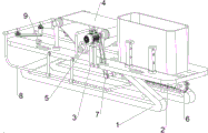
Fig. 1 is a schematic perspective view of the present invention.
Fig. 2 is a schematic perspective view of the wire drawing mechanism of the present invention.
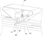
Fig. 3 is a schematic perspective view of the pressing mechanism according to the present invention.
Fig. 4 is a schematic perspective view of a first material pushing mechanism according to the present invention.
Fig. 5 is a schematic perspective view of a second material pushing mechanism according to the present invention.
Fig. 6 is a schematic perspective view of the transmission mechanism of the present invention.
Fig. 7 is a schematic perspective view of the cleaning mechanism of the present invention.
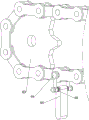
Fig. 8 is a schematic perspective view of the rotating mechanism of the present invention.
The meaning of the reference symbols in the figures: 1. the device comprises supporting legs, 2, a mounting plate, 3, a supporting plate, 4, a wire drawing mechanism, 41, a motor, 42, a support, 43, a roller, 44, an abrasive belt, 5, a pressing mechanism, 51, a first support frame, 52, a hollow pipe, 53, a telescopic pipe, 54, a first spring, 55, a connecting rod, 56, a rotating wheel, 6, a material stirring mechanism, 61, a material discharging frame, 62, a second support frame, 63, a chain component, 64, a first connecting rod, 65, a stirring block, 66, a first torsion spring, 7, a transmission mechanism, 71, a transmission component, 72, a third support frame, 73, a rotating shaft, 8, a cleaning mechanism, 81, a sliding sleeve, 82, a sliding rod, 83, a second spring, 84, a second connecting rod, 85, a connecting sleeve, 86, a brush, 87, a stop lever, 9, a rotating mechanism, 91, a gear, 92, a second torsion spring, 93, a support column, 94 and a rack.
Detailed Description
The technical solutions in the embodiments of the present invention will be clearly and completely described below, and it is obvious that the described embodiments are only a part of the embodiments of the present invention, and not all embodiments. All other embodiments, which can be derived by a person skilled in the art from the embodiments given herein without making any creative effort, shall fall within the protection scope of the present invention.
Example 1
The utility model provides a wire drawing processing apparatus is used in abrasive band formula plastic product surface machining, as shown in figure 1, figure 2, figure 6 and figure 7, including stabilizer blade 1, mounting panel 2, layer board 3, wire drawing mechanism 4 and pushing down mechanism 5, two 1 tops of stabilizer blade are connected with mounting panel 2, 2 front side middle parts of mounting panel are equipped with layer board 3, 2 tops of mounting panel are equipped with wire drawing mechanism 4, wire drawing mechanism 4 is connected with layer board 3, 2 tops of mounting panel are equipped with pushing down mechanism 5, wire drawing mechanism 4 and pushing down mechanism 5 cooperation.
The manual drawing step is tedious, time-consuming and labor-consuming and low in efficiency, the equipment can automatically draw the plastic product, the steps are simple, time-saving, labor-saving and high in efficiency, firstly, people put the plastic product on the right side of the top of the mounting plate 2 and move the plastic product to the left, people then operate the drawing mechanism 4, the drawing mechanism 4 operates to drive the pressing mechanism 5 to partially operate due to the matching of the drawing mechanism 4 and the pressing mechanism 5, when the plastic product moves between the mounting plate 2 and the pressing mechanism 5, the drawing mechanism 4 operates and starts to draw the plastic product, when the plastic product moves out from the space between the mounting plate 2 and the pressing mechanism 5, people stop moving the plastic product, the pressing mechanism 5 returns to partially operate, the plastic product is drawn, people take out the plastic product from the left side of the top of the mounting plate 2, and if people need to draw the plastic product, plastic products can be continuously placed on the right side of the top of the mounting plate 2 and move leftwards, if people finish the wire drawing work of the plastic products, the wire drawing mechanism 4 can stop running, after the pressing mechanism 5 stops running, waste materials on the top of the mounting plate 2 are cleaned, the plastic products which finish the wire drawing are collected, and if the equipment is used again, the steps are repeated.
Example 2
On the basis of embodiment 1, as shown in fig. 2, 3 and 6, the wire drawing mechanism 4 includes a motor 41, a bracket 42, a roller 43 and an abrasive belt 44, the motor 41 is installed on the top of the supporting plate 3, four brackets 42 are installed on the top of the mounting plate 2, the roller 43 is rotatably connected between the tops of the brackets 42 on the front and rear sides, the front side of the roller 43 on the right side is connected with an output shaft of the motor 41, and the abrasive belt 44 is wound between the rollers 43 on the left and right sides and the pressing mechanism 5.
When the plastic product is moved between the mounting plate 2 and the pressing mechanism 5, the pressing mechanism 5 completely operates and presses the plastic product, meanwhile, the abrasive belt 44 rotates and starts to draw wires, at the moment, the plastic product is continuously pushed leftwards, the abrasive belt 44 contacts with the plastic product and generates friction, because the plastic product has larger volume, the friction force is insufficient to move the plastic product, after the plastic product is moved out from between the mounting plate 2 and the pressing mechanism 5, people stop promoting plastic product, push down 5 mechanisms and resume for partial operation, plastic product has accomplished the wire drawing this moment, people take out plastic product from 2 top left sides of mounting panel again, if people still need carry out the wire drawing to plastic product, can continue to put plastic product on 2 top right sides of mounting panel, and make it move left, if people have accomplished plastic product's wire drawing work, can close motor 41, treat to push down 5 mechanisms behind the shut down, clear up the waste material at 2 tops of mounting panel, collect the plastic product of having accomplished the wire drawing again, if this equipment of reuse, it can to repeat above-mentioned step.
The pressing mechanism 5 comprises a first support frame 51, a hollow pipe 52, an extension pipe 53, a first spring 54, a connecting rod 55 and a rotating wheel 56, the first support frame 51 is arranged at the top of the mounting plate 2, the first support frame 51 is positioned between the supports 42 at the left side and the right side, the hollow pipe 52 is arranged in the middle of the bottom side of the first support frame 51, the extension pipe 53 is arranged at the bottom of the hollow pipe 52, the first spring 54 is wound on the extension pipe 53, the top of the first spring 54 is connected with the hollow pipe 52, the bottom of the first spring 54 is connected with the extension pipe 53, the connecting rod 55 is arranged at the lower part of the extension pipe 53, the rotating wheel 56 is rotatably arranged.
When the plastic product moves between the mounting plate 2 and the rotating wheel 56, the plastic product moves the rotating wheel 56 upwards to drive the connecting rod 55 to move upwards, the telescopic tube 53 is shortened, the first spring 54 is changed from the initial state to the compressed state, the elastic force presses the plastic product by the rotating wheel 56, the abrasive belt 44 starts to draw the plastic product, when the plastic product moves out from between the mounting plate 2 and the rotating wheel 56, the human stops pushing the plastic product, the first spring 54 is reset from the compressed state, the elastic force restores the telescopic tube 53 to the original length, the connecting rod 55 moves back downwards, and the rotating wheel 56 moves back downwards, at this moment, the plastic product is drawn, people take out the plastic product from the left side of the top of the mounting plate 2, if people need to draw the plastic product, the plastic product can be put on the right part of the top side of the mounting plate 2 continuously and moved leftwards, if people finish the drawing work of the plastic product, the motor 41 can be turned off, after the rotating wheel 56 stops rotating, the waste at the top of the mounting plate 2 is cleaned, the plastic product with the drawn wire is collected again, and if the equipment is used again, the steps are repeated.
Example 3
On the basis of the embodiment 2, as shown in fig. 4, 5, 6, 7 and 8, the material pulling device further includes a material pulling mechanism 6, the right portion of the mounting plate 2 is provided with the material pulling mechanism 6, the material pulling mechanism 6 includes a material placing frame 61, second support frames 62, chain assemblies 63, first connecting rods 64, pulling blocks 65 and first torsion springs 66, the right portion of the top side of the mounting plate 2 is provided with the material placing frame 61, the left and right portions of the right portion of the bottom side of the mounting plate 2 are provided with two second support frames 62, the chain assemblies 63 are rotatably connected between the four second support frames 62, the front and rear sides of each chain assembly 63 are provided with the first connecting rods 64, the pulling blocks 65 are rotatably connected between the lower portions of the first connecting rods 64 of the front and rear sides, the front and rear sides of the upper portions of the pulling blocks 65 are wound with the first torsion springs 66, the inner sides of the first torsion springs 66 are connected with the pulling blocks 65, and the.
People put a stack of plastic products in the material placing frame 61, then manually rotate the chain assembly 63 anticlockwise, the chain assembly 63 rotates to move the first connecting rod 64, then the shifting block 65 and the first torsion spring 66 move, when the shifting block 65 moves leftwards in the mounting plate 2, the shifting block 65 moves and pushes the plastic product at the bottommost in the material placing frame 61 to move leftwards, after the plastic product at the bottommost is moved out of the material placing frame 61, the residual plastic product in the material placing frame 61 moves downwards due to gravity, the shifting block 65 moves and finally pushes the first plastic product moved out of the material placing frame 61 to a position between the mounting plate 2 and the rotating wheel 56, meanwhile, people start the motor 41, when the shifting block 65 pushes the second plastic product out of the material placing frame 61, the second plastic product continues to move leftwards, after the second plastic product is contacted with the first plastic product, the shifting block 65 continues to push the second plastic product to move leftwards, therefore, a first plastic product is moved out from the position between the mounting plate 2 and the rotating wheel 56, the abrasive belt 44 performs wire drawing treatment on the first plastic product when the first plastic product moves leftwards between the mounting plate 2 and the rotating wheel 56, then people take out the plastic product after wire drawing from the left side of the top of the mounting plate 2, if people need to perform wire drawing on the plastic product, the plastic product can be continuously put into the material placing frame 61, if people finish the wire drawing work of the plastic product, the motor 41 can be closed and the chain assembly 63 stops rotating, after the rotating wheel 56 stops rotating and the shifting block 65 does not move any more, waste materials on the top of the mounting plate 2 are cleaned, the plastic product after wire drawing is finished is collected, and if the equipment is used again, the steps are repeated.
The automatic chain conveying device is characterized by further comprising a transmission mechanism 7, the transmission mechanism 7 is arranged on the bottom side of the mounting plate 2, the transmission mechanism 7 is connected with the right side roller 43 and the chain assembly 63, the transmission mechanism 7 comprises a transmission assembly 71, a third support frame 72 and a rotating shaft 73, the front side of the right portion of the bottom side of the mounting plate 2 is symmetrically provided with the third support frame 72, the lower portion of the third support frame 72 is rotatably provided with the rotating shaft 73, the rear side of the rotating shaft 73 is connected with the chain assembly 63, and the front side of the rotating shaft 73 is connected with the transmission.
When the cylinder 43 on the right side rotates, the cylinder 43 on the right side rotates to drive the transmission assembly 71 to rotate, so as to drive the rotating shaft 73 to rotate, the rotating shaft 73 rotates to drive the chain assembly 63 to rotate, so that the shifting block 65 moves, the shifting block 65 moves and pushes the plastic product between the mounting plate 2 and the rotating wheel 56, and if the equipment is used again, the steps are repeated.
The cleaning device comprises a cleaning mechanism 8, a cleaning mechanism 8 is arranged on a mounting plate 2, the cleaning mechanism 8 is matched with a shifting block 65, the cleaning mechanism 8 comprises a sliding sleeve 81, a sliding rod 82, a second spring 83, a second connecting rod 84, a connecting sleeve 85, a brush 86 and a stop lever 87, two sliding sleeves 81 are arranged on the front side and the rear side of the mounting plate 2, the sliding sleeves 81 on the front side and the rear side are connected with the sliding rod 82 in a sliding mode, the sliding rod 82 is matched with the shifting block 65, the second spring 83 is wound on the front side and the rear side of the right part of the sliding rod 82, the left side of the second spring 83 is connected with the sliding sleeve 81 on the right side, the right side of the second spring 83 is connected with the sliding rod 82, the second connecting rod 84 is connected with the left inner side of the upper side of the sliding rod 82, the second connecting rod 84 is positioned above the mounting plate 2, the two connecting sleeves 85, the front side and the rear side of the right part of the bottom side of the mounting plate 2 are both provided with a stop lever 87, and the stop levers 87 are matched with the slide bars 82.
When the shifting block 65 moves rightwards below the mounting plate 2, the plastic product moves out from between the mounting plate 2 and the rotating wheel 56, after the shifting block 65 moves to be in contact with the sliding rod 82, the shifting block 65 moves to simultaneously push the sliding rod 82, so that the sliding rod 82 slides rightwards in the sliding sleeve 81, the second spring 83 is changed from an initial state to a stretching state, the sliding rod 82 moves to drive the second connecting rod 84 to move rightwards, the second connecting rod 84 moves to drive the connecting sleeve 85 to move rightwards, so that the hairbrush 86 moves to move rightwards, after the hairbrush 86 moves to be in contact with the plastic product, the hairbrush 86 cleans the surface of the plastic product, when the sliding rod 82 moves to be in contact with the stop rod 87, the stop rod 87 stops the sliding rod 82 from moving rightwards, so that the shifting block 65 rotates, the first torsion spring 66 is changed from the initial state to a compression state, after the shifting block 65 is separated from the sliding rod 82, the first torsion, meanwhile, the second spring 83 is reset from the stretching state, the sliding rod 82 moves back to the original position through the elastic force, so that the second connecting rod 84 moves back to the original position, the connecting sleeve 85 moves back to the original position, finally the hairbrush 86 moves back to the original position, and people take out the cleaned plastic products, and if the equipment is used again, the steps are repeated.
Still including rotary mechanism 9, mounting panel 2 top side left part is equipped with rotary mechanism 9, rotary mechanism 9 is connected with adapter sleeve 85 and brush 86, rotary mechanism 9 is including gear 91, second torsion spring 92, support column 93 and rack 94, the brush 86 lower part of both sides all is equipped with gear 91 around, brush 86 upper portion of both sides all has around second torsion spring 92 around, second torsion spring 92 top is connected with adapter sleeve 85, second torsion spring 92 bottom is connected with gear 91, both sides all are equipped with two support columns 93 around mounting panel 2 top side left part, two support column 93 tops of both sides all are connected with rack 94 around, gear 91 and rack 94 meshing.
When the brush 86 moves to the right, the brush 86 drives the gear 91 and the second torsion spring 92 to move to the right, when the gear 91 moves to be meshed with the rack 94, the rack 94 rotates the gear 91, the second torsion spring 92 changes from the initial state to the compressed state, the gear 91 rotates the brush 86 to rotate outwards, the brush 86 pushes the waste material on the top of the plastic product to the front and rear sides of the top left part of the mounting plate 2 while rotating, when the rack 94 is separated from the gear 91, the second torsion spring 92 is reset from the compressed state, so that the gear 91 is returned to the original position, the brush 86 is returned to the original position, the brushes 86 on the front and rear sides are matched again, when the brush 86 moves to the left, the brush 86 moves to drive the gear 91 and the second torsion spring 92 to move to the left, when the gear 91 moves to be meshed with the rack 94, because the gear 91 is a one-way gear 91, the rack 94 allows the gear 91 to idle so that the brush 86 does not rotate, and after all plastic products are drawn, the waste at the top of the mounting plate 2 is cleaned again by people, and if the device is reused, the above steps are repeated.
The above description is only for the purpose of illustrating the preferred embodiments of the present invention and is not to be construed as limiting the invention, and any modifications, equivalents, improvements and the like that fall within the spirit and principle of the present invention are intended to be included therein.
Claims (8)
1. The utility model provides a wire drawing processing apparatus is used in sand belt plastic product surface machining which characterized in that, including:
the top parts of the two support legs (1) are connected with the mounting plate (2);
the supporting plate (3) is arranged on the mounting plate (2);
the wire drawing mechanism (4) is arranged on the mounting plate (2), and the wire drawing mechanism (4) is connected with the supporting plate (3);
the pressing mechanism (5) is arranged on the mounting plate (2), and the wire drawing mechanism (4) is matched with the pressing mechanism (5).
2. A drawing processing apparatus for sand belt type plastic product surface processing according to claim 1, wherein the drawing mechanism (4) comprises:
the motor (41) is installed on the supporting plate (3);
the mounting plate (2) is provided with four brackets (42);
the rotary drum (43) is rotatably connected between the two groups of opposite brackets (42), and the rotary drum (43) close to one side of the supporting plate (3) is connected with an output shaft of the motor (41);
the abrasive belt (44), the two rollers (43) and the pressing mechanism (5) are wound with the abrasive belt (44).
3. A drawing processing apparatus for sand belt type plastic product surface processing according to claim 1, wherein the pressing means (5) comprises:
the mounting plate (2) is provided with a first support frame (51);
the first support frame (51) is provided with a hollow pipe (52);
a telescopic pipe (53), wherein the hollow pipe (52) is provided with the telescopic pipe (53);
the first spring (54) is wound on the telescopic pipe (53), one side of the first spring (54) is connected with the hollow pipe (52), and the other side of the first spring (54) is connected with the telescopic pipe (53);
the lower part of the telescopic pipe (53) is provided with a connecting rod (55);
a rotating wheel (56) is rotatably arranged on the inner side of the connecting rod (55), and the rotating wheel (56) is matched with the abrasive belt (44).
4. The drawing processing apparatus for sand belt type plastic product surface processing according to claim 2 or 3, further comprising:
the material shifting mechanism (6) is arranged on the mounting plate (2);
the material poking mechanism (6) comprises:
the discharging frame (61) is arranged on the mounting plate (2);
the mounting plate (2) is provided with four second support frames (62);
the chain assembly (63) is rotatably connected among the four second supporting frames (62);
the chain assembly (63) is provided with two first connecting rods (64);
the lower parts of the two first connecting rods (64) are rotatably connected with the shifting block (65);
the upper part of the shifting block (65) is wound with two first torsion springs (66), the inner side of each first torsion spring (66) is connected with the shifting block (65), and the outer side of each first torsion spring (66) is connected with the first connecting rod (64).
5. The apparatus for drawing a strand of abrasive belt material for surface processing of plastic parts as claimed in claim 4, further comprising:
the transmission mechanism (7) is arranged on the mounting plate (2), and the transmission mechanism (7) is connected with the roller (43) and the chain assembly (63) on one side close to the supporting plate (3);
the transmission mechanism (7) comprises:
the third support frame (72) is symmetrically arranged on the mounting plate (2);
the lower part of the third support frame (72) is rotatably provided with a rotating shaft (73), and the rotating shaft (73) is connected with the chain assembly (63);
and a transmission assembly (71) is connected between the rotating shaft (73) and the roller (43) close to one side of the supporting plate (3).
6. The apparatus for drawing a strand of abrasive belt material for surface finishing a plastic part as claimed in claim 5, further comprising:
the cleaning mechanism (8) is arranged on the mounting plate (2), and the cleaning mechanism (8) is matched with the shifting block (65);
the cleaning mechanism (8) comprises:
the sliding sleeve (81), four sliding sleeves (81) are arranged on the mounting plate (2);
the sliding rods (82) are connected between the inner sides of the four sliding sleeves (81) in a sliding manner, and the sliding rods (82) are matched with the shifting block (65);
the sliding rod (82) is wound with two second springs (83), one side of each second spring (83) is connected with the sliding sleeve (81) close to one side of the supporting plate (3), and the other side of each second spring (83) is connected with the sliding rod (82);
the inner side of the upper part of the sliding rod (82) is connected with a second connecting rod (84), and the second connecting rod (84) is positioned above the mounting plate (2);
the second connecting rod (84) is provided with two connecting sleeves (85);
the two connecting sleeves (85) are respectively and rotatably provided with a brush (86), the brushes (86) are positioned above the mounting plate (2), and the two brushes (86) are matched with each other;
two stop rods (87) are arranged on the mounting plate (2), and the stop rods (87) are matched with the sliding rod (82).
7. The apparatus for drawing a strand of abrasive belt material for surface finishing a plastic part as claimed in claim 6, further comprising:
the rotating mechanism (9) is arranged on the mounting plate (2), and the rotating mechanism (9) is connected with the connecting sleeve (85) and the hairbrush (86);
the rotating mechanism (9) comprises:
the gears (91) are arranged at the lower parts of the two brushes (86);
the upper parts of the two brushes (86) are wound with second torsion springs (92), one side of each second torsion spring (92) is connected with the connecting sleeve (85), and the other side of each second torsion spring (92) is connected with the gear (91);
the mounting plate (2) is provided with four support columns (93);
the rack (94) is connected to two adjacent support columns (93), and the gear (91) is meshed with the rack (94).
8. A wiredrawing processing apparatus for sand belt type plastic product surface processing according to claim 7, characterized in that the material of the supporting pillar (93) is alloy.
Priority Applications (1)
| Application Number | Priority Date | Filing Date | Title |
|---|---|---|---|
| CN202011143758.2A CN112296821A (en) | 2020-10-23 | 2020-10-23 | Abrasive belt type wire drawing processing device for plastic product surface machining |
Applications Claiming Priority (1)
| Application Number | Priority Date | Filing Date | Title |
|---|---|---|---|
| CN202011143758.2A CN112296821A (en) | 2020-10-23 | 2020-10-23 | Abrasive belt type wire drawing processing device for plastic product surface machining |
Publications (1)
| Publication Number | Publication Date |
|---|---|
| CN112296821A true CN112296821A (en) | 2021-02-02 |
Family
ID=74327132
Family Applications (1)
| Application Number | Title | Priority Date | Filing Date |
|---|---|---|---|
| CN202011143758.2A Pending CN112296821A (en) | 2020-10-23 | 2020-10-23 | Abrasive belt type wire drawing processing device for plastic product surface machining |
Country Status (1)
| Country | Link |
|---|---|
| CN (1) | CN112296821A (en) |
Cited By (3)
| Publication number | Priority date | Publication date | Assignee | Title |
|---|---|---|---|---|
| CN113021142A (en) * | 2021-03-29 | 2021-06-25 | 胡建雄 | Brake pad polishing equipment for new energy automobile |
| CN115157085A (en) * | 2022-06-28 | 2022-10-11 | 宁波市登平自动化有限公司 | Electric heating faucet casing polishing equipment |
| CN115256147A (en) * | 2022-10-08 | 2022-11-01 | 江苏隆凯森机械科技有限公司 | Quick grinding device of surface for cascaded main shaft production |
Citations (8)
| Publication number | Priority date | Publication date | Assignee | Title |
|---|---|---|---|---|
| JPS59214557A (en) * | 1983-05-17 | 1984-12-04 | Takegawa Tekko Kk | Grinder for belt sander |
| DE8707974U1 (en) * | 1987-06-04 | 1987-08-13 | Weber, Georg, 8640 Kronach, De | |
| CN2860628Y (en) * | 2005-12-14 | 2007-01-24 | 湖州德马物流系统工程有限公司 | Material mover of mechanism sorter |
| CN104608030A (en) * | 2015-02-06 | 2015-05-13 | 成都陶玛斯卫浴有限责任公司 | Device capable of improving wiredrawing stability |
| CN105598796A (en) * | 2016-03-17 | 2016-05-25 | 余晓娜 | Wiredrawing, polishing and grinding system for metal plates |
| CN205734296U (en) * | 2016-05-17 | 2016-11-30 | 赣州恒永铝材有限公司 | A kind of flat board aluminum profile extrusion wire-drawing frame |
| CN108622635A (en) * | 2018-05-14 | 2018-10-09 | 合肥智慧龙图腾知识产权股份有限公司 | A kind of feeding conveyer belt surface-cleaning device |
| CN208483665U (en) * | 2018-03-16 | 2019-02-12 | 东莞市万协塑胶科技有限公司 | Imitate metal fringe wire-drawing frame in a kind of abrasive belt plasthetics surface |
-
2020
- 2020-10-23 CN CN202011143758.2A patent/CN112296821A/en active Pending
Patent Citations (8)
| Publication number | Priority date | Publication date | Assignee | Title |
|---|---|---|---|---|
| JPS59214557A (en) * | 1983-05-17 | 1984-12-04 | Takegawa Tekko Kk | Grinder for belt sander |
| DE8707974U1 (en) * | 1987-06-04 | 1987-08-13 | Weber, Georg, 8640 Kronach, De | |
| CN2860628Y (en) * | 2005-12-14 | 2007-01-24 | 湖州德马物流系统工程有限公司 | Material mover of mechanism sorter |
| CN104608030A (en) * | 2015-02-06 | 2015-05-13 | 成都陶玛斯卫浴有限责任公司 | Device capable of improving wiredrawing stability |
| CN105598796A (en) * | 2016-03-17 | 2016-05-25 | 余晓娜 | Wiredrawing, polishing and grinding system for metal plates |
| CN205734296U (en) * | 2016-05-17 | 2016-11-30 | 赣州恒永铝材有限公司 | A kind of flat board aluminum profile extrusion wire-drawing frame |
| CN208483665U (en) * | 2018-03-16 | 2019-02-12 | 东莞市万协塑胶科技有限公司 | Imitate metal fringe wire-drawing frame in a kind of abrasive belt plasthetics surface |
| CN108622635A (en) * | 2018-05-14 | 2018-10-09 | 合肥智慧龙图腾知识产权股份有限公司 | A kind of feeding conveyer belt surface-cleaning device |
Cited By (5)
| Publication number | Priority date | Publication date | Assignee | Title |
|---|---|---|---|---|
| CN113021142A (en) * | 2021-03-29 | 2021-06-25 | 胡建雄 | Brake pad polishing equipment for new energy automobile |
| CN113021142B (en) * | 2021-03-29 | 2023-11-03 | 烟台成宇汽车部件有限公司 | Brake block equipment of polishing for new energy automobile |
| CN115157085A (en) * | 2022-06-28 | 2022-10-11 | 宁波市登平自动化有限公司 | Electric heating faucet casing polishing equipment |
| CN115157085B (en) * | 2022-06-28 | 2023-12-08 | 宁波市登平自动化有限公司 | Electric heating faucet shell polishing equipment |
| CN115256147A (en) * | 2022-10-08 | 2022-11-01 | 江苏隆凯森机械科技有限公司 | Quick grinding device of surface for cascaded main shaft production |
Similar Documents
| Publication | Publication Date | Title |
|---|---|---|
| CN112296821A (en) | Abrasive belt type wire drawing processing device for plastic product surface machining | |
| CN112092026B (en) | Equipment for punching plastic pipe | |
| CN113059056B (en) | Special-shaped steel pipe processingequipment for municipal administration building materials | |
| CN108274366B (en) | Building frame building steel pipe rust removal device | |
| CN112605874B (en) | Cylindrical metal polishing equipment for industrial production | |
| CN111570458A (en) | Auxiliary cleaning device for paint bucket | |
| CN112400938A (en) | Surface printing device for moon cake processing | |
| CN217224962U (en) | Special tool for polishing surface of pipe | |
| CN111889298B (en) | Wood grain manufacturing installation for furniture decoration | |
| CN113043476B (en) | Ceramic tile drilling equipment with adjustable building materials | |
| CN114178396B (en) | Fixed point punching equipment for manufacturing high-end equipment | |
| CN214720116U (en) | Portable reinforcing bar device of buckling for construction | |
| CN212334200U (en) | Cloth spreading machine with ironing function | |
| CN210816366U (en) | Through type piston rod belt cleaning device | |
| CN111940219B (en) | Novel painting machine | |
| CN111923298B (en) | Automobile tire skin scraping device | |
| CN219274107U (en) | Flat plate correction device | |
| CN111054807A (en) | Automatic production line for stamping of automobile covering parts | |
| CN216832986U (en) | Knurling device for ornament production for preventing ornament deformation | |
| CN111976013B (en) | Fish bowl antique device for stone carving industry | |
| CN215628780U (en) | Blanket embossing device | |
| CN218873024U (en) | Steel processing iron fillings belt cleaning device | |
| CN112974159B (en) | Automatic chopstick paint drawing equipment for tableware production | |
| CN117181872B (en) | Bending die for metal furniture parts | |
| CN218175363U (en) | A arrangement setting device for grey cloth |
Legal Events
| Date | Code | Title | Description |
|---|---|---|---|
| PB01 | Publication | ||
| PB01 | Publication | ||
| SE01 | Entry into force of request for substantive examination | ||
| SE01 | Entry into force of request for substantive examination | ||
| WD01 | Invention patent application deemed withdrawn after publication |
Application publication date: 20210202 |
|
| WD01 | Invention patent application deemed withdrawn after publication |