CN112290811B - Three-level converter, power conversion device and zero-sequence current suppression method - Google Patents
Three-level converter, power conversion device and zero-sequence current suppression method Download PDFInfo
- Publication number
- CN112290811B CN112290811B CN202011127858.6A CN202011127858A CN112290811B CN 112290811 B CN112290811 B CN 112290811B CN 202011127858 A CN202011127858 A CN 202011127858A CN 112290811 B CN112290811 B CN 112290811B
- Authority
- CN
- China
- Prior art keywords
- current
- output end
- converter
- direct current
- zero sequence
- Prior art date
- Legal status (The legal status is an assumption and is not a legal conclusion. Google has not performed a legal analysis and makes no representation as to the accuracy of the status listed.)
- Active
Links
Images


Classifications
-
- H—ELECTRICITY
- H02—GENERATION; CONVERSION OR DISTRIBUTION OF ELECTRIC POWER
- H02M—APPARATUS FOR CONVERSION BETWEEN AC AND AC, BETWEEN AC AND DC, OR BETWEEN DC AND DC, AND FOR USE WITH MAINS OR SIMILAR POWER SUPPLY SYSTEMS; CONVERSION OF DC OR AC INPUT POWER INTO SURGE OUTPUT POWER; CONTROL OR REGULATION THEREOF
- H02M7/00—Conversion of ac power input into dc power output; Conversion of dc power input into ac power output
- H02M7/02—Conversion of ac power input into dc power output without possibility of reversal
- H02M7/04—Conversion of ac power input into dc power output without possibility of reversal by static converters
-
- H—ELECTRICITY
- H02—GENERATION; CONVERSION OR DISTRIBUTION OF ELECTRIC POWER
- H02M—APPARATUS FOR CONVERSION BETWEEN AC AND AC, BETWEEN AC AND DC, OR BETWEEN DC AND DC, AND FOR USE WITH MAINS OR SIMILAR POWER SUPPLY SYSTEMS; CONVERSION OF DC OR AC INPUT POWER INTO SURGE OUTPUT POWER; CONTROL OR REGULATION THEREOF
- H02M1/00—Details of apparatus for conversion
- H02M1/0003—Details of control, feedback or regulation circuits
- H02M1/0038—Circuits or arrangements for suppressing, e.g. by masking incorrect turn-on or turn-off signals, e.g. due to current spikes in current mode control
-
- H—ELECTRICITY
- H02—GENERATION; CONVERSION OR DISTRIBUTION OF ELECTRIC POWER
- H02M—APPARATUS FOR CONVERSION BETWEEN AC AND AC, BETWEEN AC AND DC, OR BETWEEN DC AND DC, AND FOR USE WITH MAINS OR SIMILAR POWER SUPPLY SYSTEMS; CONVERSION OF DC OR AC INPUT POWER INTO SURGE OUTPUT POWER; CONTROL OR REGULATION THEREOF
- H02M1/00—Details of apparatus for conversion
- H02M1/0067—Converter structures employing plural converter units, other than for parallel operation of the units on a single load
- H02M1/0077—Plural converter units whose outputs are connected in series
Landscapes
- Engineering & Computer Science (AREA)
- Power Engineering (AREA)
- Inverter Devices (AREA)
Abstract
The invention discloses a three-level converter, a power conversion device and a zero sequence current suppression method, wherein the three-level converter comprises N two-level converters; each two-level converter comprises an alternating current input end, a first direct current output end and a second direct current output end, wherein the potential value of the first direct current output end is larger than that of the second direct current output end; a first direct current output end of the first converter is used as a first output end; a second direct current output end of the Nth converter is used as a second output end; and the second direct current output end of the two-level converter with a higher relative voltage value to the ground in any two adjacent two-level converters is connected with the first direct current output end of the two-level converter with a lower relative voltage value to the ground. N is an even number larger than 1, and the N/2 serial output end is used as a direct current median end. The three-level converter comprises a direct current neutral terminal with controllable relative potential, and zero-sequence current suppression is realized by controlling the output potential value of the direct current neutral terminal.
Description
Technical Field
The invention relates to the technical field of electric power, in particular to a three-level converter, an electric power conversion device and a zero sequence current suppression method.
Background
Along with the continuous rising of power grade of power generation equipment, the mode that 2 ~ 3 converters of equipment producer mostly adopt and connect in parallel operation improves equipment total power grade. The zero-drift sampling and pulse width modulation modes in the power generation equipment can cause the problems of overlarge zero-sequence (common-mode) current of the converter, oscillation and even out of control. Because zero sequence current does not produce active power but the current actually exists, the loss of the equipment is increased, and the efficiency of the equipment is reduced. The three-level converter comprises a potential neutral point in the topology, and the relative potential is controllable, so that the zero-sequence current can be effectively controlled. However, the disadvantages of the three-level converter are also very obvious, and the problems of excessive number of power switching tubes, complex modulation algorithm, more circuit power devices and the like exist. The two-level converter generally adds a magnetic loop to the cable to suppress the zero-sequence current, resulting in increased cost.
Disclosure of Invention
The invention provides a three-level converter, a power conversion device and a zero-sequence current suppression method, aiming at overcoming the defects of serious zero-sequence current between converter equipment and high cost of suppressing the zero-sequence current caused by parallel connection of two-level converters in the prior art.
The invention solves the technical problems through the following technical scheme:
a three-level converter comprises a first output end, a second output end and a direct current neutral end, and also comprises N two-level converters;
each two-level converter comprises an alternating current input end, a first direct current output end and a second direct current output end, wherein the potential value of the first direct current output end is greater than that of the second direct current output end;
n two-level current transformers are arranged from a first current transformer to an Nth current transformer from high to low according to the relative voltage value to the ground;
a first direct current output end of the first converter is used as the first output end;
a second direct current output end of the Nth converter is used as the second output end;
from the first converter to the Nth converter, the second DC output terminal of the two-level converter with higher relative voltage to ground in any two adjacent two-level converters is connected with the first DC output terminal of the two-level converter with lower relative voltage to ground to form a first series output terminal to an N-1 th series output terminal;
n is an even number larger than 1, and the N/2 serial output end is used as the direct current median end;
or the like, or, alternatively,
n is an odd number larger than 1, and the three-level converter further comprises a first capacitor and a second capacitor; one end of the first capacitor is connected with the (N-1)/2 th series output end, the other end of the first capacitor is connected with one end of the second capacitor, and the other end of the second capacitor is connected with the (N +1)/2 th series output end; and the connection point of the first capacitor and the second capacitor is used as the direct current neutral terminal.
In the scheme, the power topological structures of the two existing two-level converters are changed in the mode, the three-level converter is designed under the conditions that the alternating-current rated voltage is not changed and the quantity of the power switching tubes is not changed, the three-level converter comprises a neutral point with controllable relative potential, namely a direct-current neutral end, the zero-sequence (common-mode) current can be effectively controlled, the quantity of the power switching tubes is saved, and the control process is simplified.
Preferably, N is equal to 2;
the two-level converters are arranged according to the relative voltage value to the ground to form a first converter and a second converter;
a first direct current output end of the first converter is used as the first output end;
a second direct current output end of the second converter is used as the second output end;
the second direct current output end of the first converter is electrically connected with the first direct current output end of the second converter to form a first series output end;
the first series output end is used as the direct current median end.
In the scheme, a three-level converter is designed by using the power topological structure of two existing two-level converters under the conditions that the AC rated voltage is not changed and the quantity of power switching tubes is not changed, and the three-level converter comprises a neutral point with controllable relative potential, namely a DC neutral terminal, so that zero-sequence (common-mode) current can be effectively controlled, the quantity of the power switching tubes is saved, and the control process is simplified.
Preferably, N is equal to 3;
the three two-level converters are arranged according to the relative voltage value to the ground to form a third converter, a fourth converter and a fifth converter;
a first direct current output end of the third converter is used as the first output end;
a second direct current output end of the fifth converter is used as the second output end;
the second direct current output end of the third converter is connected with the first direct current output end of the fourth converter to form the first series output end;
the second direct current output end of the fourth converter is connected with the first direct current output end of the fifth converter to form a second series output end;
one end of the first capacitor is connected with the first series output end, the other end of the first capacitor is connected with one end of the second capacitor, and the other end of the second capacitor is connected with the second series output end;
and the connection point of the first capacitor and the second capacitor is used as the direct current neutral terminal.
In the scheme, by modifying the existing power topological structure of three two-level converters, a three-level converter is designed under the conditions that the AC rated voltage is not changed and the quantity of power switching tubes is not changed, the three-level converter comprises a neutral point with controllable relative potential, namely a DC neutral terminal, and can effectively control zero-sequence (common-mode) current, so that the quantity of the power switching tubes is saved, and the control process is simplified.
A power conversion device comprises a control module, at least one three-level converter and N grid-side converters, wherein one two-level converter corresponds to one grid-side converter; the alternating current input end is electrically coupled to an output end of a generator, and the first output end, the second output end, the first series output end to the (N-1) th series output end are respectively and electrically coupled to a direct current input end of the corresponding grid-side converter; the direct current neutral potential end is electrically coupled to a first neutral potential end of the generator;
the control module is used for generating a control signal based on the collected zero sequence current signal in the power conversion device so as to control the output voltage value of the direct current neutral terminal and inhibit the zero sequence current.
In the scheme, the power conversion device realizes zero sequence current suppression by using the three-level converter and controlling the output voltage value of the direct current neutral terminal, saves a common mode magnetic ring and reduces material cost compared with the existing realization mode that a magnetic ring is added on a cable of a two-level converter to suppress zero sequence current.
Preferably, the zero sequence current signal is a zero sequence component calculated from the current at the ac input terminal.
In the scheme, the current of the alternating current input end in the power conversion device is collected, the control signal is generated to control the output voltage value of the direct current neutral end so as to inhibit the zero sequence current, an additional signal sampling circuit is not needed, and the circuit design is simplified.
Preferably, the power conversion apparatus further includes a first current sampling module;
the first current sampling module is electrically coupled between the first neutral potential end and the direct current neutral potential end;
the zero sequence current signal is a zero sequence component generated by calculating the first sampling current of the first current sampling module.
In the scheme, the first current sampling module is added between the direct current neutral potential end of the three-level converter and the first neutral potential end of the generator, and the control signal is generated based on the first sampling current to control the output voltage value of the direct current neutral potential end so as to inhibit the zero sequence current, so that the accuracy of zero sequence current inhibition is improved, the problem of the current of a motor shaft is solved, the heat and current loss of the power conversion device are reduced, and the stability and controllability of the power conversion device are improved.
Preferably, the power conversion apparatus further includes a second current sampling module;
the output end of the grid-side converter is connected with the input end of the transformer;
the second current sampling module is electrically coupled between the direct current neutral potential end and a second neutral potential end of the transformer;
the zero sequence current signal is a zero sequence component generated by calculating the second sampling current of the second current sampling module.
In the scheme, the second current sampling module is arranged between the output end of the grid-side converter and the input end of the transformer, so that the zero-sequence current of the grid-side converter can be effectively inhibited when exceeding the standard.
Preferably, the power conversion apparatus further includes a first impedance circuit;
the first impedance circuit is electrically coupled between the first neutral potential terminal and the DC neutral potential terminal.
In the scheme, the first impedance circuit is arranged in the first current sampling circuit, so that the sampling accuracy of the sampling current is improved.
Preferably, the power conversion apparatus further includes a second impedance circuit;
the second impedance circuit is electrically coupled between the DC neutral potential terminal and the second neutral potential terminal.
In the scheme, the second impedance circuit is arranged in the second current sampling circuit, so that the sampling accuracy of the second current sampling circuit is improved.
A zero-sequence current suppression method applied to the power conversion apparatus described above, the zero-sequence current suppression method comprising:
acquiring the zero sequence current signal;
and generating the control signal based on the zero sequence current signal to control the output voltage value of the direct current neutral terminal to inhibit the zero sequence current.
In the scheme, the zero sequence current signal in the power conversion device is obtained, and the control signal is generated based on the zero sequence current signal to control the output voltage value of the direct current neutral terminal, so that zero sequence current suppression is realized, a common mode magnetic ring is saved compared with the existing realization mode, and the material cost is reduced.
Preferably, the current at the alternating current input end comprises three-phase input currents of a plurality of two-level current transformers;
the zero-sequence current signal is a zero-sequence component generated by calculating the three-phase input current;
the step of obtaining the zero sequence current signal comprises:
acquiring the three-phase input current;
the step of generating the control signal to control the output voltage value of the dc neutral terminal to suppress the zero sequence current based on the zero sequence current signal comprises:
adding a plurality of three-phase input currents to obtain the zero-sequence current;
judging whether the zero sequence current exceeds a threshold value;
and if so, outputting the control signal to the three-level converter to control and increase the output voltage value of the direct current neutral terminal so as to inhibit the zero sequence current.
In the scheme, the current of the alternating current input end in the power conversion device is collected, the control signal is generated to control the output voltage value of the direct current neutral end so as to inhibit the zero sequence current, an additional signal sampling circuit is not needed, and the circuit design is simplified.
Preferably, the power conversion apparatus further includes a first current sampling module;
the first current sampling module is electrically coupled between the first neutral potential end and the direct current neutral potential end;
the zero-sequence current signal is a zero-sequence component generated by calculating the sampling current of the first current sampling module;
the step of obtaining the zero sequence current signal comprises:
acquiring a sampling current of the first current sampling module;
the step of generating the control signal to control the output voltage value of the dc neutral terminal to suppress the zero sequence current based on the zero sequence current signal comprises:
and generating a control signal based on the sampling current to control the output voltage value of the direct current neutral terminal so as to inhibit the zero sequence current.
In the scheme, the first current sampling module is added between the direct current neutral potential end of the three-level converter and the first neutral potential end of the generator, and the control signal is generated based on the sampling current to control the output voltage value of the direct current neutral potential end so as to suppress the zero sequence current, so that the accuracy of suppressing the zero sequence current is improved, the problem of the current of a motor shaft is solved, the heat and current loss of the power conversion device are reduced, and the stability and controllability of the power conversion device are improved.
Preferably, the power conversion apparatus further includes a second current sampling module;
the output end of the grid-side converter is connected with the input end of the transformer;
the second current sampling module is electrically coupled between the direct current neutral potential end and a second neutral potential end of the transformer;
the zero-sequence current signal is a zero-sequence component generated by calculating a second sampling current of the second current sampling module;
the step of obtaining the zero sequence current signal comprises:
acquiring a second sampling current of the second current sampling module;
the step of generating the control signal to control the output voltage value of the dc neutral terminal to suppress the zero sequence current based on the zero sequence current signal comprises:
and generating a control signal based on the second sampling current to control the output voltage value of the direct current neutral terminal to inhibit the zero sequence current.
In the scheme, the second current sampling module is arranged between the output end of the grid-side converter and the input end of the transformer, so that the zero-sequence current of the grid-side converter can be effectively inhibited when exceeding the standard.
The positive progress effects of the invention are as follows: the three-level converter is designed under the conditions that the rated AC voltage is not changed and the number of the power switching tubes is not changed by changing the power topological structures of the two-level converters, and comprises a neutral point with controllable relative potential, namely a DC neutral end, so that zero-sequence (common-mode) current can be effectively controlled, the number of the power switching tubes is saved, and the control process is simplified; furthermore, the power conversion device using the three-level converter realizes zero sequence current suppression by controlling the output voltage value of the DC neutral terminal, saves a common mode magnetic ring compared with the existing realization mode, and reduces the material cost; the problem of motor shaft current is further solved, the heating and current loss of the power conversion device are reduced, the influence of zero sequence current on the power conversion device is reduced, and the stability and controllability of the power conversion device are improved.
Drawings
Fig. 1 is a schematic structural diagram of a three-level converter according to embodiment 1 of the present invention.
Fig. 2 is a schematic structural diagram of a three-level converter including two-level converters according to embodiment 1 of the present invention.
Fig. 3 is a schematic structural diagram of a three-level converter according to embodiment 2 of the present invention.
Fig. 4 is a schematic structural diagram of a three-level converter including three two-level converters according to embodiment 2 of the present invention.
Fig. 5 is a schematic configuration diagram of a power conversion device according to embodiment 3 of the present invention.
Fig. 6 is a schematic configuration diagram of a power conversion device according to embodiment 4 of the present invention.
Fig. 7 is a schematic flow chart of a zero sequence current suppression method according to embodiment 5 of the present invention.
Fig. 8 is a schematic flow chart of a zero sequence current suppression method according to embodiment 5 of the present invention.
Fig. 9 is a schematic flow chart of a zero sequence current suppression method according to embodiment 5 of the present invention.
Fig. 10 is a schematic flow chart of a zero sequence current suppression method according to embodiment 5 of the present invention.
Detailed Description
The invention is further illustrated by the following examples, which are not intended to limit the scope of the invention.
Example 1
The invention provides a three-level converter, which comprises a first output end, a second output end and a direct current neutral end, and also comprises N two-level converters;
each two-level converter comprises an alternating current input end, a first direct current output end and a second direct current output end, wherein the potential value of the first direct current output end is larger than that of the second direct current output end;
n two-level converters are arranged from a first converter to an Nth converter according to the relative voltage value to the ground;
a first direct current output end of the first converter is used as a first output end of the three-level converter;
a second direct current output end of the Nth converter is used as a second output end of the three-level converter;
from the first converter to the Nth converter, the second direct current output end of the two-level converter with higher relative voltage value to the ground in any two adjacent two-level converters is connected with the first direct current output end of the two-level converter with lower relative voltage value to the ground,
as shown in fig. 1, N is an even number greater than 1;
a second direct current output end of the 1 st _1 converter is connected with a first direct current output end of the 1 st _2 converter to form a first series output end;
the second direct current output end of the 1 st _ N/2 th converter is connected with the first direct current output end of the 1 st (N/2+1) th converter to form an N/2 th series output end;
a second direct current output end of the 1 st _ N-1 converter is connected with a first direct current output end of the 1 st _ N converter to form an N-1 th series output end;
and the N/2 serial output end is used as a direct current neutral end of the three-level converter.
As shown in fig. 2, the three-level converter N in this embodiment takes 2, that is, includes two-level converters;
the two-level converters are arranged according to the relative voltage value to the ground to form a 2_1 converter 1 and a 2_2 converter 2;
a first direct current output end of the 2_1 converter 1 is used as a first output end of the three-level converter;
a second direct current output end of the 2 nd-2 nd converter 2 is used as a second output end of the three-level converter;
the second direct current output end of the 2_1 converter 1 is electrically connected with the first direct current output end of the 2_2 converter 2 to form a first series output end;
the first series output end is used as a direct current neutral end of the three-level converter.
The three-level converter of the embodiment is designed by using the power topological structure of the two existing two-level converters under the conditions that the AC rated voltage is not changed and the number of the power switching tubes is not changed, and the three-level converter comprises a neutral point with controllable relative potential, namely a DC neutral end, so that the zero-sequence current can be effectively controlled, the number of the power switching tubes is saved, and the control process is simplified.
In an alternative embodiment, the two-level converters are three-phase half-bridge two-level converters.
The three-level converter is designed under the conditions that the alternating current rated voltage is not changed and the number of the power switching tubes is not changed by changing the power topological structure of the two-level converters, and the three-level converter comprises a neutral point with controllable relative potential, namely a direct current neutral terminal, so that zero sequence (common mode) current can be effectively controlled, the number of the power switching tubes is saved, and the control process is simplified.
Example 2
The invention provides a three-level converter, which comprises a first output end, a second output end and a direct current neutral end, and also comprises N two-level converters;
each two-level converter comprises an alternating current input end, a first direct current output end and a second direct current output end, wherein the potential value of the first direct current output end is larger than that of the second direct current output end;
n two-level converters are arranged from a first converter to an Nth converter according to the relative voltage value to the ground;
a first direct current output end of the first converter is used as a first output end of the three-level converter;
a second direct current output end of the Nth converter is used as a second output end of the three-level converter;
from the first converter to the Nth converter, the second direct current output end of the two-level converter with higher relative voltage value to the ground in any two adjacent two-level converters is connected with the first direct current output end of the two-level converter with lower relative voltage value to the ground,
as shown in fig. 3, N is an odd number greater than 1;
a second direct current output end of the 3_1 converter is connected with a first direct current output end of the 3_2 converter to form a first series output end;
the second direct current output end of the 3 rd (N-1)/2 th converter is connected with the first direct current output end of the 3 rd (N +1)/2 th converter to form an (N-1)/2 th series output end;
the second direct current output end of the 3 rd (N +1)/2 th converter is connected with the first direct current output end of the 3 rd (N +3)/2 th converter to form an (N +1)/2 th series output end;
the second direct current output end of the 3 rd (N-1) converter is connected with the first direct current output end of the 3 rd N converter to form an N-1 th series output end;
the three-level converter further comprises a first capacitor 3 and a second capacitor 4;
one end of the first capacitor 3 is connected with the (N-1)/2 th series output end, the other end of the first capacitor 3 is connected with one end of the second capacitor 4, and the other end of the second capacitor 4 is connected with the (N +1)/2 th series output end;
the junction point of the first capacitor 3 and the second capacitor 4 is used as a direct current neutral terminal of the three-level converter.
As shown in fig. 4, the three-level converter N in this embodiment takes 3, that is, includes three two-level converters;
the three two-level converters are arranged according to the relative voltage value to the ground to form a 4_1 converter 5, a 4_2 converter 6 and a 4_3 converter 7;
a first direct current output end of the 4_1 current transformer 5 is used as a first output end of the three-level current transformer;
a second direct current output end of the 4 th-3 converter 7 is used as a second output end of the three-level converter;
a second direct current output end of the 4 th _1 converter 5 is connected with a first direct current output end of the 4 th _2 converter 6 to form a first series output end;
a second direct current output end of the 4 th _2 converter 6 is connected with a first direct current output end of the 4 th _3 converter 7 to form a second series output end;
one end of a third capacitor 8 is connected with the first series output end, the other end of the third capacitor 8 is connected with one end of a fourth capacitor 9, and the other end of the fourth capacitor 9 is connected with the second series output end;
the junction of the third capacitor 8 and the fourth capacitor 9 serves as the dc neutral terminal of the three-level converter.
In the embodiment, an existing three two-level converter is reformed, a three-level converter is designed under the conditions that the rated alternating-current voltage is not changed and the number of power switching tubes is not changed, the three-level converter comprises a neutral point with controllable relative potential, namely a direct-current neutral end, zero-sequence current can be effectively controlled, the number of the power switching tubes is saved, and the control process is simplified.
The three-level converter of the embodiment is designed under the conditions that the alternating current rated voltage is not changed and the number of the power switching tubes is not changed by changing the power topological structure of the existing two-level converter, and comprises a neutral point with controllable relative potential, namely a direct current neutral terminal, so that zero sequence current can be effectively controlled, the number of the power switching tubes is saved, and the control process is simplified.
Example 3
As shown in fig. 5, the power conversion apparatus of the present embodiment includes a control module 21, at least one three-level converter 22 of embodiment 1 or embodiment 2, and N grid-side converters 23, where one two-level converter corresponds to one grid-side converter; the ac input terminal T1 of the three-level converter 22 is electrically coupled to the output terminal M1 of the generator 24, and the first output terminal T2, the second output terminal T3, the first series output terminal Tc1 to the N-1 th series output terminal Tcn-1 of the three-level converter 22 are electrically coupled to the dc input terminals W1 of the corresponding N grid-side converters 23, respectively; a dc neutral terminal Tm of the three-level converter 22 is electrically coupled to the first neutral terminal Mm of the generator 24;
the control module 21 is configured to generate a control signal based on the collected zero-sequence current signal in the power conversion apparatus to control an output voltage value of the dc neutral terminal Tm, so as to change a potential difference between the dc neutral terminal Tm and the first neutral potential terminal Mm, and achieve suppression of the zero-sequence current.
The power conversion device of the embodiment realizes zero sequence current suppression by using the three-level converter and controlling the output voltage value of the direct current neutral terminal, saves a common mode magnetic ring and reduces material cost compared with the existing realization mode that a magnetic ring is added on a cable of a two-level converter to suppress zero sequence current.
Example 4
As shown in fig. 6, an alternative embodiment of the power conversion apparatus of this embodiment includes a three-level converter as in example 1, the three-level converter 22 of this embodiment includes two-level converters, namely a first machine-side converter 301 and a second machine-side converter 302, respectively, and the power conversion apparatus of this embodiment includes two grid-side converters, namely a first grid-side converter 37 and a second grid-side converter 38;
the generator 24 comprises 2 sets of three-phase windings, the 2 sets of three-phase windings being connected to the first ac input 31 and the second ac input 32 of the first machine-side converter 301 and the second machine-side converter 302, respectively;
the first machine-side converter 301 and the second machine-side converter 302 include switching power devices, filter devices, and breaking circuits.
The power conversion apparatus of the present embodiment further includes a first dc supporting capacitor C35 and a second dc supporting capacitor C36, wherein two ends of the first dc supporting capacitor C35 are respectively connected to the first output terminal 33 of the three-level converter 22 and the dc neutral terminal 34 of the three-level converter 22; two ends of the second dc support capacitor C36 are respectively connected to the second output terminal 35 of the three-level converter 22 and the dc neutral terminal 34 of the three-level converter 22;
each grid-side converter comprises a switching power device, a filter device and a breaking circuit. The first and second grid- side converters 37, 38 are connected to the external grid via a transformer 39.
The low-voltage secondary side of the transformer 39 comprises 2 sets of three-phase windings, which are respectively connected with the output ends of the first grid-side converter 37 and the second grid-side converter 38;
the transformer 39 in this embodiment uses a D-Yn type transformer commonly used in wind power, and the second neutral potential terminal 41 of the transformer 39 is led out through the secondary side. The transformer of the present example is not limited to this type.
The direct current neutral terminal 34 of the three-level converter 22 is connected with a first neutral potential terminal 40 of the generator 24 and a second neutral potential terminal 41 of the transformer 39 respectively;
in an alternative embodiment, the control module 21 obtains the currents at the first ac input terminal 31 and the second ac input terminal 32, and generates a control signal based on the currents to control the voltage value at the dc neutral terminal 34 of the three-level converter 22 to suppress the zero sequence current of the power conversion apparatus.
In the embodiment, the current of the alternating current input end in the power conversion device is collected, the control signal is generated to control the output voltage value of the direct current neutral end so as to suppress the zero sequence current, an additional signal sampling circuit is not needed, and the circuit design is simplified.
In another optional embodiment, the power conversion apparatus further comprises a first current sampling module 42;
the first current sampling module 42 is electrically coupled between the first neutral potential terminal 40 and the dc neutral potential terminal 34; the first current sampling module 42 is configured to sample a zero sequence current flowing through the first neutral potential terminal 40 and the dc neutral potential terminal 34;
the control module 21 is configured to obtain the zero sequence current sampled by the first current sampling module 42, and generate a control signal based on the zero sequence current to control the voltage value of the dc neutral terminal 34 of the three-level converter 22 so as to suppress the zero sequence current of the power conversion apparatus.
In this embodiment, a first current sampling module is added between the dc neutral terminal of the three-level converter and the first neutral potential terminal of the generator, and a control signal is generated based on the sampled current to control the output voltage value of the dc neutral terminal to suppress the zero-sequence current, so that the accuracy of suppressing the zero-sequence current is improved, the problem of the current of the motor shaft is solved, the heat generation and current loss of the power conversion device are reduced, and the stability and controllability of the power conversion device are improved.
In another optional embodiment, the power conversion apparatus further includes a second current sampling module 43;
the second current sampling module 43 is electrically coupled between the dc neutral potential terminal 34 and the second neutral potential terminal 41 of the transformer;
the second current sampling module 43 is configured to collect a zero sequence current flowing through the dc neutral terminal 34 and the second neutral potential terminal 41 of the transformer, and generate a control signal based on the zero sequence current to control a voltage value of the dc neutral terminal 34 of the three-level converter 22 so as to suppress the zero sequence current of the power conversion device.
In this embodiment, the first current sampling module and the second current sampling module are current sensors.
In this embodiment, the second current sampling module is arranged between the output end of the grid-side converter and the input end of the transformer, so that effective suppression can be performed when the zero-sequence current of the grid-side converter exceeds the standard.
The power conversion device of the present embodiment further includes a first impedance circuit 44;
the first impedance circuit 44 is electrically coupled between the first neutral potential terminal 40 and the dc neutral potential terminal 34.
In this embodiment, the first impedance circuit 44 is provided in the first current sampling circuit, so that the sampling accuracy of the sampling current is improved.
In another optional embodiment, the power conversion apparatus of the present embodiment further includes a second impedance circuit 45;
the second impedance circuit 45 is electrically coupled between the dc neutral potential terminal 34 and the second neutral potential terminal 41.
In this embodiment, the second impedance circuit 45 is provided in the second current sampling circuit, so that the accuracy of the sampling current of the second current sampling circuit is improved.
In an implementation manner, in the power conversion apparatus of the embodiment, the control module 21 is further configured to obtain a first sampled current sampled by the first current sampling module 42 and a second sampled current sampled by the second current sampling module 43 at the same time, and generate a control signal based on the first sampled current and the second sampled current to control the voltage value of the dc neutral terminal 34 of the three-level converter 22 so as to suppress the zero sequence current of the power conversion apparatus.
The principle of zero sequence current suppression of the power conversion device of the embodiment is as follows:
the zero sequence current value of the machine side converter is obtained through the first current sampling module 42, and when the zero sequence current of the machine side is smaller than a threshold value, the relative potentials of the direct current neutral terminal 34, the first output terminal 33 and the second output terminal 35 of the three-level converter 22 are maintained. When the output voltage value of the dc neutral terminal 34 is reduced, the zero sequence current of the machine-side converter becomes larger.
When the zero sequence current of the machine side is greater than the threshold value, the output voltage value of the direct current neutral terminal 34 of the three-level converter 22 is adjusted, the relative potentials of the first output terminal 33 and the second output terminal 35 are kept unchanged, the output voltage value of the direct current neutral terminal 34 is increased, and the zero sequence current of the machine side converter is reduced due to the increase of the output voltage value of the direct current neutral terminal 34.
The zero sequence current value of the grid-side converter is obtained through the second current sampling module 43, and when the zero sequence current of the grid side is smaller than the threshold value, the relative potentials of the direct current neutral terminal 34, the first output terminal 33 and the second output terminal 35 of the three-level converter 22 are maintained. When the output voltage value of the dc neutral terminal 34 is reduced, the zero sequence current of the grid-side converter becomes larger.
When the zero sequence current of the grid side is greater than the threshold value, the output voltage value of the direct current neutral terminal 34 of the three-level converter 22 is adjusted, the relative potentials of the first output terminal 33 and the second output terminal 35 are kept unchanged, the output voltage value of the direct current neutral terminal 34 is increased, and the zero sequence current of the grid side converter is reduced due to the increase of the output voltage value of the direct current neutral terminal 34.
In an alternative embodiment, the first impedance circuit 44 and the second impedance circuit 45 may be omitted depending on the actual design, since the first neutral potential terminal 40 of the generator 24 and the second neutral potential terminal 41 of the transformer 39 have impedances of zero sequence themselves.
In another possible embodiment, the first and second sampling currents may be estimated in various ways in practical applications, so that the first and second current sampling modules 42 and 43 are omitted.
In another embodiment, the potential for zero sequence current on the grid side to exceed the threshold is small due to the presence of the transformer 39 on the grid side, which has a certain isolation effect on zero sequence current. In this case, the zero sequence current loop cables and devices on the grid side, such as the second current sampling module 43 and the second impedance circuit 45, can be eliminated.
In another optional implementation manner, the optional implementation manner of the power conversion apparatus in this embodiment includes the three-level converter as in embodiment 2, the three-level converter in this embodiment includes three two-level converters, which are respectively a third machine-side converter, a fourth machine-side converter and a fifth machine-side converter, and the power conversion apparatus in this embodiment further includes three grid-side converters, which are respectively a third grid-side converter, a fourth grid-side converter and a fifth grid-side converter;
the generator comprises 3 sets of three-phase windings, and the 3 sets of three-phase windings are respectively connected with the alternating current input ends of the third machine side converter, the fourth machine side converter and the fifth machine side converter;
the circuit connection mode and the zero sequence current suppression principle of the power conversion device are the same as those described above, and are not described herein again.
The power conversion device of the embodiment generates the control signal to control the output voltage value of the direct current neutral terminal to inhibit the zero sequence current through the current of the alternating current input terminal, thereby reducing the influence of the zero sequence current on the power conversion device, avoiding the need of an additional signal sampling circuit and simplifying the circuit design; by arranging the sampling circuit and the impedance circuit, the accuracy of zero sequence current suppression is improved, the independent or simultaneous suppression of the zero sequence currents of the machine side converter and the grid side converter is realized, the control method is simple, and the applicable scene is wide.
Example 5
As shown in fig. 7, the zero-sequence current suppression method of the present embodiment is applied to the power conversion apparatus of the above embodiment 3 or embodiment 4, and the zero-sequence current suppression method of the present embodiment includes:
s1, acquiring a zero-sequence current signal;
and S2, generating a control signal based on the zero sequence current signal to control the output voltage value of the direct current neutral terminal to inhibit the zero sequence current.
In an implementation manner, as shown in fig. 8, in the zero sequence current suppression method of this embodiment, the current at the ac input end includes three-phase input currents of a plurality of two-level converters;
the zero sequence current signal is a zero sequence component generated by calculating three-phase input current;
step S1 specifically includes:
s11, acquiring three-phase input current;
step S2 specifically includes:
s21, adding the three-phase input currents to obtain a zero-sequence current;
s22, judging whether the zero sequence current exceeds a threshold value;
if yes, go to step S23, otherwise go to step S24;
and S23, outputting a control signal to the three-level converter to control to increase or decrease the output voltage value of the DC neutral terminal so as to suppress the zero sequence current.
And S24, no control signal is output.
In the zero sequence current suppression method of the embodiment, when the zero sequence current exceeds the upper threshold, a control signal is output to the three-level converter to control and increase the output voltage value of the direct current neutral terminal so as to suppress the zero sequence current; when the zero sequence current exceeds the lower limit of the threshold value, a control signal is output to the three-level converter to control and reduce the output voltage value of the direct current neutral terminal so as to inhibit the zero sequence current.
The zero sequence current suppression method of the embodiment generates the control signal to control the output voltage value of the direct current neutral terminal to suppress the zero sequence current by collecting the current of the alternating current input terminal in the power conversion device, does not need an additional signal sampling circuit, and simplifies the circuit design.
When the power conversion device further comprises a first current sampling module, the first current sampling module is electrically coupled between the first neutral potential end and the direct current neutral potential end; the zero sequence current signal is a zero sequence component generated by calculating the sampling current of the first current sampling module.
In another optional manner, as shown in fig. 9, step S1 specifically includes:
s12, acquiring the sampling current of the first current sampling module;
step S2 specifically includes:
and S25, generating a control signal based on the first sampling current to control the output voltage value of the direct current neutral terminal so as to suppress the zero sequence current.
According to the zero sequence current suppression method, the first current sampling module is additionally arranged between the direct current neutral potential end of the three-level converter and the first neutral potential end of the generator, and the control signal is generated based on the sampled current to control the output voltage value of the direct current neutral potential end so as to suppress the zero sequence current, so that the accuracy of zero sequence current suppression is improved, the problem of the current of a motor shaft is solved, the heating and current loss of the power conversion device are reduced, and the stability and controllability of the power conversion device are improved.
When the power conversion apparatus further includes a second current sampling module; the output end of the grid-side converter is connected with the input end of the transformer; the second current sampling module is electrically coupled between the direct current neutral potential end and a second neutral potential end of the transformer; the zero sequence current signal is a zero sequence component generated by calculating a second sampling current of the second current sampling module;
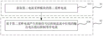
in another possible embodiment, as shown in fig. 10, step S1 includes:
s13, acquiring a second sampling current of the second current sampling module;
step S2 includes:
and S26, generating a control signal based on the second sampling current to control the output voltage value of the direct current neutral terminal so as to inhibit the zero sequence current.
The zero sequence current suppression process of the power conversion device of the embodiment is as follows:
the zero sequence current value of the machine side converter is obtained through the first current sampling module 42, and when the zero sequence current of the machine side is smaller than a threshold value, the relative potentials of the direct current neutral terminal 34, the first output terminal 33 and the second output terminal 35 of the three-level converter 22 are maintained. When the output voltage value of the dc neutral terminal 34 is reduced, the zero sequence current of the machine-side converter becomes larger.
When the zero sequence current of the machine side is greater than the threshold value, the output voltage value of the direct current neutral terminal 34 of the three-level converter 22 is adjusted, the relative potentials of the first output terminal 33 and the second output terminal 35 are kept unchanged, the output voltage value of the direct current neutral terminal 34 is increased, and the zero sequence current of the machine side converter is reduced due to the increase of the output voltage value of the direct current neutral terminal 34.
The zero sequence current value of the grid-side converter is obtained through the second current sampling module 43, and when the zero sequence current of the grid side is smaller than the threshold value, the relative potentials of the direct current neutral terminal 34, the first output terminal 33 and the second output terminal 35 of the three-level converter 22 are maintained. When the output voltage value of the dc neutral terminal 34 is reduced, the zero sequence current of the grid-side converter becomes larger.
When the zero sequence current of the grid side is greater than the threshold value, the output voltage value of the direct current neutral terminal 34 of the three-level converter 22 is adjusted, the relative potentials of the first output terminal 33 and the second output terminal 35 are kept unchanged, the output voltage value of the direct current neutral terminal 34 is increased, and the zero sequence current of the grid side converter is reduced due to the increase of the output voltage value of the direct current neutral terminal 34.
According to the zero sequence current suppression method, the second current sampling module is arranged between the output end of the grid-side converter and the input end of the transformer, so that effective suppression can be performed when the zero sequence current of the grid-side converter exceeds the standard.
The zero sequence current suppression method of the embodiment obtains the current of the alternating current input end, generates the control signal based on the current of the alternating current input end to control the output voltage value of the direct current neutral end to suppress the zero sequence current, does not need an additional signal sampling circuit, and simplifies the circuit design; by arranging the sampling circuit and the impedance circuit, the accuracy of zero sequence current suppression is improved, the independent or simultaneous suppression of the zero sequence currents of the machine side converter and the grid side converter is realized, the control method is simple, and the applicable scene is wide.
The zero sequence current suppression method of the embodiment realizes zero sequence current suppression by acquiring a zero sequence current signal in the power conversion device and generating a control signal based on the zero sequence current signal to control a direct current neutral end output voltage value, saves a common mode magnetic ring compared with the existing realization mode, and reduces material cost.
While specific embodiments of the invention have been described above, it will be appreciated by those skilled in the art that this is by way of example only, and that the scope of the invention is defined by the appended claims. Various changes and modifications to these embodiments may be made by those skilled in the art without departing from the spirit and scope of the invention, and these changes and modifications are within the scope of the invention.
Claims (12)
1. A three-level converter comprises a first output end, a second output end and a direct current neutral end, and is characterized by also comprising N two-level converters;
each two-level converter comprises an alternating current input end, a first direct current output end and a second direct current output end, wherein the potential value of the first direct current output end is greater than that of the second direct current output end;
n two-level converters are arranged from a first converter to an Nth converter according to the relative voltage value to the ground;
a first direct current output end of the first converter is used as the first output end;
a second direct current output end of the Nth converter is used as the second output end;
from the first converter to the Nth converter, the second DC output terminal of the two-level converter with higher relative voltage to ground in any two adjacent two-level converters is connected with the first DC output terminal of the two-level converter with lower relative voltage to ground to form a first series output terminal to an N-1 th series output terminal;
n is an odd number larger than 1, and the three-level converter further comprises a first capacitor and a second capacitor; one end of the first capacitor is connected with the (N-1)/2 th series output end, the other end of the first capacitor is connected with one end of the second capacitor, and the other end of the second capacitor is connected with the (N +1)/2 th series output end; the connection point of the first capacitor and the second capacitor is used as the direct current neutral terminal; the second direct current output end of the (N-1)/2 th converter is connected with the first direct current output end of the (N +1)/2 th converter to form an (N-1)/2 th series output end; and the second direct current output end of the (N +1)/2 th converter is connected with the first direct current output end of the (N +3)/2 th converter to form (N + l)/2 th series output.
2. The three-level converter according to claim 1, wherein N equals 3;
the three two-level converters are arranged according to the relative voltage value to the ground to form a third converter, a fourth converter and a fifth converter;
a first direct current output end of the third converter is used as the first output end;
a second direct current output end of the fifth converter is used as the second output end;
the second direct current output end of the third converter is connected with the first direct current output end of the fourth converter to form the first series output end;
the second direct current output end of the fourth converter is connected with the first direct current output end of the fifth converter to form a second series output end;
one end of the first capacitor is connected with the first series output end, the other end of the first capacitor is connected with one end of the second capacitor, and the other end of the second capacitor is connected with the second series output end;
and the connection point of the first capacitor and the second capacitor is used as the direct current neutral terminal.
3. A power conversion arrangement comprising a control module, at least one three-level converter according to any of claims 1-2 and N grid-side converters, one said two-level converter corresponding to each said grid-side converter; the alternating current input end is electrically coupled to an output end of a generator, and the first output end, the second output end, the first series output end to the (N-1) th series output end are respectively and electrically coupled to a direct current input end of the corresponding grid-side converter; the direct current neutral potential end is electrically coupled to a first neutral potential end of the generator;
the control module is used for generating a control signal based on the collected zero sequence current signal in the power conversion device so as to control the output voltage value of the direct current neutral terminal and inhibit the zero sequence current.
4. A power conversion arrangement according to claim 3, characterized in that the zero sequence current signal is a zero sequence component calculated from the current at the ac input.
5. The power conversion device according to claim 3, further comprising a first current sampling module;
the first current sampling module is electrically coupled between the first neutral potential end and the direct current neutral potential end;
the zero sequence current signal is a zero sequence component generated by calculating the sampling current of the first current sampling module.
6. The power conversion device according to claim 3, further comprising a second current sampling module;
the output end of the grid-side converter is connected with the input end of the transformer;
the second current sampling module is electrically coupled between the direct current neutral potential end and a second neutral potential end of the transformer;
the zero sequence current signal is a zero sequence component generated by calculating the second sampling current of the second current sampling module.
7. The power conversion device according to claim 3, characterized in that the power conversion device further comprises a first impedance circuit;
the first impedance circuit is electrically coupled between the first neutral potential terminal and the DC neutral potential terminal.
8. The power conversion device according to claim 6, characterized in that the power conversion device further comprises a second impedance circuit;
the second impedance circuit is electrically coupled between the DC neutral potential terminal and the second neutral potential terminal.
9. A zero-sequence current suppression method applied to the power conversion apparatus according to claim 3, the zero-sequence current suppression method comprising:
acquiring the zero sequence current signal;
and generating the control signal based on the zero sequence current signal to control the output voltage value of the direct current neutral terminal to inhibit the zero sequence current.
10. The zero sequence current suppression method according to claim 9, wherein the current at the ac input end comprises three-phase input currents of a plurality of the two-level converters;
the zero-sequence current signal is a zero-sequence component generated by calculating the three-phase input current;
the step of obtaining the zero sequence current signal comprises:
acquiring the three-phase input current;
the step of generating the control signal to control the output voltage value of the dc neutral terminal to suppress the zero sequence current based on the zero sequence current signal comprises:
adding a plurality of three-phase input currents to obtain the zero-sequence current;
judging whether the zero sequence current exceeds a threshold value;
and if so, outputting the control signal to the three-level converter to control and increase the output voltage value of the direct current neutral terminal so as to inhibit the zero sequence current.
11. The zero sequence current suppression method according to claim 9,
the power conversion device further comprises a first current sampling module;
the first current sampling module is electrically coupled between the first neutral potential end and the direct current neutral potential end;
the zero sequence current signal is a zero sequence component generated by calculating the first sampling current of the first current sampling module;
the step of obtaining the zero sequence current signal comprises:
acquiring a first sampling current of the first current sampling module;
the step of generating the control signal to control the output voltage value of the dc neutral terminal to suppress the zero sequence current based on the zero sequence current signal comprises:
and generating a control signal based on the first sampling current to control the output voltage value of the direct current neutral terminal so as to inhibit the zero sequence current.
12. The zero sequence current suppression method according to claim 9,
the power conversion device further comprises a second current sampling module;
the output end of the grid-side converter is connected with the input end of the transformer;
the second current sampling module is electrically coupled between the direct current neutral potential end and a second neutral potential end of the transformer;
the zero-sequence current signal is a zero-sequence component generated by calculating a second sampling current of the second current sampling module;
the step of obtaining the zero sequence current signal comprises:
acquiring a second sampling current of the second current sampling module;
the step of generating the control signal to control the output voltage value of the dc neutral terminal to suppress the zero sequence current based on the zero sequence current signal comprises:
and generating a control signal based on the second sampling current to control the output voltage value of the direct current neutral terminal to inhibit the zero sequence current.
Priority Applications (1)
| Application Number | Priority Date | Filing Date | Title |
|---|---|---|---|
| CN202011127858.6A CN112290811B (en) | 2020-10-19 | 2020-10-19 | Three-level converter, power conversion device and zero-sequence current suppression method |
Applications Claiming Priority (1)
| Application Number | Priority Date | Filing Date | Title |
|---|---|---|---|
| CN202011127858.6A CN112290811B (en) | 2020-10-19 | 2020-10-19 | Three-level converter, power conversion device and zero-sequence current suppression method |
Publications (2)
| Publication Number | Publication Date |
|---|---|
| CN112290811A CN112290811A (en) | 2021-01-29 |
| CN112290811B true CN112290811B (en) | 2021-11-05 |
Family
ID=74424452
Family Applications (1)
| Application Number | Title | Priority Date | Filing Date |
|---|---|---|---|
| CN202011127858.6A Active CN112290811B (en) | 2020-10-19 | 2020-10-19 | Three-level converter, power conversion device and zero-sequence current suppression method |
Country Status (1)
| Country | Link |
|---|---|
| CN (1) | CN112290811B (en) |
Citations (4)
| Publication number | Priority date | Publication date | Assignee | Title |
|---|---|---|---|---|
| CN104935182A (en) * | 2014-03-20 | 2015-09-23 | 南车株洲电力机车研究所有限公司 | Transformer used for three-level traction current transformer |
| CN205430084U (en) * | 2016-04-01 | 2016-08-03 | 山东大学 | Many three inverter's on T type of SHEPWM modulation zero sequence circulation restraint system |
| EP3244526A1 (en) * | 2016-04-29 | 2017-11-15 | Delta Electronics (Shanghai) Co., Ltd. | Hybrid topology power converter and control method thereof |
| CN110971129A (en) * | 2019-12-26 | 2020-04-07 | 深圳市禾望电气股份有限公司 | Power generation converter and wind generating set |
Family Cites Families (1)
| Publication number | Priority date | Publication date | Assignee | Title |
|---|---|---|---|---|
| US9450503B2 (en) * | 2013-08-15 | 2016-09-20 | General Electric Company | Power converter with a multi-level bridge topology and control method |
-
2020
- 2020-10-19 CN CN202011127858.6A patent/CN112290811B/en active Active
Patent Citations (4)
| Publication number | Priority date | Publication date | Assignee | Title |
|---|---|---|---|---|
| CN104935182A (en) * | 2014-03-20 | 2015-09-23 | 南车株洲电力机车研究所有限公司 | Transformer used for three-level traction current transformer |
| CN205430084U (en) * | 2016-04-01 | 2016-08-03 | 山东大学 | Many three inverter's on T type of SHEPWM modulation zero sequence circulation restraint system |
| EP3244526A1 (en) * | 2016-04-29 | 2017-11-15 | Delta Electronics (Shanghai) Co., Ltd. | Hybrid topology power converter and control method thereof |
| CN110971129A (en) * | 2019-12-26 | 2020-04-07 | 深圳市禾望电气股份有限公司 | Power generation converter and wind generating set |
Also Published As
| Publication number | Publication date |
|---|---|
| CN112290811A (en) | 2021-01-29 |
Similar Documents
| Publication | Publication Date | Title |
|---|---|---|
| JP4322250B2 (en) | Transformer-less grid-connected power conversion circuit | |
| CN110048626B (en) | Inverter alternating current closing common-mode impact current suppression method and application device thereof | |
| EP2270968B1 (en) | Power Transmission Method and Power Transmission Apparatus | |
| US9525284B2 (en) | Medium voltage DC collection system with power electronics | |
| CN106374830B (en) | High-power high step-up ratio photovoltaic DC converter device and control method | |
| US20150123402A1 (en) | Magnetic structure combining normal mode and common mode inductance | |
| US9611836B2 (en) | Wind turbine power conversion system | |
| US10972016B2 (en) | Multilevel converter circuit and method | |
| US11329544B2 (en) | Filter arrangement | |
| US20140203559A1 (en) | Connection for improved current balancing between parallel bridge circuits | |
| US20210151240A1 (en) | Inductor assembly | |
| US9379627B2 (en) | Power conversion circuit arrangements utilizing resonant alternating current linkage | |
| CN105703689A (en) | High-power brushless doubly-fed machine three-level bidirectional variable-frequency speed regulation system | |
| JP2009273355A (en) | Apparatus for transmitting electric power | |
| CN113726136B (en) | conversion device | |
| CN102496932A (en) | Parallel voltage sag compensation device | |
| CN115133567A (en) | Photovoltaic system and leakage current control method thereof | |
| CN112290811B (en) | Three-level converter, power conversion device and zero-sequence current suppression method | |
| CN218242998U (en) | Photovoltaic inverter system protection circuit and protection system | |
| CN106416031A (en) | Transient current protection device for electrical energy conversion systems connected to the power grid | |
| WO2016171575A1 (en) | Dc/dc/ac converter system | |
| CN113726137B (en) | conversion device | |
| CN210821908U (en) | High-speed railway load characteristic adjusting device based on modularization multi-level | |
| CN209823436U (en) | Energy taking circuit and flexible direct current transmission system | |
| CN112865579B (en) | Inverter circuit for inhibiting common mode leakage current and inverter |
Legal Events
| Date | Code | Title | Description |
|---|---|---|---|
| PB01 | Publication | ||
| PB01 | Publication | ||
| SE01 | Entry into force of request for substantive examination | ||
| SE01 | Entry into force of request for substantive examination | ||
| GR01 | Patent grant | ||
| GR01 | Patent grant |